Transcription
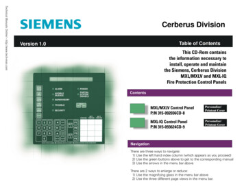
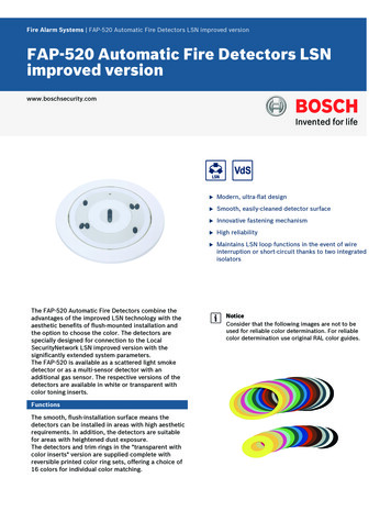
Fire Alarm Systems FAP‑520 Automatic Fire Detectors LSN improved versionFAP‑520 Automatic Fire Detectors LSNimproved versionwww.boschsecurity.comThe FAP‑520 Automatic Fire Detectors combine theadvantages of the improved LSN technology with theaesthetic benefits of flush-mounted installation andthe option to choose the color. The detectors arespecially designed for connection to the LocalSecurityNetwork LSN improved version with thesignificantly extended system parameters.The FAP‑520 is available as a scattered light smokedetector or as a multi-sensor detector with anadditional gas sensor. The respective versions of thedetectors are available in white or transparent withcolor toning inserts.FunctionsThe smooth, flush-installation surface means thedetectors can be installed in areas with high aestheticrequirements. In addition, the detectors are suitablefor areas with heightened dust exposure.The detectors and trim rings in the "transparent withcolor inserts" version are supplied complete withreversible printed color ring sets, offering a choice of16 colors for individual color matching.uModern, ultra-flat designuSmooth, easily-cleaned detector surfaceuInnovative fastening mechanismuHigh reliabilityuMaintains LSN loop functions in the event of wireinterruption or short-circuit thanks to two integratedisolatorsNoticeConsider that the following images are not to beused for reliable color determination. For reliablecolor determination use original RAL color guides.
2 FAP‑520 Automatic Fire Detectors LSN improved 200180033210168011900310019011Sensor technology and signal processingAll detectors in the FAP‑520 Series are equipped withtwo optical sensors and a pollution sensor. TheFAP‑OC‑520 multisensor detector contains a gassensor as an additional detection channel.The individual sensors can be programmed with RPSor WinPara software via the LSN network.All sensor signals are constantly analyzed by theinternal signal evaluation electronics and are linkedwith each other through algorithms.By linking the optical sensors and the gas sensor, theOC detector can also be used in places where thework carried out gives rise to small amounts of smoke,steam or dust.The alarm will only be triggered automatically if thesignal combination corresponds with the characteristicdiagram of the installation location that was selectedduring configuring. Consequently, a very high reliabilityagainst false alarms is obtained.When 50% of the alarm threshold is reached, a prealarm is signaled (displayed in the event database ofthe fire panel).Optical sensor (smoke sensor)The optical sensor (1) operates according to thescattered light method.The LEDs (3) transmit light at a defined angle into thescattered light area (7).237In case of fire, the light is scattered by the smokeparticles and strikes the photo diodes (2), whichtransform the quantity of light into a proportionalelectrical signal.Interference effects from daylight and commerciallighting sources are filtered out with an opticaldaylight filter and by the use of electronic filtering andphase-locked rectification (ambient light stability:glare test DIN EN 54‑7).The various light-emitting and photo diodes of thesensor are individually controlled by the detectorelectronics. Consequently, signal combinations areproduced that are independent of each other andideally suitable for the detection of smoke, whichmakes it possible to differentiate between smoke andinterference agents (insects, objects). In addition, thetime characteristics and the correlation of the opticalsensor signals for the fire or interference detection areevaluated.Moreover, plausibility checking of the various signalsmakes it possible to detect errors in the analysiselectronics and the LEDs.Chemical sensor (CO gas sensor)The gas sensor (4) detects mainly the carbonmonoxide (CO) that is produced by a fire, but it alsodetects hydrogen (H) and nitrogen monoxide (NO).The basic measuring principle is CO oxidation on anelectrode and the measurable current that arises fromthis. The sensor signal value is proportional to theconcentration of gas.The gas sensor delivers additional information toeffectively suppress deceptive values.The CO sensor is monitored by measuring the internalcapacity. If the capacity lies outside the permittedrange, an error message is output on the fire panel. Inthis case, the detector continues to operate purely asa scattered light smoke detector.Depending on the service life of the gas sensor, theFAP‑OC 520 Fire Detector switches off the C sensorsafter five years of operation. The detector will continueto function as an O detector. The detector should thenbe exchanged immediately in order to be able to keepusing the higher reliability of detection of theOC detector.Pollution sensorThe contamination level on the detector surface iscontinually measured by the pollution sensor (6); theresult is evaluated and indicated in three stages on thefire panel.
3 FAP‑520 Automatic Fire Detectors LSN improved versionImproved LSN featuresThe detectors offer all the features of the improvedLSN technology: Flexible network structures, including "T-tapping"without additional elements Up to 254 LSN improved elements per loop or stubline Automatic or manual detector addressing selectablevia rotary switch, in each case with or without autodetection Power supply for connected elements via LSN bus Unscreened fire detection cable can be used Cable length up to 3000 m (with LSN 1500 A) Downwards compatibility to existing LSN systemsand control panels.In addition, the detectors offer all the establishedbenefits of LSN technology. The following data can beread out for each configured detector: Serial numberContamination level of the optical section,Operating hoursCurrent analog values.In the event of an alarm, individual detectoridentification is transmitted to the fire panel.The sensor is self-monitoring. The following errors areindicated on the fire panel: Failure of the evaluation electronics or one of theLEDs on the optical sensor Heavy contamination (instead of false alarm) Failure of the CO sensor (if present).Further performance characteristicsVarious operating states are indicated on the detectorby means of a clearly visible two-color LED. In theevent of an alarm, the LED flashes red.The innovative detector locking, which operates on theballpoint-pen principle, provides fast and simpleinsertion and replacement of the detector. Werecommend the specially developed FAA‑500‑RTLexchanger device, especially in the case of highinstallation heights.To allow convenient detector testing, the FAA‑500‑TTLtest adapter with magnet and additional serviceaccessories is available.The control of an external detector alarm display ispossible.Preservation of the LSN loop function is guaranteed inthe event of wire interruption or short circuit by meansof integrated isolators.RegionRegulatory compliance/quality marksGermanyVdSG 205125 FAP-O 520/520-P G205125VdSG 205119 FAP-OC 520/520P G205119CEFAP-520/FAA-500-RCPD0786-CPD-20201 FAP-O 520 / 520-PCPD0786-CPD-20202 FAP-OC 520 / 520-PCNBOP2565/2007 FAP-O 520, FAP-O 520-PCNBOP2566/2007 FAP-OC 520, FAP-OC 520PTMTTMT-20/2006-2011 FAP-O 520, FAP-O520-PTMTTMT-21/2006-2011 FAP-OC 520, FAPOC 520-PMOEUA1.016.0002820-10 FAP-O520 -PFAA-500 tion notes Can be connected to the fire panels FPA‑5000 andFPA‑1200 with the improved LSN system parameters in "Classic Mode" can be connected to the LSN firepanels BZ 500 LSN, UEZ 2000 LSN, UGM 2020 and toother panels or their receiver modules with identicalconnection conditions, although with the previousLSN system parameters The detectors and detector bases can be usedtogether with the „Rotaris“ lamp by Philips. The detectors must be installed exclusively in theFAA‑500 LSN Bases provided. In addition, thedetector base must be installed in an FAA‑500‑BBCeiling Mount Back Box or in an FAA‑500‑SB SurfaceMount Back Box.NoticeFor flush ceiling mounting with FAA‑500‑BB:The false ceiling may have a maximum thickness of32 mm. Above the false ceiling, a free height of atleast 110 mm is required. The detectors are not intended for outdoor use. A hemispherical space with a radius of 50 cm mustremain free below the detectors.23Certifications and approvalsComplies with EN54-7:2000/A1:2002/A2:2006 EN54-17:2005150 cmContamination of the detector surface leads to activeadaptation of the threshold (drift compensation) andto a fault indication in the case of heavycontamination.1Detector2Ceiling3Hemispherical space below the detector
4 FAP‑520 Automatic Fire Detectors LSN improved version Care must be taken to ensure that neither people,large animals, plants, swinging doors nor any objectsintrude into this area and that no parts of thedetector surface become covered. The detectors may only be installed in a positionwhich is out of arm's reach. We therefore recommenda minimum installation height of 2.70 m. The detectors may not be installed in rooms in whichdata is transmitted by means of high-intensityinfrared light (e g. in rooms with IR systems forinterpreters). The detectors must be mounted so that they are notexposed to any direct sunlight. A minimum distance of 50 cm from lamps must bemaintained. The detectors may not be mounted in acone of light from lamps. The bases are equipped as standard with a springwhich is suitable for installation of the detector infalse ceilings. When the detector is installed inconcrete or wooden ceilings, these need to bereplaced by the stronger springs FAA‑500‑SPRINGwith red markings. Maximum permitted air speed: 20 m/s Country-specific standards and guidelines must beobserved during the planning phase.Installation/configuration notes in accordance withVdS/VDE The FAP‑OC 520, like the FAP‑O 520, is plannedaccording to the guidelines for optical detectors (seeDIN VDE 0833 Part 2 and VDS 2095). Detector front plateFAP‑O 520‑P/FAP‑OC 520‑PWeighttransparent/silver-grayWithout / with packaging FAP-OC 520(-P)180 g / 370 g FAP-O 520(-P)170 g / 360 g Trim Ring30 g / 60 gEnvironmental conditionsPermissible operatingtemperature FAP-O 520 (-P)-20 C to 65 C FAP-OC 520 (-P)-10 C to 50 CPermissible relative humidity95% (non-condensing)Permissible air speed20 m/sProtection class as perEN 60529 FAP-O 520 (-P)IP 53 FAP-OC 520 (-P)IP 33PlanningTechnical specificationsMonitoring areaMax. 120 m2 (Heed local guidelines!)ElectricalMaximum installation height16 m (Heed local guidelines!)Minimum installation heightOut of arm's reachMinimum installation heightrecommended by BOSCH: 2.70 m0.5 mOperating voltage15 V DC to 33 V DCCurrent consumption 3.25 mAAlarm outputPer data word by two-wire signal lineMinimum distance to lampsIndicator outputOpen collector connects 0 V over1.5 kΩ through, max. 15 mAFor flush ceiling mountingwith FAA-500-BBMechanicsDimensions DetectorØ 113 x 55 mm Detector with Tim RingØ 150 x 55 mm Detector with TrimRing, Base and CeilingMount Back BoxØ 150 x 110 mmHousing material Thickness of the falseceilingMax. 32 mm Required bored holeØ 130 mm (-1 mm to 5 mm) Installation depth110 mmNote: Above the false ceiling, a freeheight of at least 110 mm is required.Further characteristicsPolycarbonateColor Detector housingSignal white, RAL 9003 Detector front plateFAP‑O 520/FAP‑OC 520signal white mattDetection principle FAP-O 520(-P)Scattered light measurement FAP-OC 520(-P)Combination of scattered lightmeasurement and combustion gasmeasurementResponse sensitivity FAP-O 520(-P) 0.18 dB/m (EN 54-7)
5 FAP‑520 Automatic Fire Detectors LSN improved version FAP-OC 520(-P)Individual displayOptical section: 0.36 dB/m(EN 54‑7)Gas sensor section: in ppm rangeTwo-color LED,red (alarm), green (test mode)Ordering informationFAP-O 520 Smoke detector optical, whiteanalog addressable detector with optical sensor, ultraflat designOrder number FAP-O 520FAP-O 520-P Smoke detector, optical, color insertsanalog addressable detector with optical sensor andultra-flat design, transparent with color insertsOrder number FAP-O 520-PFAP-OC 520 Detector, optical/chemical, whiteanalog addressable detector with optical and chemicalsensor, ultra-flat designOrder number FAP-OC 520FAP-OC 520-P Detector optical/chemical, color insertsanalog addressable detector with optical and chemicalsensor, ultra-flat design, transparent with color insertsOrder number FAP-OC 520-PAccessoriesFAA-500-TR-W Trim ring, whitefor 500 and 520 Series Fire DetectorsOrder number FAA-500-TR-WFAA-500-TR-P Trim ring, coloredfor 500 and 520 Series Fire DetectorsOrder number FAA-500-TR-PFAA-500 Detector basefor installation of the FAP‑520 Fire DetectorOrder number FAA-500FAA-500-R Base with relayOnly used in conjunction with the 5000 Series ModularFire Panel.Order number FAA-500-RFAA-500-GB FAA-500-GB GB-base LSNrequired for installation from FAP-520 base in GreatBritainOrder number FAA-500-GBFAA-500-R-GB FAA-500-R-GB GB-base LSN with relayusable only in conjunction with the 5000 SeriesModular Fire PanelOrder number FAA-500-R-GBFAA-500-BB Back box ceiling-mountfor ceiling flush installation in false ceilings whenmounting 500 and 520 Series Bases and Fire DetectorsOrder number FAA-500-BBFAA-500-CB Housing for concrete ceilingsfor installing 500 and 520 Series Fire Detectors inconcrete ceilings. In addition, you need to order aFAA‑500‑BB Ceiling Mount Back Box, which containsthe base and the detector.Order number FAA-500-CBFAA-500-SB-H Back box for damp rooms, surface-mountfor special applications where it is not possible toflush-mount the 500 and 520 Series Fire Detectors in aceilingOrder number FAA-500-SB-HFAA-500-SPRING Spring for wooden/concrete ceilings(DU 10 units)Order number FAA-500-SPRING
6 FAP‑520 Automatic Fire Detectors LSN improved versionFAP‑520 Automatic Fire Detectors LSN improved versionFAP-O 520 Smokedetector optical, whiteFAP-O 520-P Smokedetector, optical, colorinsertsFAP-OC 520 Detector,optical/chemical, whiteFAP-OC 520-P Detectoroptical/chemical, colorinsertsDetector Operating voltage15 V DC . . . 33 V DC15 V DC . . . 33 V DC15 V DC . . . 33 V DC15 V DC . . . 33 V DCCurrent consumption 3.26 mA 3.26 mA 3.26 mA 3.26 mAProtection categoryIP 53IP 53IP 33IP 33Permissible operatingtemperature-20 C . . . 65 C-20 C . . . 65 C-10 C . . . 50 C-10 C . . . 50 CMonitoring areamax. 120 m²max. 120 m²max. 120 m²max. 120 m²Maximum installation height16 m16 m16 m16 mColorwhitetransparent with colorinsertswhitetransparent with colorinsertsRepresented by:Europe, Middle East, Africa:Bosch Security Systems B.V.P.O. Box 800025600 JB Eindhoven, The NetherlandsPhone: 31 40 2577 y.comGermany:Bosch Sicherheitssysteme GmbHRobert-Bosch-Ring 585630 GrasbrunnGermanywww.boschsecurity.com Bosch Security Systems 2017 Data subject to change without notice1254569611 en, V12, 14. Aug 2017North America:Bosch Security Systems, Inc.130 Perinton ParkwayFairport, New York, 14450, USAPhone: 1 800 289 0096Fax: 1 585 223 a-Pacific:Robert Bosch (SEA) Pte Ltd, Security Systems11 Bishan Street 21Singapore 573943Phone: 65 6571 2808Fax: 65 6571 .asia
significantly extended system parameters. The FAP‑520 is available as a scattered light smoke detector or as a multi-sensor detector with an additional gas sensor. The respective versions of the detectors are available in white or transparent with color toning inserts. 1001 10