Transcription
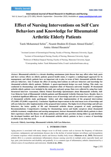
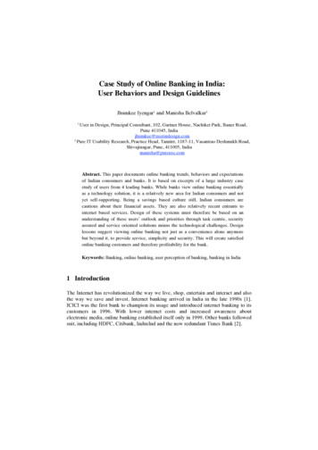
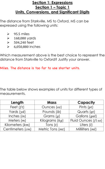
The Behaviors of H-section Steel Beam in FireYULI DONG and XIAODONG LISchool of Civil EngineeringQingdao Technological UniversityQingdao 266033, P.R. ChinaABSTRACTIn this paper, the behaviors of 14 H-section steel beams in fire are investigated. The testis carried out by use of the self-made fire-test furnace. The lengths of beams are4200 mm and 3600 mm. The temperature field and deflection of beams in fire aremeasured. The effect of connection, boundary condition and axial restraint on thebehaviors of steel beams is also studied. The test indicates that local buckling and lateraltorsional buckling of H-section steel beams occur in fire. The behaviors of H-section steelbeams in fire are influenced by connection and axial restraint. When the beams undergo alarge deflection, compression force then quickly changes into tension force, whichsupports the beam and reduces further deflection, and the catenary action takes place. Thetest results in this paper may be used to guide the design of this type of steel beams infire.KEYWORDS: fire, H-section, steel beam, temperature field, deflection, experimentaltestsINTRODUCTIONThe behaviors of steel beams have been analyzed numerical [1-3]. Some test results areavailable in the literature [4] and will be considered in the comparison. To avoid possiblebias in the conclusions, it is desirable to obtain test results as wide as possible, in relationto the total number of tests as well as the number of different independent sources. As itwas not possible to find all the necessary experimental cases, it was decided to performthe new series of experimental full-scale tests.EXPERIMENTAL EQUIPMENTS AND INSTRUMENTATIONThe test program was intended primarily to assess the benefits of structural continuity infire, on the basis of results of a series of fire tests which include typical beam-to-columnconnections and different boundary conditions. The beam specimen was subjected to aconstant vertical load, and the furnace (Fig. 1) was programmed to follow thetemperature-time curve as in Fig. 2. Six thermocouples of K type were installed aroundthe furnace to measure the fire temperatures. Some 21 other K-type thermocouples wereinstalled on the specimen beam to record the temperature distribution (Fig. 3).The behaviors of the beams were assessed in terms of the moment and thrust resisted bythe connections and the mid-span deflection of the beam. The moments and thruststransmitted by the connections to the columns were determined by measuring thehorizontal reaction forces at the top and bottom of the columns using calibrated-pin loadcells. Displacement transducers were placed near to the ends of the beam and on thecolumn to measure rotations. Figures 4 and 5 show the locations of some basicinstruments on the test beam. The loading was applied manually at room temperature. Itwas then maintained at the same level during the fire test.FIRE SAFETY SCIENCE–PROCEEDINGS OF THE EIGHTH INTERNATIONAL SYMPOSIUM, pp. 201-209COPYRIGHT 2005 INTERNATIONAL ASSOCIATION FOR FIRE SAFETY SCIENCE201
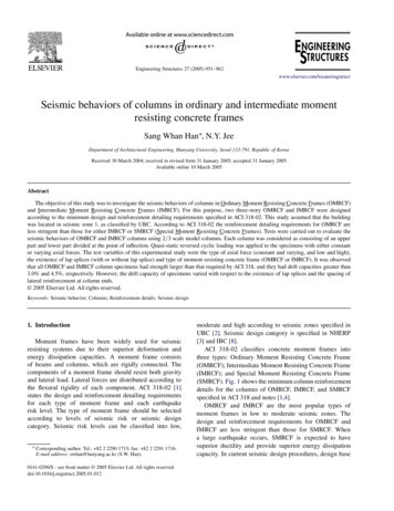
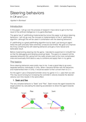
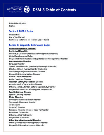
7006000Temperature( . 1. Test furnace.Fig. 2. Temperature-time curve.displacement transducerdisplacement transducerloadcellsection with thermocouplesFig. 3. Thermocouple distribution.Fig. 4. Instrumentation in the test assembly.Reaction frameReaction frameLoad cellLoad cellColumnReaction frameColumnJackSteel beamframeLoad cellLoad cellFurnaceFig. 5. Test set-up diagram.EXPERIMENTAL PROGRAMThe experiment included 14 fire tests of steel beams. In order to simulate the heat-sinkeffect of the concrete slab, the top flange is wrapped with ceramic fiber blanket. Table 1lists the principal parameters of the 14 tests. Details of steel beams can be seen in Fig. 6.The load ratio is defined as the ratio of the applied load at fire limit state to the loadcarrying capacity as a simply–supported beam at room temperature.202
Table 1. Numbering schedule and details of specimens.SpecimennumberBoundaryconditionS-1both endshinged4200one endhinged,one end4200both teconnectionSR-43600Appliedload(KN)The 18.50.4830.50.78Specification ofH-section steelH B 250 125t1 6 t2 8 r 14fy 330 N/mm2Ix 4080 cm4Iy 294 cm4A 37.87 cm2EXPERIMENTAL RESULTSTemperature DistributionFigure 7 shows typical variations against time of the temperatures of the furnaceatmosphere, during the heating and cooling phases. Due to the fire protection around thetop flange its temperature initially rose much more slowly than the rest of the section.The difference between 1 and 7 increased to almost 135 C after about 7min. As the rateof rise in fire temperature reduced, the rate of rise of temperatures in the bottom flange asa result of the lower radiation reduced. However, conduction of heat into the top flangecontinued. The temperature difference between the top flange and the rest of the sectionwas thereafter reduced to as little as 80 C when the bottom temperature exceeded 610 C.Indeed, the temperatures in the top flange continued to rise further at a low rate after thefire was switched off, and its temperatures were reduced more slowly than other parts ofthe section.203
G-1SG-1M18 boltR-1Grade 10.9 M18 boltSR-1Fig. 6. Details of steel beams.204
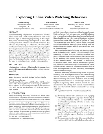
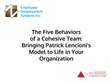
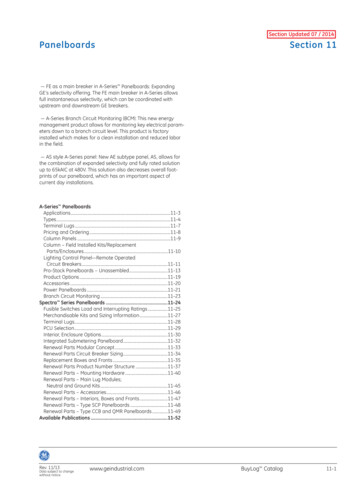
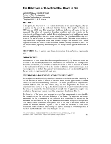
0455055Time(min)Fig. 7. Typical temperature distribution.Deflection CharacteristicsFigure 8 shows the temperature-deflection curves. Most of them were able to sustain theload without excessive deflection before limit temperature. There was the reversal ofthermal bowing temperature during the heating phases, leading to a slight reduction ofdeflection. Further rise in temperature led to a progressive run-away of beam deflectionas loss of stiffness and strength accelerated.The lateral torsional buckling was found after completion of the tests (Fig. 0204010200005 0 100 15 0 2 00 250 3 00 350 40 0 450 50 0 5 50 600 6 50 700 75 0 800050 100 150 200 250 300 350 400 450 500 550 600 650 700 750 8000Bottom flange temperature( C)0Bottom flange temperature of ( S-2SG -1SG -2G -1G -226080706050403020100050100 150 200 250 300 350 400 450 500 550 600 650 700 7500Bottom flange temperature( C)cFig. 8. Temperature-deflection curves.205
S-1SG-1R-2SR-1Fig. 9. Steel beam after fire.Effect of ConnectionsEnd-plate Connections and Fixed EndsThe top flanges of the beams were protected from direct heating. The increase oftemperature at other parts of the section leads to a thermal bowing towards the fire, whichinduces an increase in moment at the connections and moment at fixed end. Theconnections, including the bolts and the endplates, were fire-protected by ceramicblanket. Fig. 10 shows the variation with temperature of the connection moment (thefixed-end moment). It has been found that the bending moments were particular sensitiveto the actual temperature distribution at the sections near to the connection. Despite thelarge variation, the general trends are very clear. The beams have similar rates of increasein connection moment and fixed-end moment, which are irrespective of loading level andspan. As temperatures rose further, the bending moments started to decline. The reasonaffecting the point at which the bending moment started to drop is the reversal of thermalbowing temperature.6090SG-1SG-2G-1G-25070Moment at fixed end(kNm)Moment at the 4035302520151050-10-5050 100 150 200 250 300 350 400 450 500 550 600 650 700 750 8000Bottom flange temperature ( C)050 100 150 200 250 300 350 400 450 500 550 600 650 700 750 8000Bottom flange temperature ( C)abFig. 10. Temperature- moment curves.In these tests, there was a phenomenon of a sudden reduction of moment. The reason isthat the high stress due to the combinations of connection moment and axial thrust leads206
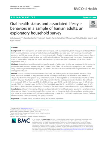
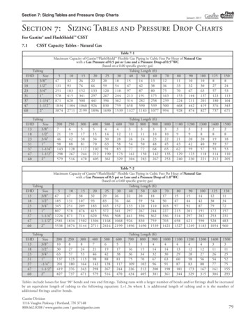
to early and progressive material softening in the vicinity of the connections. Whenplastic hinge occurs, it indicates local buckling takes place (Fig. 11). Because the fireprotection of the connection leads to a lower temperature in this zone, such plastic hingeswere not formed at the connections.G-1SR-1Fig. 11. Local flange buckling.Web-cleat ConnectionsThough normally regarded as a pinned joint, the web-cleat connection inevitably resisteda minimal amount of moment. Figure 12 shows the moment-temperature curve for webcleat connections under various conditions. As temperature increased, the connectionmoment increased subsequently, but remained fairly low. At 600 C, the connectionmoment increased suddenly. The reason is that the gap between the beam and the columnhad closed.There was no sign of local buckling in the lower flanges of these beams near to theirends. However, there were clear indications that the bolt holes in the web of the beamshad been elongated (Fig. 13). This is because of the lower value of moment capacity ofsuch connections but large bearing forces.Moment at the connection(kNm)15R-1R-2R-3R-41050-5050 100 150 200 250 300 350 400 450 500 550 600 650 700 7500Bottom flange temperature( C)Fig. 12. Temperature-connection moment curves.Fig. 13. Local photo.Effect of Axial RestraintsFigure 14 shows the axial force-temperature curves under various conditions. Axialcompression force developed when the thermal expansion in the heated steel beam wasresisted by the column. As the beam temperature increased further, the beams underwent207
a large deflection, and compression force then quickly changed into tension force, whichsupported the beam and reduced further deflection and catenary action took place.20100SR-1SR-2SR-3SR-450Axial compression force(kN)Axial compression 50-100-150-200-250-200-300-220050 100 150 200 250 300 350 400 450 500 550 600 650 700 750 800050 100 150 200 250 300 350 400 450 500 550 600 650 700 750 80000Bottom flange temperature( C)Bottom flange temperature( C)ab80R-1R-2R-3R-460Axial compression 050 100 150 200 250 300 350 400 450 500 550 600 650 700 7500Bottom flange temperature( C)cFig. 14. Temperature-axial force curves.CONCLUSIONSIn this paper, the behaviors of 14 tests of H-section steel beams in fire are investigated.All the beams are full scale with 4200 mm and 3600 mm length. In order to simulate theheat-sink effect of the concrete slab, the top flange is wrapped with ceramic fiber blanket.The test results are following:1. When H-section steel beams are in fire, lateral torsional buckling takes place.2. As the thermal bowing changes, the mid-span deflection, connection moment andmoment at fixed end change.3. The combinations of connection moment (fixed-end moment) and axial thrust lead toearly and progressive material softening in the vicinity of the end-plate connections (thefixed ends), and plastic hinge occurs.4. When the beam undergoes a large deflection, compression force then quickly changesinto tension force, which supports the beam and reduce further deflection, it indicatescatenary action takes place.208
ACKNOWLEDGMENTThis research was financially supported by the China NKBRSF project (No.2001CB409603) and the China International Joint research project of NSFC(No.50320120156). The authors deeply appreciate the support.REFERENCES[1]Bailey, C.G., Burgess, I.W., and Plank, R.J., “The Lateral-torsional Buckling ofUnrestrained Steel Beams in Fire,” Journal of Constructional Steel Research,36, pp. 101-119, (1996).[2]Liu, T.C.H., “Fire Resistance of Unprotected Steel Beams with MomentConnections,” Journal of Constructional Steel Research, 51, pp. 61-77, (1999).[3]Al-Jabri, K.S., Burgess, I.W., and Plank, R.J., “The Influence of ConnectionCharacteristics on the Behaviour of Beams in Fire,” Structural Engineering,Mechanics and Computation, 2, pp. 1087-1094, (2001).[4]Liu, T.C.H., Fahad, M.K., and Davies, J.M., “Experimental Investigation ofBehavior of Axially Restrained Steel Beams in Fire,” Journal of ConstructionalSteel Research, 58, pp. 1211-1230, (2002).209
Qingdao Technological University Qingdao 266033, P.R. China ABSTRACT In this paper, the behaviors of 14 H-section steel beams in fire are investigated. The test is carried out by use of the self-made fire-test furnace. The lengths of beams are 4200 mm and 3600 mm. The temper