Transcription
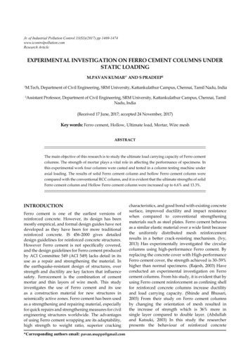
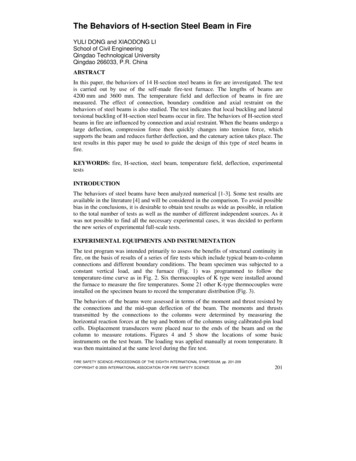
Engineering Structures 27 (2005) 951–962www.elsevier.com/locate/engstructSeismic behaviors of columns in ordinary and intermediate momentresisting concrete framesSang Whan Han , N.Y. JeeDepartment of Architectural Engineering, Hanyang University, Seoul 133-791, Republic of KoreaReceived 30 March 2004; received in revised form 31 January 2005; accepted 31 January 2005Available online 10 March 2005AbstractThe objective of this study was to investigate the seismic behaviors of columns in Ordinary Moment Resisting Concrete Frames (OMRCF)and Intermediate Moment Resisting Concrete Frames (IMRCF). For this purpose, two three-story OMRCF and IMRCF were designedaccording to the minimum design and reinforcement detailing requirements specified in ACI 318-02. This study assumed that the buildingwas located in seismic zone 1, as classified by UBC. According to ACI 318-02 the reinforcement detailing requirements for OMRCF areless stringent than those for either IMRCF or SMRCF (Special Moment Resisting Concrete Frames). Tests were carried out to evaluate theseismic behaviors of OMRCF and IMRCF columns using 2/3 scale model columns. Each column was considered as consisting of an upperpart and lower part divided at the point of inflection. Quasi-static reversed cyclic loading was applied to the specimens with either constantor varying axial forces. The test variables of this experimental study were the type of axial force (constant and varying, and low and high),the existence of lap splices (with or without lap splice) and type of moment resisting concrete frame (OMRCF or IMRCF). It was observedthat all OMRCF and IMRCF column specimens had strength larger than that required by ACI 318, and they had drift capacities greater than3.0% and 4.5%, respectively. However, the drift capacity of specimens varied with respect to the existence of lap splices and the spacing oflateral reinforcement at column ends. 2005 Elsevier Ltd. All rights reserved.Keywords: Seismic behavior; Columns; Reinforcement details; Seismic design1. IntroductionMoment frames have been widely used for seismicresisting systems due to their superior deformation andenergy dissipation capacities. A moment frame consistsof beams and columns, which are rigidly connected. Thecomponents of a moment frame should resist both gravityand lateral load. Lateral forces are distributed according tothe flexural rigidity of each component. ACI 318-02 [1]states the design and reinforcement detailing requirementsfor each type of moment frame and each earthquakerisk level. The type of moment frame should be selectedaccording to levels of seismic risk or seismic designcategory. Seismic risk levels can be classified into low, Corresponding author. Tel.: 82 2 2290 1715; fax: 82 2 2291 1716.E-mail address: swhan@hanyang.ac.kr (S.W. Han).0141-0296/ - see front matter 2005 Elsevier Ltd. All rights te and high according to seismic zones specified inUBC [2]. Seismic design category is specified in NHERP[3] and IBC [8].ACI 318-02 classifies concrete moment frames intothree types: Ordinary Moment Resisting Concrete Frame(OMRCF); Intermediate Moment Resisting Concrete Frame(IMRCF); and Special Moment Resisting Concrete Frame(SMRCF). Fig. 1 shows the minimum column reinforcementdetails for the columns of OMRCF, IMRCF, and SMRCFspecified in ACI 318 and notes [1,4].OMRCF and IMRCF are the most popular types ofmoment frames in low to moderate seismic zones. Thedesign and reinforcement requirements for OMRCF andIMRCF are less stringent than those for SMRCF. Whena large earthquake occurs, SMRCF is expected to havesuperior ductility and provide superior energy dissipationcapacity. In current seismic design procedures, design base
952S.W. Han, N.Y. Jee / Engineering Structures 27 (2005) 951–962Fig. 1. Minimum reinforcement details for columns.NotationAgf c fyMmaxMACIVACI maxθmaxgross area of columnspecified compressive strength of concretespecified yield strength of nonprestressedreinforcementmaximum moment resistance of the specimenmoment capacity calculated using ACI 318-99proceduresnominal shear strength according to ACI 31899maximum displacementmaximum drift angleshear force shall be calculated by elastic strength demanddivided by R factor ( 1). R factor accounts for ductility,overstrength, redundancy, and damping inherent in astructural system. Current design provisions assigned thehighest R factor to SMRCF, and the lowest R factor toOMRCF because of its less stringent design requirement. Itshould be noted that design base shear becomes larger withdecreasing R factor.This study focused on the behaviors of first story columnsin moment resisting frames. For this purpose, three-storyOMRCF and IMRCF buildings were designed accordingto ACI 318-02. Experimental test of columns in the firststory of those buildings was carried out to investigate theseismic behavior of the columns. This study considered thata column consisted of an upper part and lower part dividedat the point of inflection.Eight 2/3 scale column specimens (2 2 2 8)representing the lower and upper part (2) of the exterior andinterior columns (2) in the OMRCF and IMRCF (2) weremade. Lower column specimens had lap splices whereasupper column specimens had continuous longitudinalreinforcement. The most significant difference in OMRCFand IMRCF columns is the spacing of the transversereinforcement at the end of the column. Quasi-static reversedcyclic loading was applied to the specimens with either fixedor varying axial forces.The test variables in this study were type of axial force(constant and varying, and low and high), existence of lapsplices (with or without lap splice) and type of momentresisting concrete frames (OMRCF or IMRCF).2. Previous studiesHan et al. [6,7] have evaluated the seismic performanceof a three-story OMRCF. In their studies maximum lateralforce was measured during the test and compared with thedesign base shear force specified in current codes. Moreover,this study carried out seismic performance evaluation of thethree-story OMRCF using a capacity spectrum method.Lee and Woo [9] investigated the seismic performanceof low-rise reinforced concrete (RC) frames with nonseismic detailing. They considered a bare frame and amasonry infilled frame. An experiment was conducted
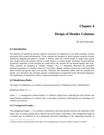
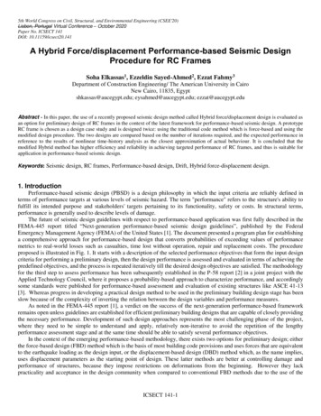
S.W. Han, N.Y. Jee / Engineering Structures 27 (2005) 951–962using 1/5 scaled specimens having two bays and threestories. They found that RC moment frames had a certainseismic resistance even though they were designed withoutconsidering seismic loads. Furthermore, masonry infill wasbeneficial to the seismic performance of the frame.Aycardi et al. [10] investigated the behavior of gravityload-designed reinforced concrete column members undersimulated seismic loading. They tested four columnspecimens governed by flexure under reversed cyclic loadingat increasing drift amplitudes. It was observed that allcolumn specimens were capable of sustaining at least twocycles of loading at a 4% drift angle.Lynn et al. [11] tested eight reinforced concrete columnspecimens having typical details of those built before themid-1970s. This study observed that column specimens thatwere governed by shear experienced gravity load failuresoon after loss of lateral force resistance. When flexurewas dominant in specimens, gravity load capacity wasmaintained to large displacement.953(a) Plan view.3. Experimental program3.1. Design of building framesTypical three-story office buildings were designed.Seismic resistance for these buildings was provided byOMRCF and IMRCF. The dimension and design loads wereadopted from Han [6]. Fig. 2 shows the dimensions of thebuilding.Specified compressive strength ( f c ) of concrete wasassumed to be 23.5 MPa. Longitudinal reinforcement andreinforcement for hoop and stirrup were assumed to have ayield strength ( f y ) of 392.3 MPa. Design loads for a typicaloffice building were used (5.2 kPa for dead load and 2.4 kPafor live load). The section of all columns and beams in themodel frames were assumed to be 330 mm 330 mm and250 mm 500 mm, respectively.The buildings were assumed to be located in seismiczone 1 as classified in UBC [2]. Member forces wereobtained using SAP 2000 (2000). Gravity loads governed themember design. Since the seismic load was small, OMRCFand IMRCF had the same member sizes as well as thesame amount of reinforcement except for the transversereinforcement in columns and beams (see Fig. 3). Thisdesign was desirable for this study since this study attemptedto investigate the effect of different reinforcement detailsof OMRCF and IMRCF columns on seismic behaviors ofthose columns without interference of other factors such asamount of longitudinal reinforcement and different membersizes.3.2. Column specimensAs shown in Fig. 2, only the columns in the first storywere evaluated since these columns should resist the largestaxial and lateral forces during an earthquake. The exterior(b) Elevation.Fig. 2. Building layouts.columns in the first story of the two model frames weredesigned for an axial force of 644.3 kN and a bendingmoment of 37 kN m, and the interior columns were designedfor an axial load of 1234.7 kN and a bending moment of47.1 kN m. It is noted that those design forces contain loadfactors.All columns had a section of 330 mm 330 mmand contained four longitudinal reinforcements (D19(19.1 mm diameter), f y 392.3 MPa). Columnlongitudinal reinforcement ratio (ρ) was 1.01%, whichslightly exceeded a minimum longitudinal reinforcing steelof 1.0% (Section 10.9.1 in ACI 318-02).Maximum shear force in the first story columns inducedby factored gravity loads was 31.4 kN. According to theformula in Section 11.3.1.2 of the ACI 318-02, the concreteshear strength of the first story columns (Vc ) was calculatedas 73.5 kN. Minimum tie reinforcement (D10 with adiameter of 9.53 mm) with spacing of 300 mm was placedthroughout the column in the OMRCF (Section 7.10.5.2in ACI 318-02) and the first tie reinforcement was placed150 mm from the slab or footing surface according
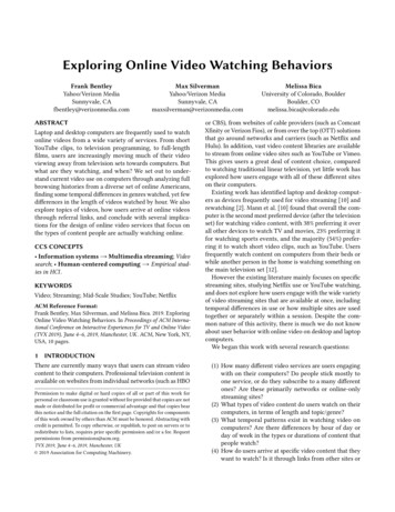
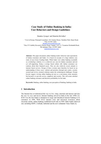
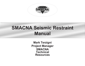
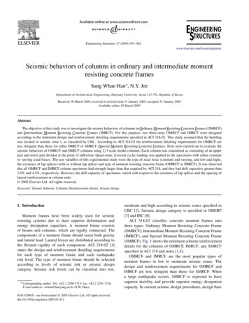
954S.W. Han, N.Y. Jee / Engineering Structures 27 (2005) 951–962Fig. 3. Column specimens.to the requirement of the first tie location specified inSection 7.10.5.4 in ACI 318-02.Fig. 3 shows that the first tie was placed 100 mm from theslab in 2/3 scale specimens. The longitudinal reinforcementdetails in the IMRCF columns and the OMRCF columnswere exactly the same. Tie spacing in the plastic hingingregion of the IMRCF columns, however, was half of the tiespacing in the OMRCF columns. The yield strength of D10was 392.3 MPa. A lap splice length of 525 mm was requiredfor tension according to Section 12.15 in ACI 318-02. Lapsplices in a column were placed just above the slabs (seeFigs. 1 and 3).It is worthwhile to note that as shown in Fig. 1 the upperpart of columns has continuous longitudinal bars whereasthe lower part of columns has lap splices. Thus this studymade specimens representing the upper part and lower partof columns (see Fig. 2). It was assumed that the inflectionpoint was located at the mid-height of the column duringearthquakes.Fig. 3 shows the reinforcement details and dimensionsof the 2/3 scale column test specimens. Table 1 describesthe characteristics of the specimens. All reinforcementswere scaled by 2/3 for test specimens. A total of eightspecimens were made (upper and lower part (2) of interiorand exterior columns in OMRCF and IMRCF (2)). Lapsplice length (350 mm) was also simply scaled by 2/3 ofthe original length (525 mm). No attempt was made to recalculate lap splice length for scaled reinforcement. RebarD13 (12.7 mm diameter) and D6 (6.35 mm diameter) wereused for longitudinal and transverse tie reinforcement torepresent 2/3 of D19 and D10 in the columns of modelframes.The dimension of column base is shown in Fig. 3.The longitudinal reinforcement of column specimens wasanchored to the column base satisfying development lengthrequired by ACI 318-02 (chapter 12). In order to fix thespecimen to the strong floor, four high strength bolts havinga diameter of 70 mm were installed (see Fig. 4(a)). All boltsare fully tightened to provide specimens with fixed baseconditions. In column base, sufficient closed type stirrupsusing reinforcement of D13 (13 mm diameter) were placedto resist the forces transferred from the specimen. No crackswere detected in the column base after test (see Fig. 4(a)).3.3. Material testsBased on concrete trial mixes from various recipes forattaining the 28-day target strength ( f c ) of 23.5 MPa, adesign mix was determined. The maximum size of aggregatefor 2/3 scale model specimens was 25 mm. Cylinder testswere performed. Each concrete cylinder was 200 mm inheight and 100 mm in diameter. Cylinder test results aregiven in Table 2.Longitudinal and transverse reinforcement in the columnspecimens (2/3 scale) were D13 (13 mm diameter) and D6(6 mm diameter), respectively. The results of material testsare given in Table 3.3.4. Loading and measurementsAll eight-column specimens were laterally loaded at thelevel of 1000 mm above the base (mid-height of a column)(see Fig. 4). It was assumed that the inflection point of acolumn is located at mid-height of the column.
S.W. Han, N.Y. Jee / Engineering Structures 27 (2005) 951–962955Fig. 4. Test setting.Table 1Characteristics of the column specimensLocationInteriorcolumnOMRCF (IMRCF)ExteriorcolumnO I L(1) (2) (3)Specimen nameLower partOIL (IIL)Upper partOIN (IIN)Lower partOEL (IEL)Upper partOEN (IEN)Loading planConstantaxial load(P 0.28)Varyingaxial load(P 1.83V 17.1)Lap splice (1): OMRCF (O), IMRCF (I) : having lap splices(2): Interior (I), Exterior (E) : not having lap splices(3): with lap splice (L), without lap splice (N)Quasi-static reversed cyclic loading (displacement controlled) was applied. Two cycles were applied for each loading amplitude. The loading history is shown in Fig. 5. Sincefluctuation of axial loads i
MACI moment capacity calculated using ACI 318-99 procedures VACI nominal shear strength according to ACI 318-99 max maximum displacement θmax maximum drift angle shear force shall be calculated by elastic strength demand divided by R factor ( 1). R factor accounts for ductility, overstrength, redundancy, and damping inherent in a structural system. Current design provisions assigned the .