Transcription
/ Marley Aquatower Cooling Tower / User Manual 01-1248E
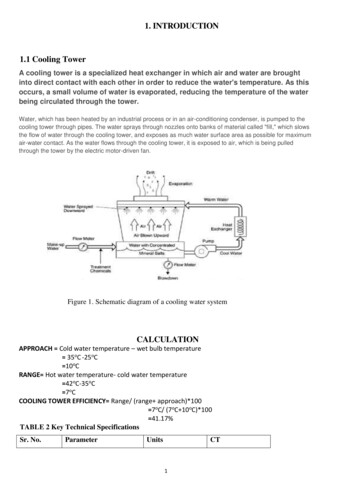
ContentsThis Manual contains vital information for the proper installation andoperation of your cooling tower. Carefully read the manual beforeinstallation or operation of the tower and follow all instructions.Save this manual for future reference.Tower Installation.3Piping to Tower.4Mechanical Equipment Installation.5Motor Electrical Connections.8Starting and Operating Instructions.9Fan Cycling Limits.11Maintenance Instructions.12Blowdown.14Seasonal Shutdown Instructions.15Troubleshooting.16Wiring Diagrams. 17Parts List.20The following defined terms are used throughout this manual to bring attentionto the presence of hazards of various risk levels, or to important informationconcerning the life of the product.WarningIndicates presence of a hazard which can cause severe personalinjury, death or substantial property damage if ignored.CautionIndicates presence of a hazard which will or can cause personalinjury or property damage if ignored.Note2Indicates special instructions on installation, operation or maintenance which are important but not related to personal injuryhazards.
InstallationReceiving InspectionThe motor and miscellaneous parts ship with the tower. Check motor nameplateto be sure that power supply and motor have the same characteristics. Inspectthe entire shipment for any damage that may have occurred in transit.Tower LocationWarningThe cooling tower must be located at such distance and direction toavoid the possibility of contaminated tower discharge air being drawninto building fresh air intake ducts. The purchaser should obtain theservices of a Licensed Professional Engineer or Registered Architectto certify that the location of the tower is in compliance with applicable air pollution, fire, and clean air codes.Locate so prevailing wind will blow into the louvered face, and direct fandischarge away from building surfaces. Locate so there is free air flow to andfrom the tower. Allow clearance on all sides for maintenance.Indoor InstallationUse a duct from the tower air discharge to the outside. You may also want toinstall an inlet air duct. Do not allow the total pressure loss through ducts toexceed 0.10 inches H2O. To minimize pressure losses: Use 20% oversize ducts. Avoid sharp turns or abrupt changes in size. Keep duct length to a minimum. Screened or louvered openings should have a net free area at least 20%greater than the tower discharge opening area.Attach ducts to the tower using flexible connections, and support ducts independently from the tower. Provide access openings for servicing the mechanicalequipment if air discharge ducts are installed. If the duct discharges into theprevailing wind, you may need to install a windbreak or an elbow to serve asa deflector. Ducts installed on towers with year-round usage should be watertight and insulated to prevent condensation. 3
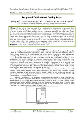
InstallationTower InstallationInstall tower in a level position on a stable foundation. Anchor tower to thefoundation through holes at base of tower, using four 3 8” diameter bolts (notsupplied). Remove strapping and brackets from the louver face on models494—496 and reinstall the bolts to the cold water basin. Install the overflow(fiberglass models only) as shown in Figure 1.INSTALL DRAIN FITTINGWITH GASKET ON TOPFigure 1Piping to Tower (Summer–Only Operation)1. Use large enough piping to minimize friction loss.2. Connect float valve to makeup water supply. Install the threaded valvestem and float located in the loose parts package.3. Install a valved blowdown line at some point in the system, preferably inthe hot water line near the top of the tower, so that water will flow throughthe line whenever the pump is operating. (Blowdown is the continuousremoval of a small amount of water during operation to retard scale vity Linefrom OutletMake-UpLineIndoorStorageTankFigure 24Overflow andDrain to SewerPumpHeatLoad
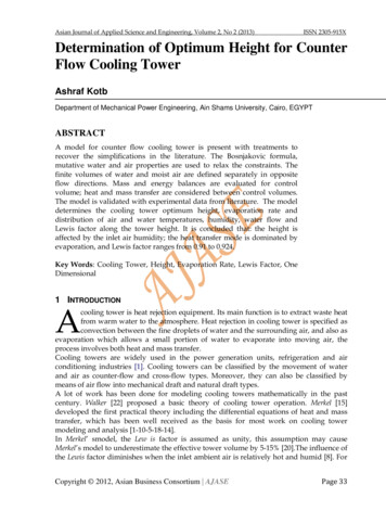
InstallationPiping to Tower (Year–Round Operation)1. If your tower must operate during freezing weather, it is recommendedthat the tower be installed for gravity flow operation. See Figure 2.2. Provide an indoor open type storage tank with a capacity that will containall water that will drain into the tank from the system during shutdown.3. Connect tower outlet to storage tank. Bottom outlet option should beused for gravity flow.4. Install makeup water, bleed-off, overflow and drain lines on tank.5. Insulate and heat water lines exposed to freezing temperatures.Mechanical Equipment InstallationAquatowers with factory-installed controls ship with the motor, sheave,belt, and belt guard factory-installed. Remove shipping stiffener plateand hardware at the adjustable end of the motor support plate andproceed to Motor Electrical Connections.NoteMotor, Sheave, and V-Belt Installation1. Check the motor nameplate to be sure its voltage, phase and frequencyratings are the same as the power supply. Belt Guard for SteelAquatower ShownMotor Frame Fastener Size56–143T–145T5182T thru 215T3 16" 8"Figure 31/4" TAP SCREWSUPPORT BRACKET(WITH ADJUSTMENT SLOTS)5
Installation2. Make sure the fan is tightly secured to the bearing housing shaft and that itrotates freely. Make sure the bearing housing is secured to its support.3. Attach motor to motor base with four bolts, flat washers, lock washersand nuts provided, see Figure 3. You may want to loosen the adjustingbolts and raise the motor base so you can reach under the motor baseto tighten the motor hold-down bolts.MOTOR SHEAVEPLUMB LINESHEAVES MUST BE PARALLEL TOEACH OTHER AND IN THE SAMEPLANE OF OPERATIONFAN SHEAVEFigure 44. Apply a rust preventive coating to the motor shaft to prevent shaft corrosion and to ease sheave installation and removal.5. Install motor sheave and align it with fan sheave. Motor support bracketsare slotted to assist in alignment. See Figure 3. A plumb line will be helpfulin aligning sheaves. See Figure 4.6. Remove the fan guard and fan cylinder splice plate (steel tower only) atthe top of the fan cylinder. Install the belt over the fan by passing the beltover the fan and rotating the fan blades past the belt. Install the belt ontothe sheaves.6
Installation7.Use the adjusting bolts on the motor support to adjust belt tension. Acorrectly tensioned belt does not slip when the fan is running—and the“tight” side is straight between sheaves. The “slack” side will have a slightbow. If possible, use a commercially available tension measuring device.Avoid over-tensioning. Too much tension reduces bearing and belt life.Check the tension on new belts after 8 to 12 hours of operation.8. Install the belt guard as shown in Figure 3 for a steel tower or Figure 5for a fiberglass tower.9. Install fan cylinder splice plate (steel tower) and fan guard.10. Check bearing housing oil cup level. Fill to the proper level with SAE 30(ISO 100) weight oil.Belt Guard for FiberglassAquatower Shown3/8" x 1 1/2" BOLT3/8" WASHERSUSE 3/8" WASHERS TOSHIM AS REQUIRED3/8" NEOPRENE WELL-NUTFigure 57
InstallationMotor Electrical ConnectionsIf Aquatower is equipped with Marley Control System, refer to ControlSystem Manual for wiring instructions.NoteConnect motor to power supply in accordance with the National ElectricCode and local requirements. Failure to wire the motor correctly will void itswarranty. Overload protection for motors must be part of the control system.Figure 6 shows one possible control scheme. Other various wiring diagramsappear on pages 19 through 22.2-WIRE CONTROL (IF USED)STOPSTARTL1OLMML2L3MMMNOTE: L3 IS USED ON 3-PHASE MOTOR ONLY.Figure 68MOTOR
OperationStarting and Operating InstructionsWarningAmong other sources, outbreaks of Legionnaires’ Disease havereportedly been traced to cooling towers. Maintenance and watertreatment procedures that prevent amplification and disseminationof Legionella and other airborne bacteria should be formulated andimplemented BEFORE systems are operated and continued regularlythereafter to avoid the risk of sickness or death.1. New installations should be cleaned and treated with biocides by a watertreatment expert before startup.2. Clean all debris, such as leaves and dirt from the cooling tower fill andbasin.3. Fill the circulating system with water. The cold water basin should be filledwith water until level is at the rim of the overflow.The water conditions during the initial tower operation are crucial in preventing premature corrosion of galvanized steel (white rust). For at leastthe first eight weeks of operation, pH should be controlled between 6.5and 8.0 with hardness and alkalinity levels between 100 and 300 ppm(expressed as CaCO3).NoteIf tower is equipped with a standard side-suction connection, ventany accumulated air from the top of the suction hood by removingone or both tap screws provided at that location. Replace these tapscrews when venting is complete.4. Start your pump(s). Observe system operation. Since the water systemexternal to the tower will have been filled only to the level in the cold waterbasin, some “pump-down” of the basin water level will occur before watercompletes the circuit and begins to fall from the fill. The initial pump-downmay not be enough to cause the float valve to open. However, you cancheck its operation by pressing down on the operating lever. Adjust thefloat valve during tower operation with heat load to maintain 4" waterdepth in the depressed section of the basin on Models 490—493. Maintain51 2" water depth on Models 494—496. 9
OperationNoteHot water temperatures exceeding 125 F could damage PVC fill.5. Make sure blowdown line is discharging water.6. Depth of water in hot water basin should be uniform. If the basin overflows,reduce the flow rate. Do not pump more water than design capacity.7.Continue pump operation for about 15 minutes, after which it is recommended that the water system be drained, flushed, and refilled.8. While operating the condensing water pump(s) and prior to operating thecooling tower fan, execute one of the two alternative biocidal treatmentprograms described in the following: Resume treatment with the biocide which had been used prior to shutdown. Utilize the services of the water treatment supplier. Maintain themaximum recommended biocide residual (for the specific biocide) fora sufficient period of time (residual and time will vary with the biocide)to bring the system under good biological controlor Treat the system with sodium hypochlorite to a level of 4 to 5 mg/L(ppm) free chlorine residual at a pH of 7.0 to 7.6. The chlorine residualmust be held at 4 to 5 mg/L (ppm) for six hours, measurable withstandard commercial water test kits.If the cooling tower has been in operation and then shut down for a duration of time and not drained, perform one of the two previous biocidaltreatment programs directly to the cooling water storage vessel (coolingtower sump, drain down tank, etc.) without circulating stagnant waterover the cooling tower fill or operating the cooling tower fan.After biocidal pretreatment has been successfully completed, coolingwater may be circulated over the tower fill with the fan off.When biocidal treatment has been maintained at a satisfactory level forat least six hours, the fan may be turned on and the system returned toservice. Resume the standard water treatment program, including biocidaltreatment.10
Operation9. Check fan for free rotation and check oil level in bearing housing asrequired (see maintenance instructions). Start motor and check direction of rotation. Fan must rotate clockwise when viewed from the fandischarge side. If the rotation is incorrect, change any two of the threemotor leads.Fan cycling limitsNoteConsidering the normal fan and motor sizes utilized on Aquatowers,anticipate that approximately 4 to 5 starts per hour are allowable.If your tower is equipped with a two-speed motor, you will enjoy greater opportunity for temperature control. When the water temperature becomes toocold, switching the fan to half-speed will cause the cold water temperatureto rise—stabilizing at a temperature a few degrees higher than before. Witha further reduction in water temperature, the fan may be cycled alternatelyfrom half-speed to off.NoteDo not start the motor more than four to five times per hour (eachlow speed start and each high speed start count as one start).If your tower consists of two or more cells, cycling of motors may be sharedbetween cells, increasing your steps of operation accordingly.Multicell towers equipped with two-speed motors will maximize energysavings and minimize sound levels if fans are staged so that all fans arebrought up to low speed before any fan goes to high speed.For greater insight on cold water temperature control, please read“Cooling Tower Energy and its Management”, Technical Report#H-001-A, available on our website.11
MaintenanceMaintenance InstructionsWarningAlways make certain that mechanical equipment is inoperable duringperiods of maintenance—or during any situation of possible endangerment to personnel. If your electrical system contains a disconnectswitch, lock it out until the period of exposure to injury is over.The top of the tower is not a working surface. Do not stand, sit orwalk on top of the tower. Use an appropriate ladder adjacent to thetower whenever you perform any maintenance activity on the tower’supper surfaces.This product is constructed of fiberglass or cold-formed sheet metal.Use protective clothing, gloves and shoes as appropriate for protection against edges of thin gage material.MotorLubricate the motor according to the motor manufacturer’s supplied instructions. Remove any oil, dust or scale deposits from the motor which can causeexcessive insulation temperatures.Refer to Electric Motors on Cooling Towers, Manual 92-1475, for additionalmaintenance and lubrication information.Fan Shaft Bearing HousingCheck bearing housing oil cup level. Fill to the proper level with SAE 30(ISO 100) weight oil.Belt TensionCheck belt tension every two to three weeks during peak operating season.Makeup Float ValveCheck float valve periodically for proper operation and proper water level.Basin and Suction ScreenDrain and clean cold water basin and suction screen periodically.BlowdownCheck the blowdown for continuous water discharge during operation.12
MaintenanceCooling Tower CleaningWarningAny evaporative-type cooling tower must be thoroughly cleaned ona regular basis to minimize the growth of bacteria, including Legionella Pneumophila, to avoid the risk of sickness or death. Servicepersonnel must wear proper personal protective equipment duringdecontamination. Do NOT attempt any service unless the fan motoris locked out.Operators of evaporative cooling equipment, such as water cooling towers, should follow maintenance programs which will reduce to an absoluteminimum the opportunity for bacteriological contamination. Public HealthService officials have recommended that “good housekeeping” proceduresbe followed, such as: regular inspections for concentrations of dirt, scale, andalgae; periodic flushing and cleaning; and the following of a complete watertreatment program including biocidal treatment. See Starting and OperatingInstructions on page 9.A visual inspection should take place at least once a week during the operatingseason. Inspect for bacterial growth and general operation conditions. Bacterial growth should be reported to your water treatment expert for immediateattention. At a minimum, cooling towers should be cleaned and disinfectedwith biocides twice a year. Systems with biofouling or positive cultures oflegionella may require additional cleaning.Inspect louvers, drift eliminators and basin trash screens and remove any debris or scale which may have accumulated. Replace any damaged or worn outcomponents. The louvers, drift eliminators and easily accessible fill surfacesshould be flushed by use of a moderate-pressure water nozzle, being carefulnot to cause physical damage. Use of high-pressure water may damage theeliminator and louver material. A reliable water treatment program should beinstalled and maintained. Filtration devices may be employed to reduce thesuspended solids concentrations, thus increasing the effectiveness of thewater treatment program.13
MaintenanceBlowdownA cooling tower cools water by continuously causing a portion of it to evaporate. Although the water lost by evaporation is replenished by the makeupsystem, it exits the tower as pure water – leaving behind its burden of dissolvedsolids to concentrate in the remaining water. Given no means of control, thisincreasing concentration of contaminants can reach a very high level.In order to achieve water quality which is acceptable to the cooling tower (aswell as the remainder of your circulating water system), the selected watertreatment company must work from a relatively constant level of concentrations. This stabilization of contaminant concentrations is usually accomplishedby blowdown, which is the constant discharge of a portion of the circulatingwater to waste. As a rule, acceptable levels on which to base a treatmentschedule are in the range of 2–4 concentrations. The following table gives approximate blowdown rates (percent of total water flow rate constantly wasted)to achieve those concentrations at various cooling ranges*:CoolingRange ( F)6811Blowdown s0.17%0.30%0.43%* Range is the difference between hot water temperature entering the tower andcold water temperature leaving the tower.NoteWhen water treatment chemicals are added, they should not be introduced into the circulating water system via the cold water basinof the cooling tower. Water velocities are lowest at that point, whichresults in inadequate mixing and may damage the cooling tower.Intermittent Wintertime Operation:If periods of shutdown (nights, weekends, etc.) occur during freezing weather,measures must be taken to prevent the water in the cold water basin—and allexposed pipework—from freezing. Several methods are used to combat this,including automatic basin heater systems available from Marley.CautionWarning14Unless some means of freeze prevention is incorporated into yoursystem, the tower basin and exposed pipework should be drained atthe beginning of each wintertime shutdown period.If tower basin is drained, verify that all basin heaters have been shutoff either by automatic cutoff or disconnect switch.
MaintenanceSeasonal Shutdown InstructionsWhen the system is to be shut down for an extended period of time, it isrecommended that the entire system (cooling tower, system piping, heatexchangers, etc.) be drained. Leave the basin drain open.During shutdown, clean the tower and make any necessary repairs. Applypr
/ Marley Aquatower Cooling Tower / User Manual 01-1248E. 2 Contents This Manual contains vital information for the proper installation and operation of your cooling tower. Carefully read the manual before installati