Transcription
Asian Journal of Applied Science and Engineering, Volume 2, No 2 (2013)ISSN 2305-915XDetermination of Optimum Height for CounterFlow Cooling TowerAshraf KotbDepartment of Mechanical Power Engineering, Ain Shams University, Cairo, EGYPTABSTRACTA model for counter flow cooling tower is present with treatments torecover the simplifications in the literature. The Bosnjakovic formula,mutative water and air properties are used to relax the constraints. Thefinite volumes of water and moist air are defined separately in oppositeflow directions. Mass and energy balances are evaluated for controlvolume; heat and mass transfer are considered between control volumes.The model is validated with experimental data from literature. The modeldetermines the cooling tower optimum height, evaporation rate anddistribution of air and water temperatures, humidity, water flow andLewis factor along the tower height. It is concluded that: the height isaffected by the inlet air humidity; the heat transfer mode is dominated byevaporation, and Lewis factor ranges from 0.91 to 0.924.Key Words: Cooling Tower, Height, Evaporation Rate, Lewis Factor, OneDimensional1 INTRODUCTIONAcooling tower is heat rejection equipment. Its main function is to extract waste heatfrom warm water to the atmosphere. Heat rejection in cooling tower is specified asconvection between the fine droplets of water and the surrounding air, and also asevaporation which allows a small portion of water to evaporate into moving air, theprocess involves both heat and mass transfer.Cooling towers are widely used in the power generation units, refrigeration and airconditioning industries [1]. Cooling towers can be classified by the movement of waterand air as counter-flow and cross-flow types. Moreover, they can also be classified bymeans of air flow into mechanical draft and natural draft types.A lot of work has been done for modeling cooling towers mathematically in the pastcentury. Walker [22] proposed a basic theory of cooling tower operation. Merkel [15]developed the first practical theory including the differential equations of heat and masstransfer, which has been well received as the basis for most work on cooling towermodeling and analysis [1-10-5-18-14].In Merkel‟ smodel, the Lew is factor is assumed as unity, this assumption may causeMerkel‟s model to underestimate the effective tower volume by 5-15% [20].The influence ofthe Lewis factor diminishes when the inlet ambient air is relatively hot and humid [8]. ForCopyright 2012, Asian Business Consortium AJASEPage 33
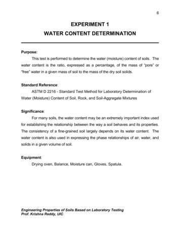
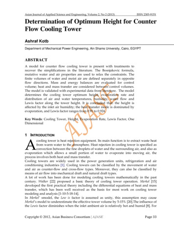
Asian Journal of Applied Science and Engineering, Volume 2, No 2 (2013)ISSN 2305-915Xincreasing Lewis factor, the heat rejection rate increases, the water outlet temperaturedecreases and the water evaporation rate decreases [12].Kroger [12] expressed the equation for the tower performance calculation using the Poppemethod, which was developed for actual unsaturated and supersaturated air beforeexiting cooling towers. Furthermore, the influence of Lewis factor on the performance ofwet cooling towers was proposed [8]. The results showed that it decreased when the inletair was relatively hot and humid. The Lewis factor is proportional to the heat transfer rate.Jameel [7] and Thirapong [21] assumed Lewis factor to be unity, constant specific heats of airand water and constant heat and mass transfer coefficients.In Merkel‟s model, the water loss of evaporation is neglected in energy balance andsaturated air at the exit. These assumptions made the results inaccurate. Zubair [24]investigated the performance characteristics through the counter-flow cooling tower, theresults showed that a majority mode of heat transfer rate is evaporation, where it was62.5% of the total heat transfer rate at the bottom and about 90% of that at the top of thetower. Since evaporation is by far the most effective factor in cooling towers, the accuracyof the predicted conditions are directly dependent on it. For this purpose, it is quitecommon to include the evaporation term in the model [16].Most of the modeling results in the literature were validated with the experimental workof Simpson [19]; Xiao [23] validated the results with those of Simpson [19] for fiveexperimental data.In this study, a mathematical model for the counter-flow cooling tower is introduced withseveral distinctive treatments to recover the most of the simplifications in the literature.First, the mutative water and air specific heats are used to relax the constraints. Second,instead of considering the Lew is factor to be unity, the formulation in Bosnjakovic [3] isapplied. Thirdly, the finite volume method is applied, where the control volumes of waterand moist air are defined separately, with opposite flow directions. Mass and energybalances are evaluated for each control volume, and the heat and mass transfer areconsidered between each pair of the water and moist-air control volumes. The steady-stateperformance of the proposed model is validated with experimental data from literature.The mathematical model solution determines the optimum height of the cooling tower,evaporation rate and distribution of air temperature, relative humidity, watertemperature, water flow rate and Lewis factor along the cooling tower height.2 MATHEMATICAL MODELThe processes of heat and mass transfer through the counter-flow cooling tower (Figure 1A) are mathematically modeled with the finite volume method. The control volume isshown in Figure1 B, C for water and moist air where the flows are in opposite directions.The modeling methodology is governed by the following assumptions [2-9-13]:1. One-dimensional flow.2. Steady-state and steady flow conditions.3. Uniform cross-sectional area.4. Heat and mass transfer are in the direction normal to the water/air flow only.5. Heat and mass transfer through the tower walls to the surroundings are negligible.6. Heat transfer from the forced/induced draft fan to air and water is neglected.7. Water loss by drift is negligible.8. The process is isobaric at standard atmospheric value.9. Potential and kinetic energies are neglected.Copyright 2012, Asian Business Consortium AJASEPage 34
Asian Journal of Applied Science and Engineering, Volume 2, No 2 (2013)ISSN 2305-915XFigure 1:A. Schematic Representation of Cooling Tower.B. Model of Cooling Tower.C. Control volume of counter flow cooling tower2.1 GOVERNING EQUATIONSThe conservation of mass flow rates for the dry air, moisture content and water throughthe control volume yields:.m a x m a m w m a (x dx) m a ( m w - d m w )(1)The conservation of mass flow rates for the control volume verifies that; the mass transferappears in decreasing the water flow rate and increasing the moisture content of the air asa result of evaporation as in Equation (2):.d m w m a dx(2)Also, the mass transfer flow rate from the water as a result of evaporation into the air is reexpressed by the definition of the mass transfer coefficient and the difference in theconcentrations of the moisture content of the air as in Equation (3) [16]:.m a dx h m ρ a a c (x sat - x) dVSince, the control volume is defined as:be in the form of Equation (4):(3)dV A dH , Then Equation (3) is simplified todx h m ρ a a c A (x sat - x).dHma(4)The conservation of energy rates for moist air and water through the control volumeyields:Copyright 2012, Asian Business Consortium AJASEPage 35
Asian Journal of Applied Science and Engineering, Volume 2, No 2 (2013).ISSN 2305-915X.m w h w m a h a m a (h a dh a ) ( m w d m w )(h w dh w )(5).Neglecting the second order derivatives(d m w dh w 0) which simplify Equation (5)to Equation (6):.m a dh a m w dh w h w d m w(6)By inserting Equation (2) into Equation (6) leads to Equation (7).m a dh a m w dh w h w m a dx(7).Equation (7) contains three terms, the first termm a dh a which represents the total rate of.m w dh wheat transferred to the moist air, while the second termrepresents the rate ofheat transfer from the water to the air and appears as sensible heating, on the other hand,.h w m a dx represents the rate of heat transfer from the water to the airthe third termand appears as a humidification.Therefore, one can say that; the rate of heat transferred from the falling water to uprisingair is transferred as a result of convection and is associated with mass transfer from waterto air as in Equation (8):.m a dh a dQ c dQ m(8)While, the rates of heats transfer by convection and evaporation are re-written as inEquation (9):.m a dh a h c a c (Tw Ta ) dV h m ρ a a c (x sat x) h v dV(9)Equation (9) is simplified to be:dh a h c a c Ah m ρa a c A h v (T T) (x sat x)wa.dHmamahcLe Using both Lewis factorh m ρ a Cpa and the cooling towerKa h m ρ a a c , then Equations (4) and (10) are re-written as follows:dx Ka A .(x sat - x)dHmaCopyright 2012, Asian Business Consortium AJASE(10)characteristics(11)Page 36
Asian Journal of Applied Science and Engineering, Volume 2, No 2 (2013)dh a Ka A . Le Cp a (Tw Ta ) (x sat x) h v dHmaISSN 2305-915X(12)Equation (7) is re-written as follows:.madTw dh a. h w dx (13)mw CwThe set of Equations (2), (11), (12) and (13) govern the processes of heat and mass transferthrough the counter-flow cooling tower.2.2 Lewis Factor and Cooling Tower CharacteristicsThe governing Equations (11) and (12) contain both Lewis factor and the cooling towercharacteristics.2.2.1 Lewis FactorLewis factor is an indication of the relative rates of heat and mass transfer in anevaporative process. Bosnjakovic [3] developed an empirical relation for the Lewis factorfor unsaturated air–water vapor systems as in Equation (14).Le 0.865 0.667 x sat 0.622 / x 0.622 1ln x sat 0.622 / x 0.622 (14)2.2.2 Cooling Tower CharacteristicsThe cooling tower characteristic, a “degree of difficulty” to cooling is represented by theMerkel Equation [4]as in Equation (14):Ka V.mw HWT dTw\CWT h a ha(15)The Merkel Equation primarily says that at any point in the tower, heat and water vaporare transferred into the air due to (approximately) the difference in the enthalpy of the airat the surface of the water and the main stream of the air. Thus, the driving force at anypoint is the vertical distance between the two operating lines. Therefore, the performancedemanded from the cooling tower is the inverse of this difference.2.3 Psychometrics and Thermo physical PropertiesThe cooling tower is an air breathing thermodynamic system, where its performance isaffected by the conditions of the ambient air. Mathematical modeling of cooling tower hasto consider the psychometrics of air, for both the dry air and its associated water vapor;the main properties such as pressures; temperatures, and enthalpies have to be welldefined also the relative humidity and moisture content.Copyright 2012, Asian Business Consortium AJASEPage 37
Asian Journal of Applied Science and Engineering, Volume 2, No 2 (2013)ISSN 2305-915XThe saturation pressure (Pa) of water vapor in the dry air at the given temperature is afunction only of temperature (K) and can be calculated from Equation (16) [6]:i 5ln(Ps ) C i T i 1 C 6 ln(T)i 0For the temperature range of 173.16 T 273.15 KCoC1C2-5.6745359x10³ 0240x10-13 4.1630159For the temperature range of 273.16 T 473.15 6-1.4452093x10⁻⁸ tive humidity (%) is the ratio of the moist air‟s absolute humidity to the absolutehumidity of saturated air at the same temperature and it is formulated as in Equation (17). 100PvPs(17)The moisture content of a given moist air sample is defined as the ratio of the mass ofwater vapor to the mass of dry air contained in the sample as in Equation (18).x 0.62198PvP - Pv(18)For lower pressures, the specific enthalpy of water vapor (J/kg) is approximately linearfunction of temperature (oC) as in Equation (19) [17]:h v 2501300 Cp v T(19)The specific heat of water vapor(J/kg.K) is a function of temperature as follows [11].Cpv 1.3605 x 10 3 2.31334 T 2.46784 x10 -10 T5 5.91332 x10 -13 T 6The specific enthalpy of moist air (J/kg) is approximately linear function of temperature(oC) as in Equation (20) [17]:h a Cp a T x h v(20)The specific heat of dry air(J/kg.K) is a function of temperature as follows [11].Cpa 1.045356 x 10³ - 3.161783 x 10⁻¹ T 7.083814x1 0-4 T 2 - 2.705209x1 0-7 T 3Also, the specific heat of water (J/kg.K) is a function of temperature as follows [11].Cw 8.15599x 10 3 2.80627x10 T 5.11283x10 -2 T 2 2.17582x10 -13 T 6Copyright 2012, Asian Business Consortium AJASEPage 38
Asian Journal of Applied Science and Engineering, Volume 2, No 2 (2013)ISSN 2305-915X2.3 Numerical FormulationThe mathematical model is numerically formulated based on the explicit scheme. Wherethe cooling tower is divided into equal numbers of control volumes (nmax), the first controlvolume (I 1) represents the lower boundary conditions at the air entrance level; the lastcontrol (I nmax) represents the upper boundary conditions at the air exit level. Therefore,Equations (2), (11), (12) and (13) are respectively numerically formulated as follows:x I x I-1 Ka A ΔH. x sat I-1 - x I-1 mah a I h a I 1 Ka A.ΔH(21) Le I-1Cp a I -1 Tw I 1 Ta I-1 x sat I 1 x I-1 h v I 1 (22)ma.Tw I Tw I 1ma h a I h a I 1 h w I 1 x I x I 1 . mw Cw I-1(23). m w m w m a x I x I 1 I I 1(24)Equations (21), (22), (23) and (24) are applied for the control volumes where (I) varies from(2) to (nmax-1).The solution procedure is based on the problem statement, where for the known designand operating conditions as illustrated in Table (1) are well known, while the solution isprepared and proceeds to determine the optimum height of the cooling tower,
Flow Cooling Tower Ashraf Kotb Department of Mechanical Power Engineering, Ain Shams University, Cairo, EGYPT ABSTRACT A model for counter flow cooling tower is present with treatments to recover the simplifications in the literature. The Bosnjakovic formula, mutative water and air properties are used to relax the constraints. The finite volumes of water and moist air are defined separately in .