Transcription
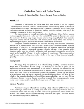
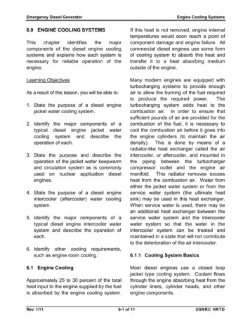
1. INTRODUCTION1.1 Cooling TowerA cooling tower is a specialized heat exchanger in which air and water are broughtinto direct contact with each other in order to reduce the water's temperature. As thisoccurs, a small volume of water is evaporated, reducing the temperature of the waterbeing circulated through the tower.Water, which has been heated by an industrial process or in an air-conditioning condenser, is pumped to thecooling tower through pipes. The water sprays through nozzles onto banks of material called "fill," which slowsthe flow of water through the cooling tower, and exposes as much water surface area as possible for maximumair-water contact. As the water flows through the cooling tower, it is exposed to air, which is being pulledthrough the tower by the electric motor-driven fan.Figure 1. Schematic diagram of a cooling water systemCALCULATIONAPPROACH Cold water temperature – wet bulb temperature 35oC -25oC 10oCRANGE Hot water temperature- cold water temperature 42oC-35oC 7oCCOOLING TOWER EFFICIENCY Range/ (range approach)*100 7oC/ (7oC 10oC)*100 41.17%TABLE 2 Key Technical SpecificationsSr. No.ParameterUnitsCT1
1Type of cooling towerInducedDraftcounter flow type2Water flowL/Hr38003Pumping PowerW404Pumping Headm1.525Fan PowerW65TABLE 3 Cooling Power PerformanceSr. No.Parameter ReferenceUnitsCT1Dry bulb temperatureC36*2Wet bulb temperatureC25*3CT inlet temperatureC42*4CT outlet temperatureC35*5RangeC7*6ApproachC10*7CT efficiency41.17%TABLE 4 Bill of MaterialSr. No.PRODUCTCOST (Rs)1Frame (mild steel)12002Cooling Tower Casing (FRP)8503Cooling Fan15004Water Pump3505Fills5006Heater3507Electric Panel Board3008Air Filter2009Pipe connection70010Tin sheet10011Other stuff300TOTAL6350Tower materialsOriginally, cooling towers were constructed primarily with wood, including the frame, casing,louvers, fill and cold-water basin. Sometimes the cold-water basin was made of concrete. Today,2
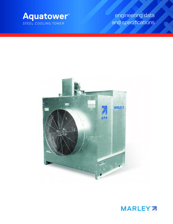
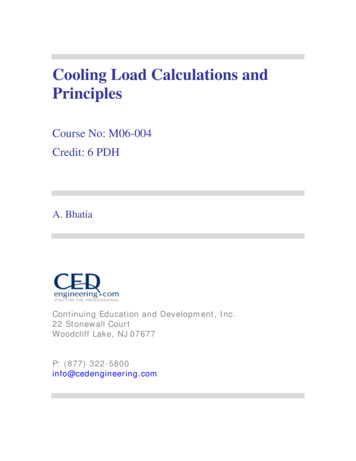
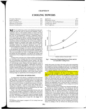
manufacturers use a variety of materials to construct cooling towers. Materials are chosen toenhance corrosion resistance, reduce maintenance, and promote reliability and long service life.Galvanized steel, various grades of stainless steel, glass fiber, and concrete are widely used intower construction, as well as aluminum and plastics for some components.Frame and casing. Wooden towers are still available, but many components are made of differentmaterials, such as the casing around the wooden framework of glass fiber, the inlet air louvers ofglass fiber, the fill of plastic and the cold-water basin of steel. Many towers (casings and basins)are constructed of galvanized steel or, where a corrosive atmosphere is a problem, the tower and/orthe basis are made of stainless steel. Larger towers sometimes are made of concrete. Glass fiber isalso widely used for cooling tower casings and basins, because they extend the life of the coolingtower and provide protection against harmful chemicals.Figure 2 frame of cooling tower3
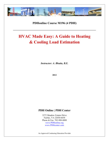
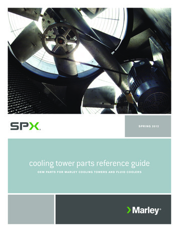
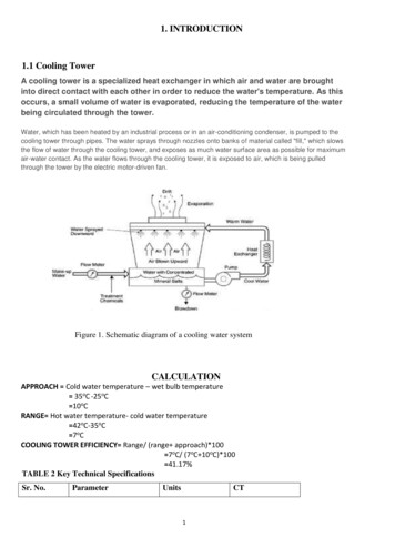
Figure 3 cooling tower casingFill. Plastics are widely used for fill, including PVC, polypropylene, and other polymers. Whenwater conditions require the use of splash fill, treated wood splash fill is still used in woodentowers, but plastic splash fill is also widely used. Because of greater heat transfer efficiency, filmfill is chosen for applications where the circulating water is generally free of debris that could blockthe fill passageways.Figure 4 FillsNozzles. Plastics are also widely used for nozzles. Many nozzles are made of PVC, ABS,polypropylene, and glass-filled nylon.Figure 5 NozzleFans. Aluminum, glass fiber and hot-dipped galvanized steel are commonly used fan materials.Centrifugal fans are often fabricated from galvanized steel. Propeller fans are made from galvanizedsteel, aluminum, or molded glass fiber reinforced plastic.4
Figure 6 cooling fan2.2 Mechanical draft cooling towerMechanical draft towers have large fans to force or draw air through circulated water. The waterfalls downwards over fill surfaces, which help increase the contact time between the water and theair - this helps maximize heat transfer between the two. Cooling rates of mechanical draft towersdepend upon various parameters such as fan diameter and speed of operation, fills for systemresistance etc. Mechanical draft towers are available in a large range of capacities. Towers can beeither factory built or field erected - for example concrete towers are only field erected. Manytowers are constructed so that they can be grouped together to achieve the desired capacity. Thus,many cooling towers are assemblies of two or more individual cooling towers or "cells." Thenumber of cells they have, e.g., a eight-cell tower, often refers to such towers. Multiple-cell towerscan be lineal, square, or round depending upon the shape of the individual cells and whether theair inlets are located on the sides or bottoms of the cells. The three types of mechanical draft towersare summarized in (Table 1).Figure 9. Induced draft counter flow cooling tower5
Figure 10. Induced draft cross flow cooling tower3. ASSESSMENT OF COOLING TOWERSThis section describes how the performance of cooling powers can be assessed. Theperformance of cooling towers is evaluated to assess present levels of approach and range againsttheir design values, identify areas of energy wastage and to suggest improvements.During the performance evaluation, portable monitoring instruments are used to measure thefollowing parameters: Wet bulb temperature of air Dry bulb temperature of air Cooling tower inlet water temperature Cooling tower outlet water temperature Exhaust air temperature Electrical readings of pump and fan motors Water flow rate Air flow rateThese measured parameters and then used to determine the cooling tower performance inseveral ways. (Note: CT cooling tower; CW cooling water). These are:a) Range (see Figure 7). This is the difference between the cooling tower water inlet and outlettemperature. A high CT Range means that the cooling tower has been able to reduce thewater temperature effectively, and is thus performing well. The formula is:CT Range ( C) [CW inlet temp ( C) - CW outlet temp ( C)]b) Approach (see Figure 7). This is the difference between the cooling tower outlet cold watertemperature and ambient wet bulb temperature. The lower the approach the better the coolingtower performance. Although, both range and approach should be monitored, the ' Approach' isa better indicator of cooling tower performance.6
CT Approach ( C) [CW outlet temp ( C) - Wet bulb temp ( C)]c) Effectiveness. This is the ratio between the range and the ideal range (in percentage), i.e.difference between cooling water inlet temperature and ambient wet bulb temperature, or inother words it is Range / (Range Approach). The higher this ratio, the higher the coolingtower effectiveness.CT Effectiveness (%) 100 x (CW temp - CW out temp) / (CW in temp - WB temp)d) Cooling capacity. This is the heat rejected in kCal/hr or TR, given as product of mass flow rateof water, specific heat and temperature difference.e) Evaporation loss. This is the water quantity evaporated for cooling duty. Theoreticallythe evaporation quantity works out to 1.8 m3 for every 1,000,000 kCal heat rejected. Thefollowing formula can be used (Perry):Evaporation loss (m3/hr) 0.00085 x 1.8 x circulation rate (m 3/hr) x (T1-T2) T1 - T2 temperature difference between inlet and outlet waterf) Cycles of concentration (C.O.C). This is the ratio of dissolved solids in circulating water to thedissolved solids in makeup water.g) Blow down losses depend upon cycles of concentration and the evaporation losses and is givenby formula:Blow down Evaporation loss / (C.O.C. - 1)h) Liquid/Gas (L/G) ratio. The L/G ratio of a cooling tower is the ratio between the water andthe air mass flow rates. Cooling towers have certain design values, but seasonal variationsrequire adjustment and tuning of water and air flow rates to get the best cooling towereffectiveness. Adjustments can be made by water box loading changes or blade angleadjustments. Thermodynamic rules also dictate that the heat removed from the water must beequal to the heat absorbed by the surrounding air. Therefore the following formulae can be used:i) L (T1 - T2) G (h2 - h1) L/G (h2 - h1) / (T1 - T2)Where:L/G liquid to gas mass flow ratio (kg/kg)T1 hot water temperature ( C)T2 cold-water temperature ( C) h2 enthalpy of air-water vapor mixture at exhaust wetbulb temperature (same units as above)h1 enthalpy of air-water vapor mixture at inlet wet-bulb temperature.84. ENERGY EFFICIENCY OPPORTUNITIESThis section includes main areas for improving energy efficiency of cooling towers. The main areasfor energy conservation include: Selecting the right cooling tower (because the structural aspects of the cooling tower cannot7
be changed after it is installed) Fills Pumps and water distribution system Fans and motors4.1 Selecting the right cooling towersOnce a cooling tower is in place it is very difficult to significantly improve its energyperformance. A number of factors are of influence on the cooling tower's performance and shouldbe considered when choosing a cooling tower: capacity, range, approach, heat load, wet bulbtemperature, and the relationship between these factors. This is described below.4.1.1 CapacityHeat dissipation (in kCal/hour) and circulated flow rate (m 3/hr) are an indication of the capacityof cooling towers. However, these design parameters are not sufficient to understand the coolingtower performance. For example, a cooling tower sized to cool 4540 m 3 /hr through a 13.9 Crange might be larger than a cooling tower to cool 4540 m3/hr through 19.5 C range. Thereforeother design parameters are also needed.4.1.2 RangeRange is determined not by the cooling tower, but by the process it is serving. The range at theexchanger is determined entirely by the heat load and the water circulation rate through theexchanger and going to the cooling water. The range is a function of the heat load and the flowcirculated through the system:Range C Heat load (in kCal/hour) / Water circulation rate (l/hour)Cooling towers are usually specified to cool a certain flow rate from one temperature to anothertemperature at a certain wet bulb temperature. For example, the cooling tower might be specifiedto cool 4540 m3/hr from 48.9 C to 32.2 C at 26.7 C wet bulb temperature.4.1.3 ApproachAs a general rule, the closer the approach to the wet bulb, the more expensive the cooling towerdue to increased size. Usually a 2.8 C approach to the design wet bulb is the coldest watertemperature that cooling tower manufacturers will guarantee. When the size of the tower has tobe chosen, then the approach is most important, closely followed by the flow rate, and the rangeand wet bulb would be of lesser importance.Approach (5.5 C) Cold-water temperature 32.2 C - Wet bulb temperature (26.7 )4.1.4 Heat loadThe heat load imposed on a cooling tower is determined by the process being served. The degreeof cooling required is controlled by the desired operating temperature of the process. In mostcases, a low operating temperature is desirable to increase process efficiency or to improve thequality or quantity of the product. However, in some applications (e.g. internal combustion8
engines) high operating temperatures are desirable. The size and cost of the cooling tower isincreases with increasing heat load. Purchasing undersized equipment (if the calculated heat load istoo low) and oversized equipment (if the calculated heat load is too high) is something to be awareof Process heat loads may vary considerably depending upon the process involved and aretherefore difficult to determine accurately. On the other hand, air conditioning andrefrigeration heat loads can be determined with greater accuracy.4.1.5 Wet bulb temperatureWet bulb temperature is an important factor in performance of evaporative water coolingequipment, because it is the lowest temperature to which water can be cooled. For this reason, thewet bulb temperature of the air entering the cooling tower determines the minimum operatingtemperature level throughout the plant, process, or system. The following should be consideredwhen pre-selecting a cooling tower based on the wet bulb temperature:Theoretically, a cooling tower will cool water to the entering wet bulb temperature. In practice,however, water is cooled to a temperature higher than the wet bulb temperature because heat needsto be rejected from the cooling tower. A pre-selection of towers based on the design wet bulb temperature must considerconditions at the tower site. The design wet bulb temperature also should not beexceeded for more than 5 percent of the time. In general, the design temperature selected isclose to the average maximum wet bulb temperature in summer. Confirm whether the wet bulb temperature is specified as ambient (the temperature in thecooling tower area) or inlet (the temperature of the air entering the tower, which is oftenaffected by discharge vapors recycled into the tower). As the impact of recirculationcannot be known in advance, the ambient wet bulb temperature is preferred. Confirm with the supplier if the cooling tower i s able to deal with the effects ofincreased wet bulb temperatures.4.2 Fill media effectsIn a cooling tower, hot water is distributed above fill media and is cooled down throughevaporation as it flows down the tower and gets in contact with air. The fill media impacts energyconsumption in two ways: Electricity is used for pumping above the fill and for fans that create the air draft. Anefficiently designed fill media with appropriate water distribution, drift eliminator, fan,gearbox and motor with therefore lead to lower electricity consumption. Heat exchange between air and water is influenced by surface area of heat exchange,duration of heat exchange (interaction) and turb
tower performance. For example, a cooling tower sized to cool 4540 m3/hr through a 13.9 C range might be larger than a cooling tower to cool 4540 m3/hr through 19.5 C range. Therefore other design parameters are also needed. 4.1.2 Range Range is determined not by the cooling tower, but by the process it is serving. The range at the