Transcription
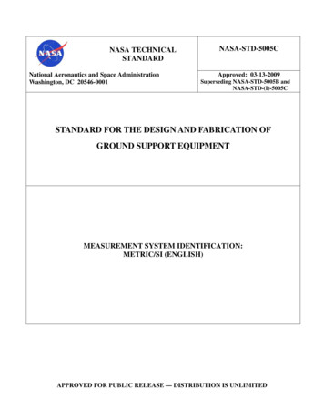
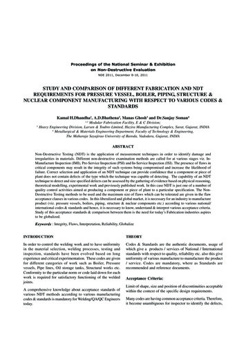
International Journal of Latest Engineering Research and Applications (IJLERA) ISSN: 2455-7137Volume – 02, Issue – 05, May – 2017, PP – 27-37Design and Fabrication of Cooling TowerDileep KJ1, Dileep Kumar Baniya2, Anoop Chandran Kurup3, Arun Varghese41234(Department of Mechanical Engineering, Bangalore Technological Institute,India)Abstract: Cooling tower is a heat rejection device. It is used to dissipate waste heat into the atmosphere. Thispaper is all about the developing a cooling tower that cools the hot water coming from the different equipmentin energy conversion lab. In energy conversion lab, there are total five equipments from which we are gettinghot water while conducting the experiment. Due to hotness the water is not suitable for experimentation. So thehot water is directly released into the ground without being recirculated. This necessitates the development ofcooling tower to cool the water. For this purpose a tank used where the hot water coming from the differentequipment gets collected. The hot water is then supplied to the cooling tower for cooling by the use of motorpump. The cooling effect is obtained by the natural air which is entering in the gap provided by the louvers.After the water is cooled it gets collected in another tank which is kept at the bottom of the cooling tower. Thecooled water is recirculated into the equipment for conducting the experiment.Keywords: Cooling tower, Equipment, Louver, Motor pump, Tank.1. IntroductionA cooling tower is a heat rejection device which extracts waste heat to the atmosphere through thecooling of a water stream to a lower temperature. Cooling towers may either use the evaporation of water toremove process heat and cool the working fluid to near the wet-bulb air temperature or, in the case of closedcircuit dry cooling towers, rely solely on air to cool the working fluid to near the dry-bulb air temperature.In energy conversion lab there are five different engine in which experiment is conducted. Theseengine require cold water for conducting the experiment. After successfully completion of experiment hot watercomes out from the engine as bi product. Since the water coming from the engines are hot, so this water is notsuitable to use in the lab. So this water is discharged in the ground as a waste behind the lab.To utilize the wateragain or to overcome from the water problem, a cooling tower is developed. This cooling tower will do the workof reducing the water temperature. The water coming from the different engine will be supplied into the coolingtower and after cooling is done again it is supplied into the main stream.The tower provides a horizontal air flow as the water falls down the tower in the form of smalldroplets. The fan centered at the top of units draws air through two cells that are paired to a suction chamberpartitioned beneath the fan. The outstanding feature of this tower is lower air static pressure loss as there is lessresistance to air flow. The evaporation and effective cooling of air is greater when the air outside is warmer anddryer than when it is cold and already saturated.Originally, cooling towers were constructed primarily with wood, including the frame, casing, louvers,fill and cold-water basin. Sometimes the cold water basin was made of concrete. Today, manufacturers use avariety of materials to construct cooling towers. Materials are chosen to enhance corrosion resistance, reducemaintenance, and promote reliability and long service life. Galvanized steel, various grades of stainless steel,glass fiber and concrete are widely used in tower construction, as well as aluminium and plastics for somecomponents. Fig. 1 shows the proposed model of cooling tower.Fig. 1 proposed modelwww.ijlera.com2017 IJLERA – All Right Reserved27 Page
International Journal of Latest Engineering Research and Applications (IJLERA) ISSN: 2455-7137Volume – 02, Issue – 05, May – 2017, PP – 27-372. Literature surveySeetharamu and Swaroop [1], has found the effect of size on the performance of a fluidized bed coolingtower. Application of the principles of the fluidization is made for cooling towers. The performance on a smallersize Fluidized Bed Cooling Tower (FBCT) is found to be encouraging. Hence a larger size FBCT is designedand the performance is found to be equally good. The pressure drop encountered in FBCT is comparable to thatof conventional cooling towers. The packing height in FBCT reduces considerably because of fluidization.Experiments are conducted in two sizes of tower column. In the smaller tower ambient air is forced into the testsection by a blower through a diffuser and suitable turning vanes to have a uniform air flow distribution. Theflow is regulated by a throttle control valve fitted at the discharge of the blower section. Water is heated in alarge tank fitted with electric heaters and fed to the tower. A spray nozzle is used for uniform distribution of hotwater in to the test section. The water flow is regulated by a control valve. The cooled water collected in thebasin and returned back to the tank for recirculation. Air flow is measured by a flow nozzle placed at the entryto the blower. Water flow is measured by a orifice plate with differential mercury manometer at the hot waterentry to the tower. Trappings are provided to fit thermocouples and also to make pressure drop readings. Digitalmultivoltmeters and multiple junction manometers are used for their measurements. A back up thermometer isused for temperature measurement. Psychrometer is used for wet bulb and dry bulb temperature measurements.Ramkumar and Ragupathy [2],did Experiment on the thermal performance of forced draft counter flowwet cooling tower with expanded wire mesh type packing. The packing used in this work is VerticalOrientations Wire Mesh Packing (VOWMP) and Horizontal Orientations Wire Mesh Packing (HOWMP). Thepacking is 1.25 m height and having a zigzag form. From the experiments it is concluded that the verticalorientation of the packing enhance the performance of the cooling tower. Performance of the cooling tower wasanalyzed with expanded wire mesh packing with two different orientations. From the experimental results, theVOWMP is having better performance than HOWMP. It is due water passing over the flank angle of the wiremesh fills and fine water droplets formed in the VOWMP. In VOWMP the water droplets are split into fine sizecompared with HOWMP. The air to water contact is more in VOWMP, so better heat transfer has been occurredand the cooling water outlet temperature is reduced compared with HOWMP. From the experimental study theefficiency of the cooling tower and cooling tower characteristics are higher in VOWMP due to higher contactarea of water to air. Up to 0.8 Liquid/Gas (L/G) ratio because of better contact area between airs to water thedrop in performance of the cooling tower is less. Above 0.8 L/G ratio, the cooling tower performance wasdecreased drastically due to large quantity of water and lesser quantity of air. For that reason the contact areabetween airs to water is in improper ratio. The L/G ratio up to 0.8, the VOWMP performance is good and over0.8 L/G the performance is dropdown. The present study can be extended with different pitch of the mesh anddifferent size of the diamonds shape.Nagam and Hayder [3], they found experimentally and theoretically heat and mass transfercharacteristics of the cooling tower. Through experimentation they absorbed the variation of outlet airtemperature with air flow rate at different inlet water temperature tends to decrease with increasing air flow rate.However, for high air flow rate region, decreasing rate of outlet air temperature decreases. At specific air andwater flow rates and inlet air temperature, effect of inlet water temperature on the outlet air temperature is verysmall. The reasonable agreement is obtained from the comparison between the predicted results and the presentexperimental data. It can be seeing that the model give high accuracy relatively with real results (experimentresults). The tower effectiveness increased with the temperature ratio because the outlet water temperaturedecreases as airflow rate increases number of transfer unit increases as the temperature ratio increases atdifferent L/G. However, trends of curves become cajole as L/G decreases. The pressure drop increasing withincreasing airflow rate at different temperature. Variation of outlet air temperature with airflow rate at differentinlet water temperature tends to decrease with increasing airflow rate.3. Design of cooling towerThe design of cooling tower is based on the following parameterMass flow rate 10 LPM 10 60 LPHMass flow rate 600 LPHMass flow rate 1.667 10 -4 m3 /secMass flow rate 1.667 10-4 1000Mass flow rate 0.1667 Kg/secWhere 1 m3/sec 1000 Kg / secSurrounding condition 5% WBT & 28º CTaking 80% load condition the average temperature of hot water coming from the engine is 65º C.Water inlet temperature from cooling tower, T 1 65º Cwww.ijlera.com2017 IJLERA – All Right Reserved28 Page
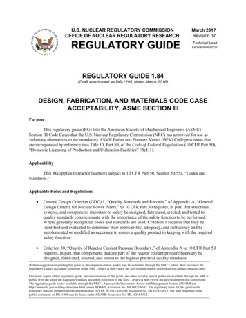
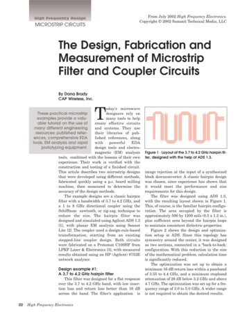
International Journal of Latest Engineering Research and Applications (IJLERA) ISSN: 2455-7137Volume – 02, Issue – 05, May – 2017, PP – 27-37Assuming, Water outlet temperature to cooling tower, T 2 60º CAssumption, tower base dimension 1 m 1 mFan capacity 0.36 m3/ secStep: 1 Water loading (L)Mass flow rateWater loading: L AreaMass flow rate, M 0.1667 Kg/secTower Area, A 1 m 1 m 1 m20.1667L 1L 0.1667 kg/m2secFan CapacityStep: 2 Air loading: G Density (air water)G ρa w FCA(1)(2)Tower Area ρa w1[Va w Sp. vol. of air water]V a wFrom Table 17.2 (from data handbook)When temp of air 28º C, V 0.8939 m3/kg1ρa w 1.1186 kg/m30.89390.36G 1.1181G 0.402719 kg/m2-secStep: 3 Enthalpies and humidity of air water mixtureFrom Table 17.2When temp of air 29.44º C: enthalpy 116.3 KJ/ kgWhen temp of air 32.22º C: enthalpy 131.884 3 KJ/ kgEnthalpy at 30º C is given by interpolation methodLet enthalpy at 30º C be x. then by interpolation methodx 116 .330 29.44 131 .884 116 .332.22 29.44X H1 119.43 KJ/ kgStep: 4 EnthalpiesLH2 H1 (T1 – T2)GWater loadingAir loading:LG 0.16670.402719(3) 0.4133H2 119.43 0.4133 (65-60) 121.49 KJ/ kgTABLE 1 shows the effect of temperature on enthalpy. It shows the value of of ºC, H’, H, (H’-H), (H’-H)avg, dtw/(H’-H)avgTable 1Effect of temperature on enthaplyHH2 H1 L/G x H’Enthalpy of .0114Temp ºCStep: 5 Number of diffusion units: nd kaVLStep: 7 Height of diffusion units: HDU www.ijlera.com d twH’ H avg 0.01144𝑍𝑛𝑑2017 IJLERA – All Right Reserved(4)29 Page
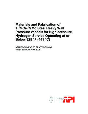
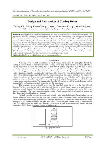
International Journal of Latest Engineering Research and Applications (IJLERA) ISSN: 2455-7137Volume – 02, Issue – 05, May – 2017, PP – 27-37Where, Transfer unit: Z 0.01144nd L(5)kaV 0.1667Z 1.9 10-3𝑍HDU Z 1𝑛𝑑1.9 10 3 0.01144 1.66 mFig. 2 shows the 3d model of the cooling tower and Fig. 3 shows the assemblies of the sub components.Fig. 2 3D model of cooling towerFig. 3 assemblies of the sub component4. Working principleThe working principles makes use of tank, pump, cooling tower and reservoir (for collecting the water)for cooling purpose. The cooled water from the tank is supplied into the equipment for conducting theexperiment. When the experiment is conducted successfully the water coming out of the equipment becomes hotand the water has to be cooled for re conducting the experiment and this is achieved by the help of coolingtower. The main task of the cooling tower is to cool the water. For cooling of water, first of all, the hot waterscoming through the different equipments are collected into the tank through the use of pipe. Now, the hot waterfrom the tank is supplied into the cooling tower with the help of water pump.The water is passed into the cooling tower through the pipe and sprayed from the top of the coolingtower with the help of nozzle. Nozzle helps in proper distribution of the water all around the cooling tower sothat effective cooling is obtained. As the water falls down it comes in contact with the natural air which isentering into the cooling tower through the gap provided between the louvers. When the water comes in contactwith the air, heat transfer takes place between the hot water and the cold air. As soon the air gets heated it risesup and comes out of the cooling tower through the exhaust fan.www.ijlera.com2017 IJLERA – All Right Reserved30 Page
International Journal of Latest Engineering Research and Applications (IJLERA) ISSN: 2455-7137Volume – 02, Issue – 05, May – 2017, PP – 27-37At the bottom of the cooling tower thermocol are bed are placed. Thermocol are basically polystyrenebed material that increases the contact between the cold air and the hot water so that maximum heat transfer cantake place. As the hot water gets cooled it passes through the cooling tower through the outlet provided and it iscollected in the reservoir or supplied to the main tank.5. Major componentsThe components used in the design of cooling tower are as follows:5.1Collecting tankIn this project two tanks are required. The first tank is required to collect the hot water coming from theenergy lab and the water from the same tank is supplied into the cooling tower. The second tank is required tocollect the cold water coming from the cooling tower. The tanks which we are using in this project are made uppolyethylene plastic to store the hot water coming from the equipment and also the cold water coming from thecooling tower. Both the tank provided in this project are having capacity to hold water up to 50 liters.5.2 Water pumpA pump is a device that moves fluids (liquids or gases), by mechanical action. Pumps can be clas
Abstract: Cooling tower is a heat rejection device. It is used to dissipate waste heat into the atmosphere. This paper is all about the developing a cooling tower that cools the hot water coming from the different equipment in energy conversion lab. In energy conversion lab, there are total five equipments from which we are getting