Transcription
H.264 Network DVRUser ManualGUI Display with USB Mouse ControlPlease read instructions thoroughly before operation and retain it for future reference.For the actual display & operation, please refer to your DVR in hand.中文 k679b 677b 674b c551b m759b 757b 751b 688b 686b a791b Manual V1.0
IMPORTANT SAFEGUARDCAUTIONRISK OF ELECTRIC SHOCKCAUTION:To reduce the risk of electric shock, do not expose this apparatus to rain or moisture. Only operate thisapparatus from the type of power source indicated on the label. The company shall not be liable for anydamages arising out of any improper use, even if we have been advised of the possibility of suchdamages.The lightning flash with arrowhead symbol, within an equilateral triangle, is intended to alert theuser to the presence of uninsulated “dangerous voltage” within the product’s enclosure that maybe of sufficient magnitude to constitute a risk of electric shock to persons.This exclamation point within an equilateral triangle is intended to alert the user to the presenceof important operating and maintenance (servicing) instructions in the literature accompanyingthe appliance.All lead-free products offered by the company comply with the requirements of the European lawon the Restriction of Hazardous Substances (RoHS) directive, which means our manufactureprocesses and products are strictly “lead-free” and without the hazardous substances cited in thedirective.The crossed-out wheeled bin mark symbolizes that within the European Union the product mustbe collected separately at the product end-of-life. This applies to your product and anyperipherals marked with this symbol. Do not dispose of these products as unsorted municipalwaste. Contact your local dealer for procedures for recycling this equipment.This apparatus is manufactured to comply with the radio interference requirements.Federal Communications Commission Interference StatementThis equipment has been tested and found to comply with the limits for a Class A digital device, pursuant to Part15 of the FCC Rules. These limits are designed to provide reasonable protection against harmful interferencewhen the equipment is operated in a commercial environment. This equipment generates, uses, and can radiateradio frequency energy and, if not installed and used in accordance with the instruction manual, may causeharmful interference to radio communications. Operation of this equipment in a residential area is likely to causeharmful interference in which case the user will be required to correct the interference at his own expense.Trademark AcknowledgementsiPhone is the registered trademark of Apple Inc.BlackBerry and related trademarks, names and logos are the property of Research In Motion Limited and areregistered and/or used in the U.S. and countries around the world. Used under license from Research In MotionLimited.Microsoft , Windows , Internet Explorer , Mozilla Firefox , Google Chrome , QuickTime , Windows Mobile & Symbian mentioned in this document are the registered trademarks of their respective holders.DisclaimerThe information in this manual was current when released. We reserve the right to revise or remove any content inthis manual at any time. We do not warrant or assume any legal liability or responsibility for the accuracy,completeness, or usefulness of this manual. For the actual display & operation, please refer to your DVR in hand.The content of this manual is subject to change without notice.
GroundingThis is a Safety Class 1 Product (provided with a protective earthing ground incorporated in the power cord). Themains plug shall only be inserted in a socket outlet provided with a protective earth contact. Any interruption of theprotective conductor inside or outside of the instrument is likely to make the instrument dangerous. Intentionalinterruption is prohibited.Water & MoistureDo not expose this product to dripping or splashing and that no objects filled with liquids, such as vases, shall beplaced on the product.MPEG4 LicensingTHIS PRODUCT IS LICENSED UNDER THE MPEG-4 VISUAL PATENT PORTFOLIO LICENSE FOR THEPERSONAL AND NON-COMMERCIAL USE OF A CONSUMER FOR (i) ENCODING VIDEO IN COMPLIANCEWITH THE MPEG-4 VISUAL STANDARD (“MPEG-4 VIDEO”) AND/OR (ii) DECODING MPEG-4 VIDEO THATWAS ENCODED BY A CONSUMER ENGAGED IN A PERSONAL AND NON-COMMERCIAL ACTIVITY AND/ORWAS OBTAINED FROM A VIDEO PROVIDER LICENSED BY MPEG LA TO PROVIDE MPEG-4 VIDEO. NOLICENSE IS GRANTED OR SHALL BE IMPLIED FOR ANY OTHER USE. ADDITIONAL INFORMATIONINCLUDING THAT RELATING TO PROMOTIONAL INTERNAL AND COMMERCIAL USES AND LICENSINGMAY BE OBTAINED FROM MPEG LA, LLC. SEE HTTP://WWW.MPEGLA.COM.GPL LicensingThis product contains codes which are developed by Third-Party-Companies and whichare subject to the GNU General Public License (“GPL”) or the GNU Lesser Public License(“LGPL”).The GPL Code used in this product is released without warranty and is subject to thecopyright of the corresponding author.Further source codes which are subject to the GPL-licenses are available upon request.We are pleased to provide our modifications to the Linux Kernel, as well as a few newcommands, and some tools to get you into the code. The codes are provided on the FTPsite, and please download them from the following site or you can refer to your distributor:http://download.dvrtw.com.tw/GPL/076D Series/arm-linux-2.6.tar.gz
TABLE OF CONTENTS1. BEFORE USING THIS DVR . 11.1 Package Content . 11.2 Front Panel . 11.3 Rear Panel . 22. CONNECTION AND SETUP . 42.1 SATA HDD Installation. 42.2 Camera Connection . 62.2.1 Normal Camera Connection . 62.2.2 PTZ Camera Connection (For Selected Models Only) . 72.3 DVR Power On . 82.4 Date and Time Setting. 92.5 Clear Hard Disk . 92.6 Password Setting . 103. GUI DISPLAY WITH USB MOUSE CONTROL . 113.1 Connect USB Mouse. 113.2 Quick Menu Bar . 113.2.1 Channel Switch . 123.2.2 PTZ Control Panel . 123.3 Main Menu . 134. BASIC OPERATION . 144.1 Live Page . 144.2 Record Icon. 144.3 Playback . 154.3.1 Playback Control. 154.3.2 Event Search . 164.3.3 Audio Playback . 164.4 User Level Switch . 165. FREQUENTLY-USED FUNCTIONS . 175.1 Quick Search . 175.2 Record . 185.2.1 Quick record setting . 185.2.2 Detailed record setting . 195.3 Schedule Setting . 205.3.1 Record Timer . 205.3.2 Detection Timer. 21
5.3.3 Alarm Timer . 215.4 Detection Setting . 225.5 PTZ Camera Setting . 235.6 System Setting . 245.6.1 Password Setting . 245.6.2 System Upgrade . 245.6.3 Backup & Restore Configurations . 255.6.4 Video Backup. 255.6.5 Event Log Backup. 275.6.6 Clear All HDD Data . 285.7 Network . 285.7.1 STATIC . 285.7.2 PPPOE . 295.7.3 DHCP . 305.7.4 DDNS . 305.8 Event Notifications . 315.8.1 FTP . 315.8.2 E-MAIL . 325.9 VGA Output Resolution Support . 326. REMOTE OPERATION. 336.1 Supplied Licensed Software . 336.1.1 Installation & Network Connection . 336.1.2 Control Panel Overview . 356.1.3. General Operation . 376.1.4. E-Map . 416.2 Web Browser . 466.2.1 Event Download & Playback . 48APPENDIX 1 SPECIFICATIONS . 50APPENDIX 2 COMPATIBLE USB FLASH DRIVE LIST . 56APPENDIX 3 COMPATIBLE SATA HDD LIST . 57APPENDIX 4 MAIN MENU STRUCTURE . 58APPENDIX 5 DVR BATTERY REPLACEMENT . 60APPENDIX 6 PIN CONFIGURATION . 61APPENDIX 7 DVD WRITER INSTALLATION . 64APPENDIX 8 DVD- / CD-ROM COMPATIBLE LIST . 65
BEFORE USING THIS DVR1. BEFORE USING THIS DVR1.1 Package Content¾¾Standard PackageDVRHDD screwsAdapter & Power cordCD ManualOptional AccessoriesIR Remote ControllerUSB MouseManual for IR Remote ControllerDSUB ConnectorIR Receiver Extension Cable1.2 Front Panel1)LED IndicatorsHDD is reading or recording.An alarm is triggered.Timer recording is on.Under playback status.DVR is powered on.2)( ) / ( ) / ( ) / ( )Press / / / to move up / down / left / right.In the playback mode:Press “ ” to pause playback.Press “ ” to stop playback.Press “ “ to fast forward.Press “ “ to fast rewind.3)MENUPress “MENU” to enter the main menu.4)ENTERPress “ENTER” to confirm the setting.5)LIST (Event List Search)Press to quickly search the recorded files by event lists: RECORD / MOTION / ALARM /TIME, or select FULL to show all the event logs.To quickly search the time you want, select “QUICK SEARCH”. Set the time range youwant, and select “SUBMIT” to play the recorded video clip during the specified time.6)PLAYPress to playback the latest recorded data.1
BEFORE USING THIS DVR7)SLOWIn the playback mode, press to show slow playback.8)ZOOMPress to enlarge the picture of selected channel in the FRAME or FIELD recordingmode.9)SEQPress to display each channel in full screen one by one starting from CH1. When the lastchannel is displayed, it will repeat from CH1 again. To exit this mode, press “SEQ”again.10)Press to show the 4-channel display mode.11) CH1 16 / 1 8 / 1 4Press the channel number keys to select the channel to display.12) SEARCH (For Selected Models Only)Press to enter the time search menu. Set the time range you want, and select “START”to play the recorded video clip during the specified time.13) AUDIO (SLOW ZOOM)Press “SLOW” “ZOOM” to select live or playback audio from audio channel 1 4.Live audio from audio channel 1 4(indicated in white)Playback audio from audio channel 1 4(indicated in yellow)Audio channel unselected14) P.T.Z. (Press “ SEQ)” “SEQ” at the same time to enter / exit the PTZ control mode.15) USB portThere are two USB ports on the front panel, one for connecting your USB mouse formouse control, and the other one for connecting your USB flash drive for video backup.Note: It’s not allowed to have two USB mice or two USB flash drives connected onthe front panel.For the compatible USB flash drive list, please refer to “APPENDIX 2 COMPATIBLEUSB FLASH DRIVE LIST” at page 56.16)(For selected models only)Press “ ” to open / close the DVD writer.1.3 Rear Panel1)75Ω / HI-IMPEDANCE (For Selected Models Only)When using Loop function, please switch to HI-IMPEDANCE. When you don’t use Loop2
BEFORE USING THIS DVRfunction, please switch to 75Ω.2)VIDEO IN (1 16 / 1 8 / 1 4): Connect to the video connector of a camera.VIDEO LOOP (1 16 / 1 8): Video output connector. (For Selected Models Only)Note: The DVR will automatically detect the video system of the camera, pleasemake sure that the cameras are properly connected to the DVR andpower-supplied before the DVR is turned on.3)AUDIO IN (1 4)Connect to the audio connector of a camera if the camera supports audio recording.Note: To make a video backup with audio, make sure the camera which supportsthe audio function is connected to the video-in channel and audio-inchannel. For example, the audio data from audio CH1 will be recorded withthe video data from video CH1.4)AUDIO OUTConnect to a speaker with 1 mono audio output.Note: To know how many audio outputs your DVR supports, please refer to itsspecifications.5)MONITORConnect to a CRT monitor for video output.6)CALL (For Selected Models Only)Connect to a monitor specific for sequence display.7)VGAConnect to a LCD monitor directly.8)IR (For Selected Models Only)Connect the optional IR receiver extension cable for remote control.9)EXTERNAL I/OThis port is used to connect external devices (such as speed dome cameras or externalalarm, etc).For detailed I/O port PIN configuration, please refer to “APPENDIX 6 PINCONFIGURATION” at page 61.10) LANConnect to Internet by LAN cable.11) DC 19VConnect to the supplied adapter.12)Power SwitchSwitch to “\” to turn on the power, and “ ” to turn off the power.3
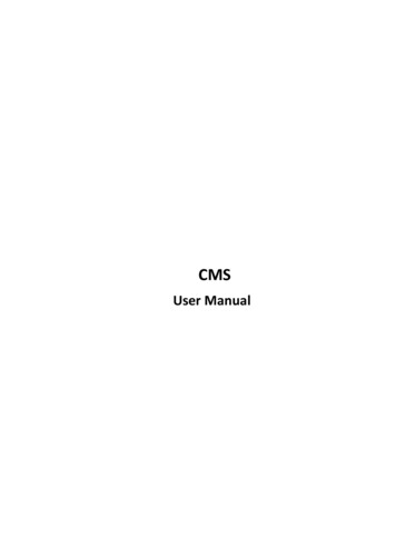
CONNECTION AND SETUP2. CONNECTION AND SETUPBefore the DVR is powered on, make sure you have installed a hard disk and connectedat least one camera. For details, please refer to the following sections.Note: The DVR is designed to automatically detect the video system of theconnected cameras (NTSC or PAL). To make sure the system detection iscorrect, please check if the cameras are connected to the DVR andpower-supplied before the DVR is powered on.2.1 SATA HDD InstallationA SATA HDD must be installed before the DVR is powered on.Note: It’s recommended to clear all data in the hard disk when the DVR ispowered on and the date & time are set correctly to ensure the recordeddata are not mixed with other data previously saved in the same hard disk.For details, please refer to “5.6.6 Clear All HDD Data” at page 27.¾For 2-HDDs ModelsStep1: Loose the screws on the upper cover and open the upper cover of the DVR.Note: The DVR cover is made of metal. Please be careful with its edge when youremove the cover.Step2: There are two HDD brackets for thisDVR as indicated on the right picture.2-1 To install on the first bracketRemove the bracket, and align thescrew holes of the bracket with theHDD’s screw holes. Make sure thePCB side of the HDD is facing up.Fasten the HDD to the bracket, andconnect the power connector anddata bus connector to the HDD.Then, replace the bracket to DVR.4
CONNECTION AND SETUP2-2 To install on the second bracketConnect the power connector anddata bus connector to the HDD.When connecting the power cable,make sure the cable is passedthrough the power cable of DVDwriter if your DVR is equipped witha DVD writer. This is to prevent theHDD power cable from interferingwith the fan spinning.Align the screw holes of the bracketwith the HDD’s screw holes. Makesure the PCB side of the HDD isfacing up. Then, fasten the HDD tothe bracket.Note: For DVD writer installation, please refer to “APPENDIX 7 DVD WRITERINSTALLATION” at page 64.Step3: Close the upper cover of the DVR, and fasten all the screws you loosened inStep1.¾For 1-HDD ModelStep1: Loose the screws on the upper cover and remove it from the DVR. Find the twoHDD b
Grounding This is a Safety Class 1 Product (provided with a protective earthing ground incorporated in th