Transcription
OPERATING MANUALMODEL 4207DDIGITAL COMPRESSIVESTRENGTH TESTERRevision M – November 2015P/N: 89-0164S/N:2001 N. Indianwood Ave.Broken Arrow, Oklahoma 74012 U.S.A.Telephone: 918-250-7200Fax: 918-459-0165E-mail: chandler.sales@ametek.comWebsite: http://www.chandlereng.com
Copyright 2015, by Chandler Engineering Company, LLCP.O. Box 470710Tulsa, Oklahoma 74147All rights reserved. Reproduction or use of contents in any manner is prohibited without express permission from Chandler EngineeringCompany, LLC. While every precaution has been taken in the preparation of this manual, the publisher assumes no responsibility for errors oromissions. Neither is any liability assumed for damages resulting from the use of the information contained herein.This publication contains the following trademarks and/or registered trademarks: AMETEK, CHANDLER ENGINEERING. These trademarksor registered trademarks and stylized logos are all owned by AMETEK, Inc. All other company, product and service names and logos aretrademarks or service marks of their respective owners.
TABLE OF CONTENTST-1Table of ContentsGeneral Information . P-1Introduction. P-1Purpose and Use . P-1Description . P-1Features and Benefits . P-1Specifications . P-1Safety Requirements . P-2Safety Features . P-2Where to Find Help . P-3Section 1 – Installation . 1-1Unpacking the System. 1-1Utilities Required . 1-1Tools/Equipment Required . 1-1Connecting Power . 1-1Connecting the Press to the Power Unit . 1-2Connecting to a Data Acquisition System . 1-2Serial Data Connection . 1-2Section 2 - Operating Instructions . 2-1Programming the Controller . 2-1Sample Controller Program . 2-2Configuring the Display . 2-3Operating Procedure. 2-4Interpreting the Results . 2-6API Cement Compressive Strength Test . 2-6Section 3 – Maintenance. 3-1Maintenance Schedule . 3-1Filling the Oil Reservoir . 3-1Adjusting the System Pressure . 3-1Resetting the Maximum Temperature Limit . 3-2Maintaining the Press Assembly . 3-3Maintaining the Hydraulic Power Unit . 3-3Adjusting the Platen Control Switch . 3-3Calibration . 3-4Load Cell and Display and Controller Calibration . 3-4Controller Calibration. 3-5
T-2TABLE OF CONTENTSSection 4 - Troubleshooting Guide . 4-1Section 5 - Replacement Parts .5-1Section 6 – Drawings and Schematics . 6-1
PREFACEP-1General InformationIntroductionThe Model 4207D Digital Compressive Strength Tester is a hydraulic press system that maybe used to apply known compressive loads to a sample at known rates. The maximum load is50,000 Lbf. The Model 4207D Tester meets all the requirements for cement compressivetesting as specified in API Specification 10.Purpose and UseThe Model 4207D Compressive Strength Tester is designed to test the compressive strengthof sample cement cubes in compliance with API Specification 10. The Model 4207Denables the operator to achieve steady, uniform loading of the sample in order to obtain anaccurate measure of the compressive strength.DescriptionThe sample load schedule is programmable as a series of ramps and dwells using a controller.The system is equipped with a digital display that retains the maximum load that causes thefailure of the sample under test.Features and Benefits Programmable loading rates from 500 to 10,000 psi/min (2000 to 40,000 Lbf/min)Maximum load of 50,000 LbfPolycarbonate safety shield with door safety interlockMultiple load rates/durations can be programmed as a single control operationPrecise rate control electronic system and hydraulic pressure release valves providingoutstanding control of the loading rateInterface to Model 5270 Data Acquisition and Control Software (used to acquire andplot the results)SpecificationsPower Requirements:200-240 VAC, 50 Hz or 60 HzMaximum Load:50,000 pounds-force (Lbf), 222 kNMaximum Loading Rate:40,000 Lbf/Minute (178 kN/min)Maximum Load Dwell:3 min @ 50,000 Lbf (222 kN) with initial oil temperaturebelow 75oF (24oC)175oF (60oC)Maximum Oil Temperature:Environmental:40-120oF (4-49oC)95% Relative Humidity (non-condensing)
P-2PREFACESerial Interface:Modbus-RTU ProtocolHydraulic Fluid:SAE 10W30 Synthetic OilShipping Dimensions:Load Frame48” (122 cm) high x 24” (61 cm) wide x 28” (71 cm) deepControl Cabinet54” (138 cm) high x 28” (71 cm) wide x 30” (76 cm) deepNet Weight:Load FrameControl Cabinet360 lbs (164 kg)570 lbs (260 kg)Safety RequirementsNote: Before attempting to operate the instrument, the operator should read andunderstand this manual.The Chandler Engineering Model 4207D Digital Compressive Strength Tester is designed foroperator safety. Any instrument that is capable of high pressures should always be operatedwith CAUTION!!To ensure safety: Locate the instrument in a low traffic area.Post signs where the instrument is being operated to warn non-operating personnel.Read and understand instructions before attempting instrument operation.Observe caution notes!Observe and follow the warning labels on the instrument.Never exceed the instrument maximum temperature ratings.Always disconnect main power to the instrument before attempting any repair.Appropriately rated fire extinguishers should be located within close proximity.Only trained personnel should operate the system.The system should never be operated while unattended.All personnel using the system should wear safety glasses.The system must be located in a safe environment.All safety interlocks must be operational and properly adjusted.The system must be properly maintained and any defective components serviced orreplaced.Safety Features Door interlock switch: Prevents the operation of the system when the press door is open.Over temperature safety circuit: Prevents the operation of the system if the oiltemperature exceeds the specified limit.
PREFACE P-3Automatic system shut-down: The controller automatically terminates the active programwhen the sample fails.Where to Find HelpIn the event of problems, your local sales representative will be able to help or you cancontact the personnel at Chandler Engineering using the following: Telephone:918-250-7200 FAX:918-459-0165 E-mail:chandler.sales@ametek.com Website:www.chandlereng.com
P-4PREFACEThis page is intentionally left blank
SECTION 1 – INSTALLATION1-1Section 1 – InstallationUnpacking the SystemCarefully unpack the Model 4207D and all of its accessories. Visually inspect for anydamage that may have occurred during shipping. After the instrument is removed from theshipping crate, the equipment and spare parts should be checked against the packing list toinsure that all parts have been received and none are damaged.Remove the front cover of the instrument to remove the circuit board and spare parts that areindividually wrapped to prevent damage during shipment. Slide the circuit board into thebackplane as illustrated below; then replace the front cover.Note: File an insurance claim with your freight carrier if damage has occurredduring shipping. Verify all parts shown on the enclosed packing list have beenreceived. If items are missing, please notify Chandler Engineeringimmediately.Utilities RequiredElectrical:200-240 VAC, 50 Hz or 60 Hz, depending on model.Tools/Equipment RequiredNo special tools are required for the installation of the Model 4207D. Standard hand toolsare sufficient.Connecting PowerConnect the power cord to an approved grounded receptacle in accordance with local wiringcodes. Model 4207D-60Hz is intended for use on, 200-240 VAC 60 Hz and Model 4207D50Hz is intended for use on, 200-240 VAC 50 Hz.
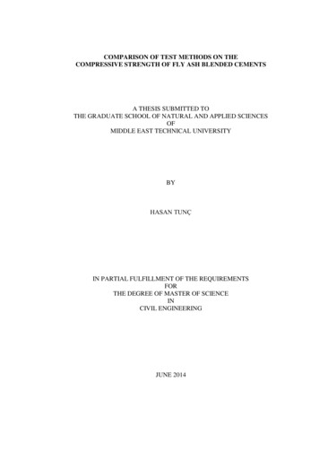
1-2SECTION 1 – INSTALLATIONThe system power switch on the front panel also serves as a circuit breaker. If the breakertrips, correct the electrical problem then reset the breaker by cycling the switch.Connecting the Press to the Power UnitThere are three connections between the load frame and the control cabinet, 2 hydraulic linesand a 25-pin cable connection.1. Connect the two hydraulic lines to the quick-connect fittings on the left side of thecontrol cabinet. Make certain that the hydraulic connections are fully coupled. The hosefrom the bottom of the cylinder is connected to the bottom connection on the controlcabinet.2. Connect the cable between the two 25-pin connectors located on the load frame and thecontrol cabinet. The cable connections are labeled with a RED circle.3. Assemble the bottom platen and load cell in accordance with the illustration below:Top MandrelLoad CellLowerMandrelPlatenConnecting to a Data Acquisition SystemSerial Data ConnectionThe control cabinet includes a 25-pin connector on the left of the enclosure that is used forcommunications with the optional Chandler Engineering Model 5270 Data Acquisition andControl Software. The cable connections are labeled with a BLUE circle. A cable issupplied with the unit.
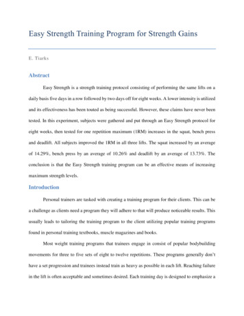
SECTION 2 – OPERATING INSTRUCTIONS2-1Section 2 - Operating InstructionsBefore operating the 4207D it is necessary to be familiar with the press controller and loadindicator features and controls.Programming the ControllerThe Model 7052 controller used with the 4207D system features user defined segmentprogramming (8 segments maximum). Using these segments, sample load ramp and dwellsegments are defined.Controller FeatureOutput 1 or 2:Upper Readout(Process Value)Lower Readout or(Setpoint Value)Remote CommunicationAuto/Manual ButtonRun/Hold ButtonPage ButtonScroll Button:Up/Down Buttons:Setpoint 2Description of FeatureNot active.Displays the current value of the sample load. Thisvalue must be multiplied by 10 to indicate poundsforce (Lbf).Indicates the current set point value. Indicates alarmcondition in the event of an alarm.Indicates remote communication if the system isequipped with this option.Changes the mode of the controller from Automaticto Manual. When the controller is not being used,place the controller in Manual mode and verify thatthe lower readout displays Off.Used to Run, Hold, or Terminate a program. Pressonce to Run the program. Press again to Hold theprogram. Press for over 3 seconds to terminate theprogram.Used to page through the various menus in thecontroller.Used to scroll through the parameter settings within amenu page.Used to change the value of a parameter. Press andhold the button for rapid changes to a value.Not used
2-2SECTION 2 – OPERATING INSTRUCTIONSConfiguring the controller to perform a sample load program involves defining a series oframp and dwell segments.Once the program exists, the program is executed by pressing the Run button. To suspendthe program the Run/Hold button may be pressed briefly (Hold light illuminates) andrestarted by pressing the Run/Hold button again.To terminate the program, the Run/Hold button is pressed until the Run light is Off. Pressthe Auto/Man button to place the controller in manual mode.Use the following procedure to define and run a program:1.Turn the system On.2.Press the Page button until the Prog menu appears.3.Press the Scroll button until the Segment number 1 is displayed (SEG.n with the setpoint value reading 1 indicates segment number 1)4.Press the Scroll button twice.5.Enter the segment type (tYPE). Use the Up/Down buttons to enter a ramp time (rmP.t)type.6.Press the Scroll button.7.Enter the target setpoint (tGt). This is the desired load at the end of the ramp, expressedin units of Lbf/10.8.Press the Scroll button.9.Continue the process of defining remaining segments. The maximum number ofsegments is 8.10. The final segment type has a type End.11. Press the Run/Hold button to start the program.12. To stop the program, hold the Run/Hold button until the Run light turns Off.Sample Controller ProgramThe following table provides the API Specification 10 programs for the controller.Note: The indicated value on the controller and display must be multiplied by 10 forthe force in pounds-force (Lbf).
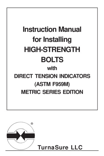
SECTION 2 – OPERATING INSTRUCTIONSSegmentNumber1234SegmentTypeRamp TimeDwellRamp TimeEndValue,Lbf/10154800RsetTime, min0.50.53.00 or 12.002-3CommentThis is used to load the sample.API Spec 10A Ramp rates of 16,000Lbf/min or 4,000 Lbf/min.Ends the program once the setpoint isreached.Configuring the DisplayScrollPageThe display indicates the sample load in units of Pounds-Force (Lbf ) and stores themaximum value. The display may be configured for other units of force by rescaling thedisplay and controller. Contact Chandler Engineering for instructions if the display must berescaled.Note that the value displayed by the controller must be multiplied by 10 to obtain Lbf. Thedisplay indicates in units of Lbf directly.The display provides the peak value to the 5270 Data Acquisition software every 1 secondusing the serial communication port.Note: The scaled peak value is available at Modbus register 133 (2:133f). To resetthe peak value, 5270 must be configured to transmit a 0 to Modbus register133 (2:133f) when a test is started. This is accomplished using the StartSequence option in the instrument Test Profile definition. The device addressand register (2:133f) must be configured in the Advanced option for the Lbfload signal.Note: The display calibration is based on the calibration certificate provided with theload cell and the excitation voltage ( 10Vdc). If the instrument must berecalibrated, an independent load cell must be loaded into the press and usedto validate the output of the load cell in the instrument. Any changes to the
2-4SECTION 2 – OPERATING INSTRUCTIONScalibration values must be configured in the display and controller (CONFIG– IP menus).The display is configured to display the current value. To display the peak value, press theUP or DOWN arrow, the peak value will display for 2 seconds then revert to the currentvalue.The load cell used in the instrument is rated for 0 – 50,000 Lbf. The load cell output is notexactly 0.000 mV due to the mass of the platen. The display is adjusted to display 0 Lbfusing the Offset option. This value is set by the factory but may require periodicadjustments: Press Scroll one time until OFS.1 is displayed.Press UP or DOWN arrow to change the value. Adjust the value until the main displayindicates 0 Lbf.Press Scroll two times to return to the main display.Although the 5270 software resets the peak value in the display when a new test starts, theuser may manually reset the stored peak using the following procedure: Press Scroll two times until RES.L is displayed.Press UP or DOWN arrow two times to select YES. The display will flash.Press Scroll one time to return to the main display.Operating Procedure1. Turn the system On.2. If required, push the cylinder control switch, located to the right of the power switch, tothe Down position to lower the platen. This will lower the platen to provide adequateclearance for the sample.3. Turn the cylinder control switch to the Off position.4. The platen has an engraved square that will approximately match the size of the sampleblock. Place the sample within the center of this square. It is critical that the sample becentered on the platen. Leave approximately ¼” of clearance between the sample and thetop platen.5. Close the door on the press assembly.6. Reset the peak value stored in the display by pressing the Scroll button until RES.L isdisplayed. Press Up or Down arrow two times to select YES. The display will flash.Press the Scroll button to return to the main display.Note: The 5270 DACS software will automatically reset the peak value stored by thedisplay when a data acquisition test is started.
SECTION 2 – OPERATING INSTRUCTIONS2-57. If using a data acquisition system, start the program.8. Confirm the controller is idle and in manual (MAN) mode by performing the steps below.a. Press and hold the RUN/HOLD button for three seconds or longer. This will resetand idle the controller. The RUN and HOLD indicators will extinguish.b. Press the AUTO/MAN button to switch from automatic (AUTO) mode to manual(MAN) mode. The MAN indicator will illuminate.9. Select the proper ramp time in segment three (Seg.n 3) of the controller program to matchthe rate desired. Additionally, select the target pounds-force value in segment three(Seg.n 3), if the desired value is different than 48000 Lbf. DO NOT change any othersegment values.To change the Seg.n 3 values;a.b.c.d.e.f.g.h.i.Press the Page button until the Prog menu appears.Press the Scroll button until the Segment number 3 is displayed (Seg.n 3).Press the Scroll button.Enter the segment type (tYPE). Use the Up/Down buttons to enter a ramp time(rmP.t) type.Press the Scroll button twice.Enter the target setpoint (tGt). This is the 48000 at 4800 of the ramp, expressed inunits of Lbf/10. (For example, 48000 Lbf 4800)Press the Scroll button to display duration parameter (dur).Enter the dur
The Chandler Engineering Model 4207D Digital Compressive Strength Tester is designed for operator safety. Any instrument that is capable of high pressures should always be operated . Door interlock switch: Prevents