Transcription
1Glorystar Install GuideHDVR12003.19.2021Glorystar requires that you carefully read through these pagesbefore beginning the installation.Please call Glorystar with any questions regarding your Glorystarequipment or installationThis guide is intended for an individual experienced in performing the varioustasks described, including: Determining an antenna location with a view of the satellites positions. Climbing a ladder and working on your roof. Observing safe working practices around heights and electrical hazards. Determining if water pipes, gas lines or wires are hidden before drilling. Using a power drill to drill holes into your house. Routing cable through walls, crawl spaces or attics. Safely lifting and securing the 25 lb. antenna assembly. Grounding the system as recommended in the National Electric Code.If you don’t feel completely comfortable with these tasks, you may considercontracting the installation with a local satellite technician.Web site http://www.FTAinstall.com provides a free referral service for localinstallers. Please visit today!www.glorystar.tvToll Free 866-597-0728
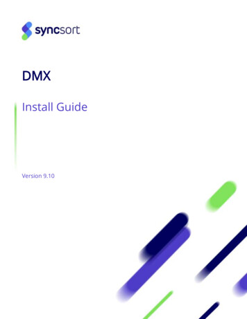
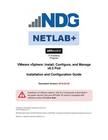
2Glorystar System Parts ListSatellite ReceiverInstallation KitTools RequiredSocket SetDrill and Bits90cm Dish / LNBFPhillips ScrewdriverHammerTape MeasureSite SurveyIf you feel comfortable with drilling holes in the wallsand/or roof of your home, climbing ladders, attachingwires to the ground according to NEC and local codesand following step-by-step instructions, you mightconsider installing your own system.The installation does require precise tuning and a greatdeal of patience to correctly install.Have you recently installed a light switch, ceiling fan,basketball hoop and programmed a VCR? If not, thisproject might not be a good time to hone your mechanicaland electrical skills!To simply a first-time install, do not use pre-wire or previously usedcoax cables and unknown switches. Do not attempt to use splitters forsimultaneous viewing on multiple receivers. Splitters typically do notsupport multiple satellite receivers.
3Where Is The Satellite?Before assembling any equipment it is important to verify that the installationlocation has a suitable area to safely and securely mount the satellite dish and havea clear line of site to receive the satellite signal. The satellite dish must be pointeddirectly at the satellite, with NO obstructions between the two. This means NOtrees and NO buildings. Satellite signals will not pass through leaves, limbs, soconsider future tree growth, house remodeling or additions and new constructionin your area. The dish cannot be installed indoors!In North America, the satellite dish will be pointed towards the South, Southeast orSouthwest. Satellites are located directly over the equator and are approximately23,000 miles away! Before you start, you will need to determine if it possible to“see” the satellite from your location.Satellite Compass (Azimuth) Reading:Please note: 97 Degrees West is not the compass reading! 97W is the assignedorbital slot which corresponds with the earth’s Longitude. The Galaxy 19 satelliteis just east of DirecTV’s main satellite at 101 Westwww.glorystar.tvToll Free 866-597-0728
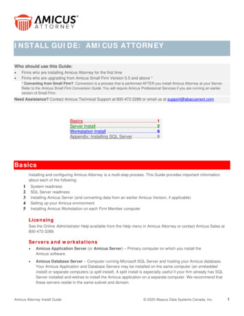
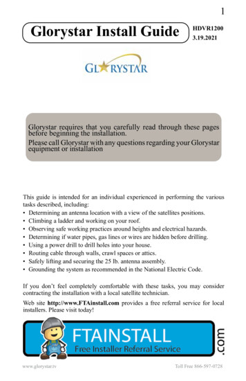
4How High Up in the Sky are the Satellites?Depending on where you live, most NorthAmerican satellites will be at an elevationangle between 30 and 60 degrees in NorthAmerica. Northern Canada and Hawaiianelevations can be as low as 10 degrees, butin Central American and the Caribbean, thedishes are often aimed almost straight upbetween 70 - 90 degrees!Satellite Dish Elevation Angle:Sight along the top edge of the elevationangle finder with the weighted stringregistering the correct elevation angle foryour target satellite. Is the line of sight clearwith no branches, limbs or tall buildings?Elevation Angle FinderIf you are mounting your dish on a motor,consult with the motor installation manualfor recommendations on dish placementand mounting.Be sure to perform a site survey to determine the best location to see as manysatellites as possible. The satellites are in an arc that begins at the easternhorizon reaching to the highest point directly south then extending to the westernhorizon.Where to Mount the Dish?Use the aiming coordinates included with this system or found at http://www.GeoSatFinder.com along with a compass and the Site Check Angle Finder foundon the last page of this manual to locate a suitable area for mounting the dish.While facing south, hold the compass levelin the palm of your hand. With the red needlepointed exactly at North, reference thecompass reading for your target satellite. Arethere any obvious obstructions? If the line ofsight appears clear, continue to the check theelevation angle.Compass
5Dish Mounting OptionsWe recommend ground mounting a fixedsatellite dish on a 1 5/8” heavy wallgalvanized post set in cement. Attach a boltor muffler clamp to the bottom of the post toprevent the post from twisting in the hardenedcement. These items are readily available atany hardware store. Filling the post with a wetcement mixture will provide greater rigidity.The post must be perfectly plumb, level on allsides. Posts standing higher than 7 feet shouldbe stabilized to prevent movement duringhigh winds. The post should be installed inadvance of the install as the cement can take24 - 48 hours to set. DO NOT install the dishon a wooden 4” x 4” post or on a tree. Thegrain of the wood will twist during dry andrainy seasons causing the dish to swing offof the satellite causing reduced or loss ofsignal. Take proper precautions to protect thedish from being bumped during yard care ordamaged by children at play.Wall MountGround Post MountRoof MountThe GEOSATpro 90cm dish assembly includes a heavy duty universal wall / roofpost mount. This mount can be attached at almost any angle and provides a stablesecure mount even in high wind regions if properly attached. The tripod legsMUST be installed. The universal post will fail under moderate wind load if thetripod legs have not been installed to support the larger wind load area of a 36”dish. The dish and mount are designed to remain operational in winds up to 80 mph and survive wind gusts over 110 mph.www.glorystar.tvToll Free 866-597-0728
6Dish AssemblyBefore assembling a metal dish it is Extremely Important to verify that thereflector was not warped or bent during shipping. Failure to check for dish warpingor damage could lead to many frustrating hours of trying to locate the satellite.This simple test may be the most important step in a successful installation!Bad - Warped ReflectorGood - ReflectorFind a perfectly flat surface such as a garage cement floor and lay the reflectorface down. Are the edges of the reflector laying perfectly flat? If any area of theedge is raised by even an 1/8th of an inch reception of the satellite signal will beaffected!If you cannot find a perfectly flat surface or if thedish is already installed, perform the string test.Tape a string horizontally from edge to edgeacross the center of the dish. Tape a second stringvertically from top to bottom on the edges of thedish.If the strings do not lightly touch in the center,the dish is warped and it must be corrected beforeaiming the dish.Fixing a Warped ReflectorTo correct a warped reflector, hold the dish likea steering wheel and quickly thrust the reflectoraway from your body like the motion of passinga basketball. This quick action will cause thereflector to slightly flex and spring back into thefactory pressed shape.Check for correction with the string test. It maybe necessary to repeat the flexing process severaltimes until the reflector edges are uniformly flat.
7GEOSATpro 90cm Dish HardwareItem QuantityDescriptionSize16Carriage Bolt1/4” x 1/2”234522131Phillips ScrewHex NutHex NutCarriage BoltM4 - 16mM41/4”1/4” x 1 1/4”678122Structural BoltElevator BoltWasher1/4” x 2 1/2”1/4” x 1 1/4”1/4”92Carriage Bolt1/4” x 3/4”101112ABC221411Phillips BoltHex NutPhillips BoltHex Flange BoltHex NutHex Tap Bolt1/4” x 1/2”1/4”1/4” x 1 1/4”1/4” x 1/2”1/4”1/4” x 3 1/2”D1Fastener InsertPlease contact your reseller if any of these parts are missing or damaged. Mostreplacement hardware items can be purchased at a local hardware supply store.Important Note:An assembled dish will not be accepted for refund.www.glorystar.tvToll Free 866-597-0728
8Attach the LNBF Arm to the Elevation Bracket.Assemble the Elevation Bracket and PostClamp. The Post Clamp has two holesdrilled. One hole is stamped with an A and the other with a B.Assemble the Elevation Bracket to thePost Clamp inserting Structural Bolt A(part #6) through the hole stamped A ifthe Dish Elevation Angle is between 10 60 degrees. Assemble using hole stampedB if the elevation angle is to be between50 – 90 degrees. Most installations inthe US and Canada will use ElevationScale A type assembly. Installations inMexico will usually use Elevation ScaleB assembly.The dish has been correctly assembledfor Measuring the Dish ElevationAngle using Scale A (10 - 60 degrees)if a letter B is visible stamped on thebottom of the Post Clamp.After verifying the Reflector is not warped,mount the Reflector to the ElevationBracket and install the two LNBF ArmSide Supports. The Side Arm Supports willperfectly center and support the LNBFs foroptimal reception.
9Universal Post Mount AssemblyMount the Universal Post Mount Foot Plate toa wall stud or roof rafter using two 5/16th x 3”lag bolts. Additional 5/16th x 2” lag bolts on theouter edges will increase stability. To preventwater leakage, use the included silicone sealantor other waterproofing product on all wall or roofpenetrations.The Universal Post Mount can be assembledfor flat and pitched roof or wall typeinstallations. The post has two slots forattaching to the Foot Plate on both ends of thetube. This allows the dish to be mounted inone of two methods. Either with the “J” at thebottom of the post providing a higher reach(as pictured), or the “J” is positioned at thetop of the post for greater outward reach.Level and Secure PostInsert the Bubble Spirit Level into the topof the post. Be sure that the level is seatedlevel and flush with the top edge of thepost.The unique slots in the post tubeallows the post to be leveled or madeplumb in almost any installationposition.If the post is not exactly plumb, theelevation scale will not be accurateand it will be very difficult to locatethe satellite and properly tune thedish for reliable reception.www.glorystar.tvToll Free 866-597-0728
10Center the bubble in the level then tightenthe 4 flange bolts to secure the post. It isvery important to make sure that the post isNot Level Levelperfectly plumb (level on all sides).The Most Critical step to providing astable mounting platform for the dish is theinstallation of the Tripod Support Legs. Ifthe lag bolts cannot be secured directly intoa stud or rafter, the legs should be securedinto plywood sheeting with either a backinga toggle bolt or to a 2 x 4” that is lag boltedbetween the rafters or studs.The legs are required to support the wind load on the universal postmount. Failure to install the tripod support legs will result in collapseof the post even during moderate winds. The post is not designed tosolely support the dish without the tripod support legs. If you hire alocal installer, be sure that the tripod support legs are installed.Place the assembled dish onto the top of the post with the StructuralBolt #6 sitting on top of the post. Loosely secure the mast clamphardware until the dish only moves when applying light pressure tothe rotate the reflector.LNBF Clamp AssemblyAssemble the single LNBFClamp and attach to theLNBF arm.
11LNBF InstallationThe LNBF catches the satellite signals reflected from the dish and send the signaldown the coax to the receiver. It is important to properly install the LNBF. Insertthe LNBF into the clamp with the cap facing the reflector then lightly tighten thetwo screws to secure the LNBF.Set the LNBF Rotation (Skew Angle) to thesetting specified in the aiming instructionsprovided with your system. The LNBF rotatesin the circular clamp until the centering linealigns with the LNBF Rotation angle. Failureto set the correct LNBF Rotation will resultin not finding the satellite!LNBF Rotation:When standing in front of the dish and lookingat the back of the LNBF and towards thereflector, rotate the LNBF counter clockwise(left) for a positive ( ) LNBF Rotation(Skew) setting and Clockwise (right) for anegative (-) LNBF Rotation (Skew) setting.Start with the LNBF slid back as far awayfrom the reflector as possible. Tighten thescrews to secure the LNBF from rotating. Noneed to overtighten and break the clamp.Dish AimingWhen setting the elevation angle on an offsetdish, it is important to note that the dish willappear be aimed lower than the actual elevationangle to the satellite. The scale on the elevationbracket is calibrated for accurate aiming whenthe post is installed perfectly plumb (leveled onall sides). The dish elevation angle is not set bythe angle of the LNBF arm or face of the dish.www.glorystar.tvToll Free 866-597-0728
12In North America, satellites are always located South of your location. Tocorrectly aim the dish you must first accurately determine the exact compassreading angle (azimuth). Metals, electricity and other magnetic disturbances cancause the compass to point incorrectly.Compass readings should be made at least 10 feet in front of or behind the metalsatellite dish and away from any large metal object such as metal buildings, airconditioners, vehicles, utility and power lines or electrical panels. Check compassreading several times to reduce install time and the need to hunt the entire southernsky for the satellite signal.Identify a reference point on the horizon like a tree, utility pole or other landmarkthat lines up with the compass reading. Installers often find it easier to align thedish if they can reference an object that has been identified with the compassreading. If you cannot locate a visual reference, stretch a 10 - 20 foot rope outin front of the dish in the direction of the compass reading pointing towards thesatellite.Move directly behind the dish and align the dish so that the LNBF arm is aimeddirectly at the reference landmark or in line with the rope. Semi-tighten the postclamp nuts, but allow the dish to be just loose enough to be rotated left or right byapplying light pressure.
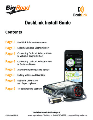
13HDVR1200 Satellite ReceiverThe Front panel of the HDVR1200 satellite receiver has many of the importantcontrols needed for operation of your Glorystar system. It is important to installthe receiver so the front display can be visible for proper remote control operationand to have easy access to the control keys in case the remote control is misplaced.Rear Panel1. Connect USB 2.0 Devices for DVR / Media / Upgrades / WiFi (5v/500ma)2. Connect Analog Component Video to TV or other video equipment3. RS232 Null Modem Serial Port for Upgrade and Diagnostic4. Connect to the Satellite Dish Coax Cable5. Loop Satellite Signal Out (not recommended for 2nd receiver connection)6. Connect Optical Digital Audio to Digital Audio Amplifier7. Connect Digital HDMI Video and Audio to TV or other video equipment8. Connect Analog Composite Video to TV or other video equipment9. Connect Analog Audio Left/Right (decoded Dolby) to TV or other equipment10. Connects to DC Power Supply (12vdc / 1500ma / positive tip)www.glorystar.tvToll Free 866-597-0728
141. LED display lights to verify remote operation2. Enter the Manual Timer Setting menu3. Display Media Player for Videos / Photos / Music4. Page Down in a List and DVR Scan Rewind5. Skip Rewind6. Play DVR / Media7. Freeze Video or Pause DVR / Media8. Display DVR Recordings List9. Display Satellite List10. Display the Main Menu Screens11. Change Channel or Menu Navigation Up / Down12. Display Channel Banner, 2x for Program EPG,3x for Service Information13. Display Electronic Program Guide (if provided)14. Increase / Decrease Volume15. Numeric / Alpha Keys for direct Channel Changeand Menu Setting16. Mute or Enable Muted Audio17. Select Standby or Operation Mode18. Select Closed Caption ON / OFF19. Display a Full Screen Signal Meter20. Page Up in a List and DVR Scan Forward21. Skip Forward22. Stop DVR Play or Record / Stop Media Playback23. Start DVR Manual Record24. Select the Favorite List Mode25. Magnify a Portion of the Screen26. Exit Screens or Functions27. Display the Channel List or Accept a Menu Item28. Increase / Decrease Volume or Menu Navigation Left / Right29. Return to Previous Channel30. Change Channel Up / Down31. Select Alternative Language / Audio Mode / Sound Track32. Select to View TV or Listen to Radio ChannelsRemote Shortcuts Turn the Receiver ON / OFF - 17Change Channels - 11 or 30Adjust Volume - 14 or 28Mute Audio - 16View TV / Listen to Radio - 32 View Channel List - 27View Channel Banner - 12View Signal Meter - 19Electronic Program Guide - 13(if available from the broadcaster)
15Connect Receiver to a TVCAUTION: DO NOT ATTEMPT TO OPERATE ELECTRONICDEVICES IN AN UNSAFE LOCATION OR IN VIOLATIONOF SAFEGUARDS PROVIDED IN THIS MANUAL OR ANYOTHER EQUIPMENT MANUAL PROVIDED WITH THISSATELLITE SYSTEM.Remove the satellite receiver and remote control from the packaging. Inspect theunit before operation. If any equipment is damaged or if you have any questions,please immediately contact your reseller. Install the two included AAA batteriesinto the remote control battery compartment.The BEST and Easiest method to aim the satellite dish is to temporarily placethe satellite receiver and a small TV near the satellite dish. This method allowsthe installer to see the signal changes that occur with small dish movements. It isextremely difficult to install the satellite system if the TV is inside the home andout of the view of the installer. Attempting to communicate the signal readingswith a second person viewing the TV will complicate the aiming process!Best Quality PictureStandard Quality PictureTo view high definition video in HD and listen to digital audio, connect a HDMIcable between the receiver and TV. No other cables are needed with the HDMIcable.A basic connection for standard definition SD TV viewing is to connect the to theTV with the included RCA cable. Connect the yellow Video port and the white/red Audio RCA jacks from the receiver to the yellow/white/red RCA plugs on theTV’s AV IN jacks.Plug the television power plug into a surge protected AC power strip. Turn theTV power ON and set the TV to the AV input. The TV is now ready to view thesatellite receiver.www.glorystar.tvToll Free 866-597-0728
16Connect a short RG6 coax cable from the LNBF on the satellitedish to the SAT IN port on the rear panel of the HDVR1200.Plug the satellite receiver’s power supply into the 12VDCport on the rear panel of the HDVR1200. Plug the HDVR1200power supply AC plug into the surge protected power strip.Standard Definition Connections (opt.)Older TV: Only Antenna JackVCR - Standard DefinitionConsult the owners manual provided with TV, VCR or other device that willbe connected to the GEOSATpro satellite receiver. Questions regarding theconnection to any other equipment should be directed to the manufacturer of thatdevice.
17Receiver Activation and Set-up1.When the receiver is first poweredON it will display “Welcome! Pleaseselect Install Type”. Press the OK keyon the remote control to install for theGlorystar Christian Satellite Service.2.Press the remote control Leftor Right Navigation key to select theconnection cable type used to connectthe satellite receiver to the TV. If aHDMI cable is connected, select HDMIthen press OK key and continue to step# 3. If a RCA cable is used, select RCAthen press OK key and skip to step # 53.TV Resolution - To display thebest picture quality, the HDMI outputneeds to be set to the highest qualitythat the TV supports. Pres
www.glorystar.tv Toll Free 866-597-0728 3 Before assembling any equipment it is important to verify that the installation location has a suitable area to safely and securely mount the satellite dish and have a clear line of site to receive the satellite si