Transcription
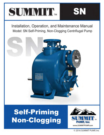
Submersible PumpMaintenance and RepairPresented by: Rick Alvarez
Why Perform Preventative Maintenance? What Does Preventative Maintenance Consist Of? What If My Pumps Need Repair? Summary Identification of Major ComponentsCost of PumpingPump and System CurvesBest Efficiency, POR, AOR ElectricalMechanicalChecklistMaintenance Report Difference between a repair and a complete overhaul Procedure for refurbishing a submersible pump
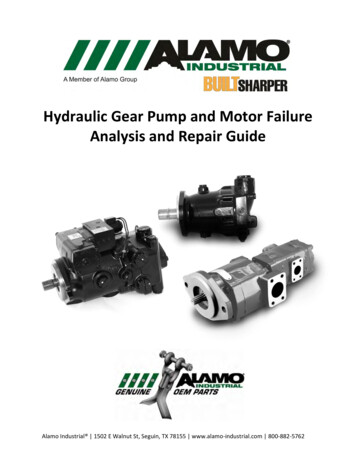
Cable Entry Terminal board Upper bearing Stator Seals Stator housing Rotor unit Lower bearingImpeller
Energy used to operate pumps Dependent on flow rate, total pressure and overallpump efficiency Labor and parts to maintain and repair pumpsCost will inevitably go up without preventativemaintenance! Efficiency decreases Catastrophic failure WILL happen!
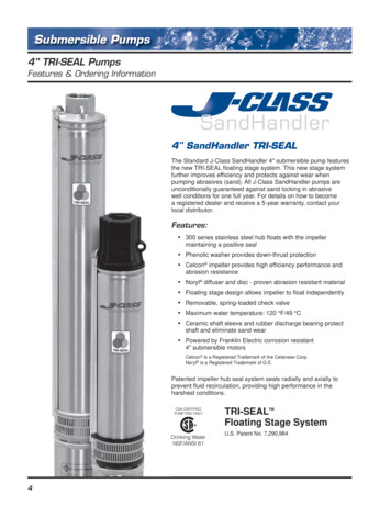
It is always best for the duty point to benear the pump’s best efficiency point (BEP)System curvePressure Head (FT) Duty point at BEPPump curve Preferred Operating Range 70-120% BEPEfficiencyFlow (GPM) Allowable Operating Range 50-125% BEP
IMPORTANT NOTES:Always follow proper safety procedures!!!Lockout/tagoutConfined SpaceAlways read and follow the instructions andsafety precautions in your O&M manual!
Electrical Control Panel Check and tighten all terminationsInspect and test control panel operationTest telemetry/alarmsRecord voltageIdentify and correct any issuesPump Amp readingsMotor winding resistanceMegger readingsOvertemp/leakage sensors
Running pump farright of BEP (runout,overloaded motor)Partial drag onimpeller (towels,wipes, rags, etc.)Blockage or clogImpeller clearancetoo tight Running pump farleft of BEP(deadhead)Closed dischargevalvePartially cloggedcheck valveAir in force main
Indicator of possible motorwinding problems All readings should be thesame
Less than 100megohmsunserviceable- repairrequired 500 megohms 1000 megohms 2K megohmsmoisture present/ insulationdegraded- repair should bescheduledserviceable, but showingsigns of degraded insulationnew condition
Stator Thermal SwitchesThree (3) Switches Wired In Series, Placed In The Stator End TurnsWhen The Stator Is Wound, With Two Leads Coming out of The Stator.
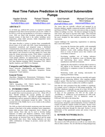
Flygt Leakage Sensor Reed contact in polyurethane filler Magnet Metal sheetprotectingagainst magnetfield Floating body Tape for fixing Aluminum profile
Flygt FLS Leak Detector The normal or safe condition resistancereading or values of the FLS The leak or fail condition resistance readingor values of the FLSunit is in the 1500 Ohms range. At this pointthe switch contacts are unit is in the 300 Ohms range. At this pointthe switch contacts are open. closed. Overheated motor or failed thermal sensorwill result in an open circuit
Overloaded Properly sizedbreakers/overloads UnbalancedVoltage Phase monitor Voltage Surge TVSS/voltagemonitor
Mechanical Change oil or coolant Inspect oil or coolant for evidence of sewage Minute amounts are normal and not usually a cause forconcern Inspect motor chamber for evidence of sewage Should be thoroughly inspected to determine where it’scoming from. Cable entry Failed seals Check Impeller Note any physical damage or excessive wear Adjust clearance to OEM specs (if adjustable) If not adjustable, pump may require new wear ring
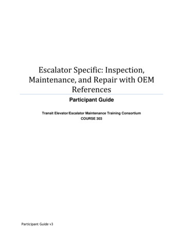
Oil ChamberAlways ReplaceThe “O” Ring Or“Dubo Washer”Never OverTighten TheSlowly RemoveInspect. PlugsThe Oil Inspect.Plugs As This IsA PressurizedSection Of ThePumpAlways Fill The Oil Housing To The RequiredCapacity According To The O&M Manual ForThe Pump You Are Working On.
Bearings Evidence of rubbing orwear Inadequate lubrication Improper handling Excessive hours VibrationSeals Two types of Failure - physical damage orseparated faces Operating outside AOR? Impeller worn and unbalanced? Cavitation or suction recirculation?
1.2.3.4.5.6.7.8.9.10.11.12.13.Check electrical condition of insulation on power cable(s) and on all phases of the motor (in Meg Ohms).Check for any loose or faulty electrical connections within the control panel.Measure resistance between stator windings (in Ohms).Check voltage supply between all phases of the electrical control panel.Check voltage balance between all phases on the load side of the pump / mixer control panel with pump / mixer running (VAC).Check amperage draw on all phases of the motor (in Amps).Check condition and operation of the motor thermal protection control system (if equipped).Removal of pump / mixer from the lift station for physical inspection.Check condition of upper and lower shaft seals (inspect condition of motor / stator housing, if applicable).Check condition and operation of leakage and bearing sensors (if equipped).Drain oil from oil housing and replace with new oil.Check for worn or loose impeller or propeller.Check impeller wear rings (rotating & stationary) – Note wear rings are a wear item and are not included in the cost of thiscontract.14. Adjust clearances as needed for optimal operation.15. Check for any unusual noise in the upper and lower bearings.16. Clean, reset and check operation of the level control system (if equipped).17. Check for physical damage of power and control cables.18. Check for correct shaft rotation.19. Reinstall the pump / mixer and check operation (if liquid level in the station permits).20. Test the pump / mixer operating cycle, under load (if liquid level in the station permits).21. Perform draw down test on pumps to establish GPM being produced (when possible).22. Perform shut off head test on pumps to establish pressure being produced (when possible).23. Check operation of valves and associated equipment.
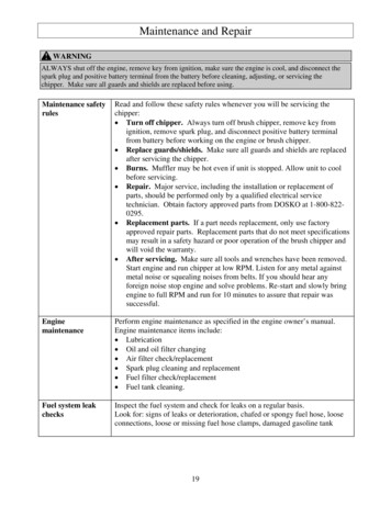
Technician willcomplete a maintenancereport Identifies any correctiveaction that may berequired. Ensures compliance withmanufacturer warrantyrequirements
Difference between a repair and an overhaul A repair simply replaces whatever component orcomponents failed. An overhaul begins with a complete inspection andrestores the machine back to OEM standards orbetter
Disassemble,clean, sandblastall componentsWrite completedisassemblyreport identify allcomponentsrequired torestore thepump to OEMspecs
Analyze motor Surge Test Megger Test Windingresistance Test Visualinspection Bake stator toremove anymoisture
All wear parts are replacedwith new SealsBearingsO-ringsImpeller/wear ring (ifrequired)Damaged components canbe restored by: Welding, coating, platingmachining, grinding, etc.
Rotating assembly isconstructed with allcomponents Total Indicator Runout is verifiedto .003” Certified balance to 4W/N Entire pump is assembled Pressure tested Test run for amp draw, phasebalance, vibration Painted and preserved forshipping
Optional procedures fordifficult applications: Ceramic coating on impellers Tungsten Carbide coating onimpellers, wear rings, volutes Chrome plating on shafts
Preventative maintenance Extends the life of yourpumps Sustains the efficiency of yourpumps Identifies potential problemsbefore the point ofcatastrophic failure Protects your investment
Repair Make sure the shop youchoose has all the necessarytools, procedures andqualifications A properly refurbished pumpwill perform as new andprovide many more years oftrouble-free operation
Perform draw down test on pumps to establish GPM being produced (when possible). 22. Perform shut off head test on pumps to establish pressure being produced (when possible). 23. Check operation of valves and associated