Transcription
Impression RailExpressFull Glass RailingInstallation GuideAluminum Posts . 4Glass Panels . 8See Railing Panel Installation Guidefor Stair Panels and Gate Kits.TimberTech.com
Installing Impression Rail ExpressGlass Railing SystemImportant Information Please read all instructions completely before starting any part of the installation. Always make sure to visit www.TimberTech.com toensure you are viewing the most current installation instructions, care and cleaning, technical information and more. Impression Rail Express should be installed using the same good building principles used to install wood, composite, or metal railing andin accordance with the local building codes and the installation guidelines included below. The AZEK Co. LLC accepts no liability or responsibility for the improper installation of this product. Impression Rail Express may not be suitable for every application and it is the sole responsibility of the installer to be sure that ImpressionRail is fit for the intended use. Since all installations are unique, it is also the installer’s responsibility to determine specific requirements inregards to each rail application. The AZEK Co. LLC recommends that all applications be reviewed by a licensed architect, engineer or local building official beforeinstallation. If you have any questions or need further assistance, please call AZEK Customer Service at 877-ASK-AZEK (877-275-2935),or visit our website at www.TimberTech.com. Impression Rail Express is tested as a whole system and should be used that way. It is not intended to be used in conjunction with otherrailing systems or fasteners. The following Installation Guidelines are applicable for installation of Impression Rail Express only. IMPORTANT: Make sure the DRIVE TOOL/DRILL is configured or set to use the SCREW setting when driving and/or tightening allFASTENERS. SAFETY: Always wear goggles when handling, cutting, drilling and fastening materials. Failure to install this product in accordance with applicable building codes and Impression Rail Express’s written Rail Install Guide maylead to personal injury, affect rail system performance and void the product warranty. The buildup or generation of static electricity is a naturally occurring phenomenon in many plastic based products such as carpeting,upholstery, and clothing, and can occur on alternative decking under certain environmental conditions. This static electricity can dischargeonce contact is made with hardware, railing, or other conductors of electricity.NOTE: IF INSTALLING POST LIGHTING,WIRING MUST BE INSTALLED PRIOR TOSECURING POSTS TO DECK/STAIR SURFACEAND INSTALLING TOP RAIL SNAPS.It is the responsibility of the installer tomeet all local code requirements and obtainall required building permits. The installershould determine and implement appropriateinstallation techniques for each installationsituation. AZEK Co. LLC or its reseller shallnot be held responsible for improper orunsafe installations.Page 2
Installing Impression Rail ExpressGlass Railing System* CAUTION *45 CORNERSPOST MUSTBI-SECT CORNER& USE 22.5 KITSuggested Tools:Important Note:Prior to construction, check with your local regulatoryagency for special code requirements in your area.Common railing height is 36" or 42". Post spans will vary dependingon job site conditions. Never span more than 6' on-center betweenrailing posts. Spans longer than 12' in length will require reducedpost spans. Refer to the system evaluation at the end of theseinstructions. For all other applications, consult a design professionalor an AZEK railing representative for more information. Readinstructions completely to get an understanding of how the productgoes together and how each piece affects the other. Appropriate fastenersfor mounting posts todeck Miter saw with carbidetipped non-ferrousblade Cordless drill Tape measure Level Power cords, dropsheets and safetyglasses 3/16" Drill bit 6" #2 Square drive bit Installation jig (optional)Important Note: 6' Panel Actual Length is 69.43" 3" posts are required to reach 6' length Only 3" posts can be used for glass infillPage 3
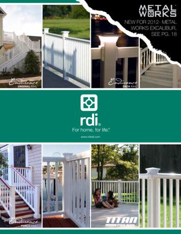
Installing Impression Rail ExpressGlass Railing Posts1Determine PostConfigurationsand Locations(end, center,corner, etc.)(Dia. #1)Dia. #1TOP VIEW2Prepare PostsPost preparation (Option 1 - No Install Jig) Measure 2-3/8" from end of post extrusionand place a pencil mark for location of bottomedge of glass receiver.3" SQ.POST Position bottom edge of glass receiver onpencil mark at 2 3/8", center receiver on postand secure with 2-#10 x 1-1/2" self-drillingscrews. (Dia. #2)Dia. #3RestInstallation Jigon Base Plate– Arrow Down Once bottom receiver is secure, measure29 3/4" for 36" rail height or 35 3/4" for 42"rail height from top edge of bottom glassreceiver, mark a line for placement of top clip.Place Clip inhole, hold clipfirmly whileinstalling (2)self-drillingscrews. Place rail clip bottom edge on pencil markand center clip on post, secure with baseattachment screws.Post preparation (Option 2 - With Install Jig) Install lower receiver to appropriate post face using Jig. (Dia. #3)LINE MARKPage 4TAPEMEASURE29 1/2”TOPRAILCLIP29 3/4" for36" Height.Finished GlassSize: 30 1/2"35 3/4" for42" Height.Finished GlassSize: 36 1/2" Measure 29 3/4" for 36" rail height or 35 3/4" for42" rail height from the top edge of the lower receiver (Dia. #2) and place apencil mark for placement of bottom edge of upper clip. Place rail clip bottom edge on pencil mark and center clip on post, securewith 2-#8x3/4" self-drilling screws. (Dia. #2)Dia. #22-3/8”BOTTOMGLASSRECEIVERLINE MARK
Installing Impression Rail ExpressGlass Railing Posts3Install Stair End Posts (if applicable) Temporarily install end stair post so rail centerlinealigns with top stair posts installed in Step 1(if applicable). Recommended post installationlocations are shown. (Dia. #4) Confirm with localcode officials before installing stair rail sectionsor stair rail posts to ensure compliance with localcode requirements.Important Note:DECKSURFACESTAIR DOWN3"3" TOPSTAIR POST3"3BSee Aluminum Railing Guideonline for complete stair railinginstallation instructions.3" TYPICALDia. #44BUILDING WALLInstall End Posts(if applicable)Install posts at all end locations withmaximum gap between post and wallto be less than a 4" opening. (Dia. #5)TEMPORARILY INSTALL3" BOTTOM STAIREND POST ALIGNEDWITH TOP STAIR ENDPOST (REFER TO STAIRINSTRUCTIONS)LESS THAN 4"OPENINGDECKEDGEDia. #53" CENTERLINETYPICAL5Install 90-degree CornerPostsPosition post on same 3" centerline(typical) and temporarily fasten usinga single fastener through base platemounting hole. (Dia. #6)TOP VIEWDECKEDGELOCATE ENDPOST3" CENTERLINETYPICALLOCATE90 CORNERPOSTDia. #63" CENTERLINETYPICALPage 5
Installing Impression Rail ExpressGlass Railing Posts6Install 45-degree CornerPostsPosition post on same 3" centerline(typical) and temporarily fasten to decksurface. Use one 22.5 Panel AttachKit (purchased separately) to install 45degree corner posts. (Dia. #7)TOP VIEW3" CENTERLINETYPICALLOCATE 45 ANGLED POSTDia. #7POST DISSECTSDECK ANGLETYPICAL3" CENTERLINETYPICAL7DECKEDGEDetermine Center Post LocationsLoosely lay center post over deck edge and adjust as requiredto determine final center post mounting locations. (Dia. 8 & 9)Dia. #8PLAN VIEWDia. #9CENTER LINEImportant Note:CLOSE UPVIEW 6' Panel Actual Length is 69.43" 3" posts are required to reach 6' length Only 3" posts can be used for glass infillPage 6
Installing Impression Rail ExpressGlass Railing Posts8Secure 3" Center Posts to Deck Install 3" posts centered between 3" end and corner posts.NOTE: 3" center posts must be installed with center screw chasesin-line with panel.Page 7
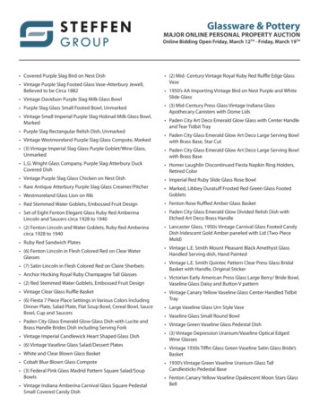
Installing Impression Rail ExpressGlass Railing Panels1Prepare Glass Channels Measure and cut top and bottom railextrusions to fit between posts (1/16" lessthan opening size).(Dia. #1)Note: Bottom vinyl rail channel should becut with bottom rail extrusion, top vinyl railchannel should be removed before cutting.(Dia. #2) Snap bottom foot block into bottom railassembly so mounting hole faces inwardto deck surface. (Dia. #2)BOTTOMVINYL GLASSCHANNELINSERT GLASS FOOT BLOCKINTO BOTTOM RAIL ASSEMBLYSO MOUNTING HOLE FACESINWARD TO DECK SURFACE.CUT TOP AND BOTTOM RAIL EXTRUSIONS1/16" LESS THAN OPENING SIZEDia. #2Dia. #1Page 8
Installing Impression Rail ExpressGlass Railing Panels2Install Top and Bottom Glass Extrusions Starting at end post or top stair post (Dia. #3A), install the bottom railextrusion, with vinyl insert, into the bottom receiver of the first two posts.Next, slide the top rail glass extrusion, without the vinyl installed, onto theupper rail attachment clips. Secure the posts to deck surface, then secure top rail glass extrusion to toprailing attachment clip (Dia. #3B & #3C). Continue working from one post tothe next. Install next piece of bottom rail, then secure the top rail extrusionto the rail clips until all rail sections are fastened to posts and posts aresecured to deck surface.NOTE: See Aluminum RailingGuide online for completepost installation instructions. Center foot blocks between postsand fasten to deck. (Dia. #13D)Note: Foot Blocks are requiredfor all spans of 4' or greater.TOP ANDBOTTOM RAILASSEMBLYTOPVIEWATTACHRAIL CLIPTO POSTUSING 2X#8 SELFDRILLINGSCREWSDia. #3AINSTALL 4X #8 SELF-DRILLINGSCREWS – 2 INSIDE, 2 OUTSIDECENTERFOOT BLOCKDia. #3BDia. #3CPage 9Dia. #3D
Installing Impression Rail ExpressGlass Railing PanelsImportant Note:The top snap covers should snap firmly onto the aluminum railing channels. Do not use a hammer. The top rails willsnap by applying pressure from one end to the other. If you’re having issues snapping on the covers, check the clipsto ensure that they are bottomed out into the aluminum railing channels. Foot Blocks must be installed BEFOREinstalling Top Rail Snaps.3Install Top Rail SnapMeasure between each secured postand cut top rail snap 1/16" less thanopening size (Dia. #4). Clean cut areasand apply touch-up paint on all exposedmetal. Snap each top rail snap over thecorresponding glass rail extrusion untilproperly seated.MEASURE, MARK & CUTNOTE: Do not install top snaps yet iflighting wires will be run through toprails.Dia. #4TIP: Roll the Top Rail Snap in placeto avoid scratching the posts and putweight down to get to the “second” snap.4TOUCH UPPAINT ONCUT ENDSAFTER CUTTING TOP RAIL SNAP AND PAINTING, PUSHSNAP DOWN BY HAND UNTIL PROPERLY SEATED.DO NOT USE A HAMMER!Install Top Glass Inserts Measure between posts and subtract2" from overall measurement. Cuttop vinyl glass channel to provideclearance at post clip locations.TOP RAILTOP INNERCHANNELGLASSIINSERT1" Insert glass channel into top railextrusion, butted against support clipapproximately 1" from post. (Dia. #5)BUTT TOP VINYLGLASS CHANNELAGAINST SUPPORTCLIP APPROX. 1"FROM POSTDia. #5BOTTOMVINYL GLASSCHANNEL3" SQ. POSTASSEMBLYBOTTOMRAIL ASSEMBLYPage 101/4" TEMPEREDGLASS PANEL
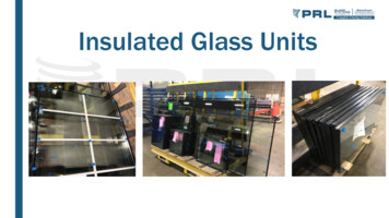
Installing Impression Rail ExpressGlass Railing Panels5Install Glass PanelsPosition glass so gap between paneledge and post is equal on both ends.Glass gap at ends is typically 3" butcan vary depending on application.Maximum gap must be less than 4".Insert glass panels upward into glassinsert (Dia. #6A) and swing panel overopening in bottom rail glass insert. Pullpanel downward until panel is restingfirmly inside of bottom glass insert(Dia. #6B). Continue until all glasspanels are installed.TIP: Window cleaner may help easeglass panel into top and bottom railassemblies.UPPER RAILEXTRUSIONTOP VINYLGLASSCHANNELGLASSPANELDia. #6ADia.#6ADia.#6BBOTTOMVINYL GLASSCHANNELLOWER RAILEXTRUSIONDia. #6B6Final InspectionWhen railing is completely installed, complete one finalcheck to ensure all fasteners are properly secured.Important Note:The diagrams and instructions in this brochure are for illustration purposes only and are not meant to replace a licensedprofessional. Any construction or use of the product must be in accordance with all local zoning and/or building codes. Theconsumer assumes all risks and liability associated with the construction or use of this product. The consumer or contractorshould take all necessary steps to ensure the safety of everyone involved in the project, including, but not limited to, wearing theappropriate safety equipment. Except as contained in the written limited warranty, AZEK does not provide any other warranty,either express or implied, and shall not be liable for any damages, including consequential damages.Page 11
AZEK Building Products1330 W Fulton Market, Suite #350Chicago, IL 60607 2019 AZEK Building Products. All Rights Reserved.TimberTech.com
Common railing height is 36" or 42". Post spans will vary depending on job site conditions. Never span more than 6' on-center between railing posts. Spans longer than 12' in length will require reduced post spans. Refer to the system evaluation at the end of these instructions. For all other applications, consult a design professional