Transcription
Hydraulic Gear Pump and Motor FailureAnalysis and Repair GuideAlamo Industrial 1502 E Walnut St, Seguin, TX 78155 www.alamo-industrial.com 800-882-5762
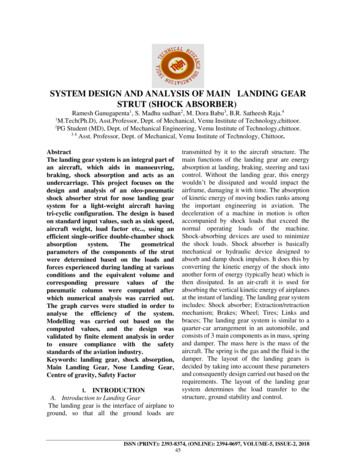
Hydraulic Gear Pump and Motor FailureAnalysis and Repair GuideThe heart of a hydraulic system is the hydraulic pump. The pump is the component thatreceives the mechanical energy supplied by the tractor or engine, and converts it to fluidenergy with the use of the hydraulic oil.A healthy pump will allow the mower system to perform at its maximum level of effectiveness.Properly maintaining the hydraulic system by changing the oil and the filters and by preventingor repairing leaks will provide hundreds of hours of trouble free operation.The fixed displacement gear pumps utilized by Alamo Industrial are of a proven design and willeasily provide exceptional service for the life of the machine. Failures of the front pump are, infact, limited to just a few specific modes such as overheating, over-pressurization, shaft failures,contamination and cavitation. In most cases, damage to the front pump is a RESULT of afailure and not the true cause of the failure. Simply replacing the pump without understandingWHY it failed will only result in additional failures and additional expense.Proper failure analysis of the front pump is essential to understanding why the pump failed, andthus determining the true cause of the failure. Knowing the TRUE cause of the failure willprevent additional failures.Hydraulic Gear Pump and Motor Failure Analysis and Repair GuideAlamo Industrial 1502 E Walnut St, Seguin, TX 78155 www.alamo-industrial.com 800-882-5762Page 2 of 3292016GS
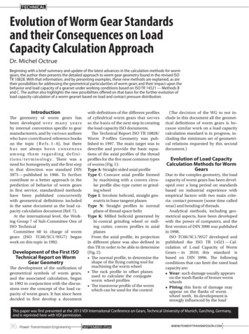
Thrust PlatesShaft End CoverLip SealPort End CoverMounting FlangeShaft BushingsDrive SplineDrive GearIdler GearInlet PortBearingGear HousingRing Seal (HighPressure)The front mounted gear pump utilizes power from the engine crankshaft to provide rotation ofthe pump. A flow of oil is produced by the pump due to this rotation. The amount of flow isdependent upon the size of the gears in the pump and the speed of the engine. Likewise, asthe pump is rated to produce the optimum flow at the rated speed, usually 1800 to 2000rpm,the pump is described as a Fixed Displacement Pump.(Single Pump shown above, Tandem Pump shown below)Bearing CarrierBushingsPumpingsectionsHydraulic Gear Pump and Motor Failure Analysis and Repair GuideAlamo Industrial 1502 E Walnut St, Seguin, TX 78155 www.alamo-industrial.com 800-882-5762Page 3 of 3292016GS
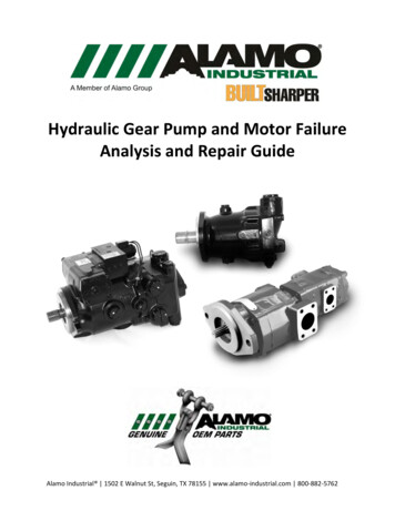
Tandem Gear Pumps may be needed when there are multiple functions that require differentflows such as a requirement where tractor hydraulics for boom movement is not available.Tandem pumps operate the same as single pumps, and incorporate a bearing carrier with adriven shaft coupler to provide the operation of both pumps simultaneously.Gear pumps and motorsemploy a pressure balancedthrust plate design. Oilpressure hydraulicallybalances the thrust platesand squeezes them againstthe two gear faces. Thesqueeze provides a sealbetween the gear face andthe thrust plate surface,preventing high pressure oilfrom slipping back to the lowpressure side of the pump.Mechanical seals and oilchannel inserts are usedto control the oil andblock it from leakingbetween the plate andadjoining castings.Hydraulic Gear Pump and Motor Failure Analysis and Repair GuideAlamo Industrial 1502 E Walnut St, Seguin, TX 78155 www.alamo-industrial.com 800-882-5762Page 4 of 3292016GS
A cross sectional view of the pumping chambers illustrates the flow path of the hydraulic oilthrough the gear pump. As the gears counter-rotate, the separating gear teeth create avacuum, drawing oil into the inlet. Oil is picked up by each tooth and carried around theoutside of the gear. Oil is NOT drawn through the center. The pockets between the gear teethand the housing are referred to as Pumping Chambers. As the gear teeth mesh on the outletside, oil is forced out of the pockets and exits the pump.The rotating action of the pump, therefore, results in a FLOW of hydraulic oil from the pumpwhich is dependent on the size of the gear teeth and the rotational speed of the pump shaft.Resistance downstream due to hose size, adapter fittings, elbows and system valves will restrictthe flow from the pump, thus resulting in pressure. High pressure on the outlet side of thehousing forces the gears to deflect into the low pressure (inlet) side. The gear tips or teethcontact the housing, preventing high pressure output oil from leaking back to the low pressureside.This contact between the gear teeth and the pump housing results in wear on the pumphousing and will produce cast iron contamination into the hydraulic system, especially with newunits. This inherent wear is normal and is expected but requires adherence to the maintenanceschedule, especially in regard to oil and filter changes after the initial break in period.Following the break in period, housing wear due to loading of the gears will diminish and willresult in a steady state which can be maintained for an extended period. Introduction ofcontaminants into the system or over-pressurization of the pump, however, will result inexcessive wear and eventually allow oil to leak back to the low pressure side of the pump.Hydraulic Gear Pump and Motor Failure Analysis and Repair GuideAlamo Industrial 1502 E Walnut St, Seguin, TX 78155 www.alamo-industrial.com 800-882-5762Page 5 of 3292016GS
Hydraulic Gear Pump and Motor Failure Analysis and Repair GuideAlamo Industrial 1502 E Walnut St, Seguin, TX 78155 www.alamo-industrial.com 800-882-5762Page 6 of 3292016GS
Pump and Motor Repair Procedures: DisassemblySTEP 1STEP 2Place the pump in a vise with the drive shaftpointing down. Clamp unit on the sides ofthe mounting flange. Do not clamp on thepilot diameter as it may damage the seatingsurface.Mark each casting in the assembly withmachinist’s ink or a prick punch to orient thecastings so unit can be reassembled later inthe proper position.STEP 3STEP 4.1Loosen and remove the four cap screws andwashers with a socket and wrench.Remove the port end cover subassemblyusing steps 4.1 through 4.3:4.1 Place the point of a large screw driver or achisel on the parting line between the portend cover casting and the gear housingcasting. Gently tap to separate the casingsand port end.Hydraulic Gear Pump and Motor Failure Analysis and Repair GuideAlamo Industrial 1502 E Walnut St, Seguin, TX 78155 www.alamo-industrial.com 800-882-5762Page 7 of 3292016GS
STEP 4.2STEP 4.34.2 Place two large flat bladed screwdriversinto the separation notches and pry up theport end cover until loose.4.3 Lift off the port end coversubassembly.STEP 5.1STEP 5.2Remove the gear housing subassembly usingsteps 5.1 through 5.3:5.2 Lift off the gear housing subassembly.5.1 Place the two large flat bladedscrewdrivers into the separation notches andpry up the gear housing until loose.Hydraulic Gear Pump and Motor Failure Analysis and Repair GuideAlamo Industrial 1502 E Walnut St, Seguin, TX 78155 www.alamo-industrial.com 800-882-5762Page 8 of 3292016GS
STEP 5.3STEP 65.3 Remove the thrust plate from thehousing. It may be necessary to gently tapthe thrust plate with the handle of ahammer or screw driver. Be careful not tobend or score the thrust plate. Remove anddiscard the small rubber pocket seals fromthe thrust plate.Remove and discard the rubber sectionseals from the top and the bottom gearhousing faces.STEP 7STEP 8Wipe the gear face surface dry with a cleanlint free cloth. Mark the teeth of the gear setat their mesh point with machinist’s ink orquick dry marker. This is to index the gearset for proper orientation duringreassembly.Remove the idler gear and the gear shaft.Keep them together as they are a matchedset. Handle with care to avoid damage tothe journals, faces, and teeth.Hydraulic Gear Pump and Motor Failure Analysis and Repair GuideAlamo Industrial 1502 E Walnut St, Seguin, TX 78155 www.alamo-industrial.com 800-882-5762Page 9 of 3292016GS
STEP 9STEP 10Gently lift off the thrust plate. Be carefulnot to bend or score the plate and matingsurface of the casting. Remove and discardthe rubber pocket seals from the back ofthe thrust plate. NOTE: Pay attention tothe orientation of the oil seal and channelon the bottom of the thrust plate.Inspect the bushings for wear. Replacefollowing the next steps if required.STEP 11STEP 12Use a bearing puller to remove thebushings.Use a large screw driver or a Check Tool toremove the check valves.Note: This step is optional depending onthe condition of the bushings.Hydraulic Gear Pump and Motor Failure Analysis and Repair GuideAlamo Industrial 1502 E Walnut St, Seguin, TX 78155 www.alamo-industrial.com 800-882-5762Page 10 of 3292016GS
STEP 9STEP 10Inspect all the components for wear andreplace as required.Remove the channel seals and discard.Hydraulic Gear Pump and Motor Failure Analysis and Repair GuideAlamo Industrial 1502 E Walnut St, Seguin, TX 78155 www.alamo-industrial.com 800-882-5762Page 11 of 3292016GS
Failure AnalysisLarge Particle ContaminationParticles too large to fit between the tight component tolerances of the gear pump or motorwill cause surface to surface contact removing material from the softer thrust plate. Damage tothe thrust plate surface, which provides a sealing surface between the high and low pressureoil, leads to leaks and a loss of performance. Additionally, continued wear due to theintroduction of large contaminants results in additional contaminants, which perpetuates theoverall problem.The pump thrust plate is one of the best placesto look for evidence contributing to the pumpfailure. Score marks on the plate in the photoindicate a “trail” of contaminants which weredragged across the surface of the plate.New components provide a smooth, even surface allowing a continuous oil film to existbetween the thrust plate and gear face. When these surfaces become scored the oil filmdissipates into the grooves interrupting the film. Metal to metal contact occurs, resulting in anincrease in friction and heat. The grooved plate surface can also provide an escape route forhigh pressure oil to go back to the low pressure inlet, resulting in a loss of pumping efficiency.Large contaminants lodged in thespaces between the gear teeth will result inscoring of the pump housing.Hydraulic Gear Pump and Motor Failure Analysis and Repair GuideAlamo Industrial 1502 E Walnut St, Seguin, TX 78155 www.alamo-industrial.com 800-882-5762Page 12 of 3292016GS
Large particle contamination may also result indamage to the gear teeth.Small Particle ContaminationMicroscopic particles the size of airborne dust can accumulate in the tiny tolerances of thehydraulic system. These particles can form a wedge between moving parts, increasing frictionand accelerating wear. The velocity of the tiny particles striking the wear surfaces can erodematerial, weakening the wear surface and causing spalling. This erosion of metal leads tointernal leaks in critical components and adds additional contamination to the hydraulicsystem. This wear reduces the system efficiency and affects pump or motor performance.Smaller contamination particles will beevident on the thrust plate in the formof small score lines, and is most evidentat the pressure point of the gear mesh.Hydraulic Gear Pump and Motor Failure Analysis and Repair GuideAlamo Industrial 1502 E Walnut St, Seguin, TX 78155 www.alamo-industrial.com 800-882-5762Page 13 of 3292016GS
Contamination wear will also be presenton the bushing surface of the pumpdrive shaft.Small contaminants will produce minorscoring of the shaft. Large particles mayproduce severe wear and galling of theshaft surfaceHydraulic Gear Pump and Motor Failure Analysis and Repair GuideAlamo Industrial 1502 E Walnut St, Seguin, TX 78155 www.alamo-industrial.com 800-882-5762Page 14 of 3292016GS
CavitationExcessive noise in a hydraulic system can be caused by the presence of air in the hydraulic oil.Introduction of air into the system can be the result of a leak in the suction line, air bubblesentrained in the oil, or insufficient pump or motor inlet flow which results in a vacuum. Thepartial vacuum vaporizes some of the oil causing air and or water to come out of solution.As the bubbles, created by cavitation and aeration, are carried around to the pump outlet, theincrease in pressure squeezes the bubbles. Implosions occur when the pressure becomes toogreat and the bubbles collapse inward.Air bubbles under pressure will implode and produce intense shock waves which bombard thesurface of the thrust plates. This process erodes the plates’ surfaces on the high pressure side.This erosion reduces pump efficiency and results in increased wear due to loss of the hydraulicfilm which normally protects from metal to metal contact.Cavitation is shown onthe thrust plate on thepressure outlet side ofthe pump in the formof pitting in the thrustplate surface.Discoloration of thisthrust plate may alsoindicate that excessiveheat due to lack of oilsupply was alsopresent.Hydraulic Gear Pump and Motor Failure Analysis and Repair GuideAlamo Industrial 1502 E Walnut St, Seguin, TX 78155 www.alamo-industrial.com 800-882-5762Page 15 of 3292016GS
Excessive System PressurePressure and hydraulic shock are also causes of pump failure. Pumps operating under acontinuous load at high pressure and for extended periods are susceptible to premature wearand failure. In addition normal operation of tree cutting or heavy brush cutting can causesudden pressure spikes which may act on the system too fast for the pressure relief valves torespond and protect the system from damage.Forces generated by the pump outlet pressure and gear area causes a deflection of the gears.This stresses the bushings that support the gear journals. The oil film needed to lubricate andcushion the pump elements becomes thinner
Hydraulic Gear Pump and Motor Failure Analysis and Repair Guide Page 8 of 32 Alamo Industrial 1502 E Walnut St, Seguin, TX 78155 www.alamo-industrial.com 800-882-5762 92016GS STEP 4.2 STEP 4.3 4.2 Place two large flat bladed screwdrivers into the separation notches and pry up the port end cover until loose.