Transcription
Repair and MaintenanceWelding HandbookSecond EditionXA00086820
Selection and Application GuideEsab Repair & Maintenance Consumables1
ContentsPage34ForewordAbbreviationsGouging – Cutting – PiercingPreheating and interpass temperaturesControlling weld metal dilutionThe use of buffer layers and build-up layersWelding 56810cast iron“difficult to weld steels”dissimilar metalsmanganese steelstool steels and steels for high-temperature applications1418222630Hard-facing3434373839 Wear factorsBase materialWelding processesTypes of hard-facing weld metalGuide to classification of consumables for hard-facingaccording to DIN 8555 ESAB hard-facing products Quick guide – selection of consumables404142Illustrated applicationsConsumables – product data for cast ironbuffer layers and build-up layers“difficult to weld steels”dissimilar metalsmanganese steelstool steels and steels for high temperature applicationshard-facingnon-ferrous metalsRecommended preheating temperaturesComparative hardness scalesBase metal identification guideApplication index – alphabetical orderProduct – 2234568990919191939598105Table 7 108Table 8 109Table 9 110112115
ForewordEvery day, welders throughout the world encounter the initials OK on the consumables they use. OK for Oscar Kjellberg, the founder of Esab AB. OscarKjellberg first invented a new welding technique and followed it up with thecovered electrode. These inventions are the origins of Esab.Oscar Kjellberg qualified as an engineer and worked for several years on acouple of Swedish steamships. It was during this period at the end of the1890s that he came across the problem for which there was no effective solutionat that time. The riveted joints on steam boilers often leaked. Attempts weremade to repair the leaking joints with nails which were forged to produce smallwedges which were then pushed into the joints. Simple electrical welding wasalready in use, but Oscar Kjellberg had seen electrical welding repairs and theresults were poor, as there were still cracks and pores.He realized, however, that the method could be developed and wassupported by the leading shipyards. Oscar Kjellberg set up a small experimentalworkshop in the harbour in Göteborg.In the shipyards of Göteborg, the method quickly attracted a great deal ofinterest. It was obvious that it could provide tremendous benefits when welding and repairing ships. Since then, this repair technique has been furtherdeveloped and implemented in other segments.Today, Esab can offer repair and maintenance consumables for most materials and welding processes.In this handbook, you will find Esab Repair & Maintenance products and anumber of applications in which these products are used. The products shownfor each application are general recommendations and should only be used asa guide.For further product information, please refer to the ESAB Welding Handbookor to your local Esab dealer.3
AbbreviationsRmRp 0.2AHRCHBHVawwh tensile strength yield strength elongation after rupture hardness HRC hardness Brinell hardness Vickers as-welded work-hardenedSMAWFCAWGMAWSAW shielded metal arc welding (manual metal arc welding) flux-cored arc welding gas metal arc welding submerged arc weldingDC DC –ACOCV direct current – reverse polarity direct current – straight polarity alternating current open circuit voltageChemical nVanadium
Gouging – Cutting – PiercingGeneralOK 21.03 is a specially-designed electrode for gouging, cutting and piercing insteel, stainless steel, manganese steel, cast iron and all metals except purecopper.The coating develops a strong gas jet, which blows away the melted material.No compressed air, gas or special electrode holder is necessary, as standard welding equipment is used. The grooves are very even and smooth sowelding can follow without any further preparation. Preparation in stainlesssteel and manganese steel may, however, require a little grinding.Note: The electrode is not designed to produce a weld metal.The electrode is available in 3.25, 4.0 and 5.0 mm.ApplicationsOK 21.03 is suitable for gouging when welding on site and when equipment forcarbon arc gouging is impractical.It is excellent for the preparation of repairs in cast iron, as it dries out andburns away impurities/graphite on the surface and thus reduces the risk ofcracking and porosity when welding.The gouging of manganese steel is another suitable application.ProcedureUse mainly DC– or AC. For cutting and piercing, DC is recommended.Strike the arc by holding the electrode perpendicular to the workpiece,whereafter the electrode should be pointed in the appropriate direction, inclinedabout 5–10 from the workpiece and pushed forward. Keep the electrode incontact with the workpiece and move it like a handsaw. If a deeper cut is required, repeat the procedure until the desired depth is reached.Piercing holes is very easy. Hold the electrode in the vertical position, strikean arc and push the electrode down until it penetrates the material. Manipulatethe electrode with a sawing motion to enlarge the hole.5
Preheating & interpasstemperaturesTo obtain a crack free weld metal, the preheating temperature is most important,as is the interpass temperature.Preheating reduces: the risk of hydrogen cracking the shrinkage stress the hardness in the heat affected zone (HAZ) The need for preheating increases with the following factorsthe carbon content of the base materialthe alloy content of the base materialthe size of the workpiecethe initial temperaturethe welding speedthe diameter of the consumableHow to determine the preheating temperatureThe composition of the base material must be known to select the correctpreheating temperature, as the preheating temperature is controlled by twomajor factors the carbon content of the base material the alloy content of the base materialBasically, the higher the carbon content of the base material, the higher thepreheating temperature that is required. This is also true of the alloy content,but to a slightly lesser degree.One way to determine the preheating temperature is to calculate the carbonequivalent, Ceq, based on the chemical composition of the base materialCeq %C %Mn/6 (%Cr %Mo %V)/5 (%Ni %Cu)/15The higher the Ceq, the higher the preheating temperature that is required.Another major factor in determining the preheating temperature is the thickness and size of the component. The preheating temperature increases with thesize and thickness of the component.When the correct preheating temperature has been determined, it is essentialthat this temperature is obtained and maintained during the welding operation.When preheating, soaking time is important to bring the entire component tothe required temperature. Normally, all preheated welding applications shouldbe slow-cooled.The table shows the recommended preheating temperatures for a number ofdifferent materials.6
Recommended preheating temperaturesBase materialFiller materialPlatethicknessmmSteelLowToolalloysteelCeq 0.3 Ceq 0.3–0.6 Ceq 0.6–0.8 180 HB 200–300 HB 300–400 HB C C CChromiumChromium Stainless Manganesesteelsteelsteelsteel5–12% Cr 12% Cr 18/8 Cr/Ni 14%Mn300–500 HB 200–300 HB 200 HB 250–500 HB C C C CLow–alloy200–300 HB 20– 20 60– –––Tool steel300–450 HB 20– 20 60– –oo12% Cr steel300–500 HB 20– 20 60 100 xxxStainless steel18/8 25/12200 HB 20 20 60 –100–––Mn steel200 HB 20 20 60 60––––––– 100 100xxxxxx––––––Co-basedtype 6 40 HRC 20100 20 60 300 60400200400400250 450 500200400 500200350400100400400xxxo–100200o–200250o– 200 200o– 200 200o–o–o–o–o–o–Carbide type (1) 2055 HRC 20 60 60––o–(1) Maximum two layers of weld metal.Relief cracking is normal.– No preheating or preheating 100 C.x Used very rarely or not at all.o Preheating when large areas are surfaced. To prevent cracking, use a buffer layer oftough stainless weld metal.7
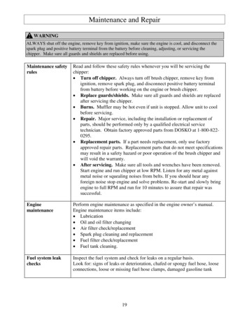
Controlling weldmetal dilutionDilution is the inevitable mixture of the base material and the weld metaldeposit when welding.The objective is to keep the dilution as low as possible to obtain the optimunproperties in the hard-facing deposit.Softer hard-facing materials display an increase in hardness when deposited on higher alloyed materials. This is due to carbon and alloy pick-up fromthe base material.The base material is, however, very often an unalloyed or low-alloy materialand several layers may be needed to achieve the required hardness. In general,two or three layers are enough.As the degree of dilution is a function not only of the welding process butalso of the procedure, the latter must be carried out in such a way that the leastpossible dilution takes place.Factors influencing dilution: Welding speed:Slow speed – high dilutionHigh speed – low dilution Welding polarity:DC- low dilutionAC intermediate dilutionDC high dilution Heat input:Low – low dilutionHigh – high dilution Welding technique:Stringer beads – low dilutionWeaved beads – high dilution Welding position:Vertical-up – high dilutionHorizontal, flat, vertical down – low dilution Number of layers:As more layers are deposited, the dilutiondecreases Type of weld metal:Over alloyed weld metal – less sensitive to dilution Electrode stick-out:(wires)Long stick-out – less dilution8
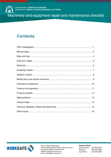
Microstructure hard-facing weld metal: OK 84.78, chrome carbide.9
The use of buffer layersand build-up layersBuffer layersBuffer layers are used as intermediate deposits between the base material andthe actual hard-facing weld metal to: ensure good bonding with the base material avoid hydrogen-induced underbead cracking even on preheated workpieces minimize the consequences of stress limit the effect of dilution avoid spalling in subsequent hard layers prevent possible cracks in the hard-facing layer running into the basematerialAustenitic consumables are widely used as ductile buffer layers in hardfacing. The choice of consumable depends on the base material and type ofsurfacing. See the table below.Consumables for buffer layersBase materialApplicationSMAWFCAW/GMAW14% Mn-steelWorn surfaceCrack repairOK 67.45OK 68.82OK Tubrodur 14.71OK Autrod 16.75Low-alloyed1 layer hard-facing,no impact wearNo buffer layerHardenablesteels2 layers hard-facing, OK 67.45impact wearOK Tubrodur 14.712 layers Co andNi alloysOK 67.45 orOK 68.82OK Tubrodur 14.71 orOK Autrod 16.751 layer hard-facing,no impact wearNo buffer layer2 layers hard-facing, OK 67.45impact wearOK Tubrodur 14.711–2 layers Co and Ni OK 67.45 oralloysOK 68.82OK Tubrodur 14.71 orOK Autrod 16.755–12%Cr steels Co and Ni alloys,for claddingOK 67.452–17%Cr steels Matching surfacingalloysNo buffer layerPreheating, see Table 7 on page 108.Cast iron1–2 layershard-facingOK 67.45 orOK 68.82OK Tubrodur 14.71 orOK Autrod 16.75Hard-facingOK 92.60OK Tubrodur 15.66See table 2 on page 91 for further product data.10OK Tubrodur 14.71
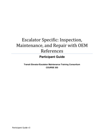
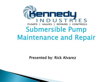
When harder surfacing materials are used on soft base material such as mildsteel, there is a tendency for the hard-facing layer to sink under high loadconditions, Figure A. This may result in the hard-facing material spalling off. Toprevent this, a strong, tough material is deposited on the part prior to hardfacing, Figure B.Hard-facingBuffer layerFigure AFigure BOK 83.28 and OK Tubrodur 15.40 are suitable build-up/buffering materials.Depending on the base material, other types of buffer layer may be recommended.When hard-facing with brittle alloys those containing chromium carbidesand cobalt-based alloys, it is recommended first to buffer one or two layerswith an austenitic consumable. This causes compression stress in subsequentlayers during cooling and thus reduces the risk of cracks in the hard weldmetal.Many hard-facing deposits contain “relief cracks”. They are not harmful tothe hard-facing, but there is a danger that, under heavy impact or flexing, thecracks will propagate into the base material, Figure C. This tendency is mostpronounced where the base material is a high strength steel. The use of atough bufferlayer will prevent this crack propagation, Figure D. Suitable consumables are OK 67.45 or OK 68.82 or OK Tubrodur 14.71 or OK Autrod 16.75,Figure B.Figure CFigure D11
Build-up layersIf a workpiece is badly worn, one possible method is to rebuild it to its originalform before hard-facing using the same type of alloy as the base material.Another method is to alternate hard and ductile deposits, see figure below.Consumables for build upAlloy typeSMAWFCAWSAWLow carbon/Low alloyOK 83.28OK 83.29OK Tubrodur 15.40OK Tubrodur 15.40/ OK Autrod 13.89OK Flux 10.71GMAWBuild-up alloys have good resistance to impact wear but, quite naturally,moderate resistance to abrasive wear.Depending on the base material, other types may be recommended.Typical applications are hammers crushers excavator teeth cold shearing ;;;;;;;;;;;;;;;;;;;;Hard;;;Ductile
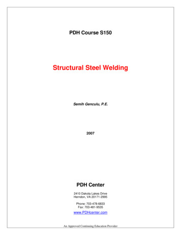
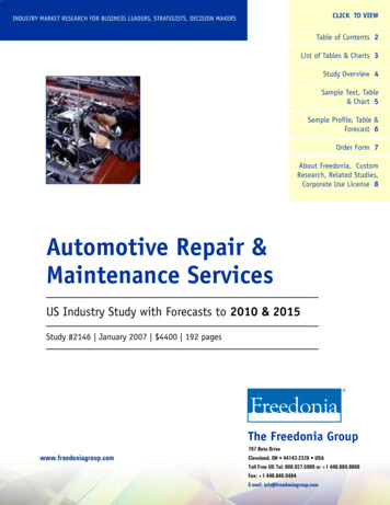
Engine block. Cast iron repair using OK 92.18 and OK 92.60.13
Welding cast ironGeneralCast iron comprises alloys of iron with a carbon content of 2– 5%, a siliconcontent of 1– 3% and up to 1% manganese.Cast iron exhibits low ductility, low hardness and low strength and isgenerally a very brittle material. To improve these properties, cast iron is veryoften alloyed or heat-treated.The types of cast iron which are mainly used today are: grey iron nodular iron malleable iron compacted graphite iron white ironThe high carbon content affects its weldability considerably. Because of therange of properties of cast iron, weldability varies accordingly. Some types arecasuall
welding can follow without any further preparation. Preparation in stainless steel and manganese steel may, however, require a little grinding. Note: The electrode is not designed to produce a weld metal. The electrode is available in 3.25, 4.0 and 5.0 mm. Applications OK 21.03 is suitable for gouging when welding on site and when equipment for carbon arc gouging is impractical. It is .