Transcription
INSTALLATION INSTRUCTIONSFan CoilsFEM4X, FEM4P, REM4X, FXM4XThese instructions must be read and understood completely before attempting installation.Safety Labeling and Signal WordsDANGER, WARNING, CAUTION, andNOTESignal Words in ManualsThe signal word WARNING is used throughout thismanual in the following manner:The signal words DANGER, WARNING,CAUTION, and NOTE are used to identify levels ofhazard seriousness. The signal word DANGER isonly used on product labels to signify an immediatehazard. The signal words WARNING, CAUTION,and NOTE will be used on product labels andthroughout this manual and other manuals that mayapply to the product.DANGER - Immediate hazards which will result insevere personal injury or death.WARNING - Hazards or unsafe practices whichcould result in severe personal injury or death.CAUTION - Hazards or unsafe practices whichmay result in minor personal injury or product orproperty damage.NOTE - Used to highlight suggestions which willresult in enhanced installation, reliability, oroperation.WARNING!The signal word CAUTION is used throughout thismanual in the following manner:CAUTION!Signal Words on Product LabelingSignal words are used in combination with colors and/orpictures on product labels.TABLE OF CONTENTSINTRODUCTION . . . . . . . . . . . . . . . . . . . . . . . . . . . . . . .LOCATION . . . . . . . . . . . . . . . . . . . . . . . . . . . . . . . . . . . .HEATER PACKAGES . . . . . . . . . . . . . . . . . . . . . . . . . . .AIR DUCTS . . . . . . . . . . . . . . . . . . . . . . . . . . . . . . . . . . .ELECTRICAL CONNECTIONS . . . . . . . . . . . . . . . . . .REFRIGERANT TUBING . . . . . . . . . . . . . . . . . . . . . . . .REFRIGERANT FLOW- CONTROL DEVICE . . . . . .REFRIGERANT METERING DEVICE . . . . . . . . . . . . .CONDENSATE DRAINS . . . . . . . . . . . . . . . . . . . . . . . .ACCESSORIES . . . . . . . . . . . . . . . . . . . . . . . . . . . . . . . .SEQUENCE OF OPERATIONS . . . . . . . . . . . . . . . . . .START- UP PROCEDURE . . . . . . . . . . . . . . . . . . . . . .CARE AND MAINTENANCE . . . . . . . . . . . . . . . . . . . . .AIRFLOW PERFORMANCE TABLES . . . . . . . . . . . . .R- 410A QUICK REFERENCE GUIDE . . . . . . . . . . . .2227710101111121313131417!WARNINGPERSONAL INJURY, AND/OR PROPERTY DAMAGEHAZARDFailure to carefully read and follow this warning couldresult in equipment malfunction, property damage,personal injury and/or death.Installation or repairs made by unqualified persons couldresult in equipment malfunction, property damage,personal injury and/or death.The information contained in this manual is intended foruse by a qualified service technician familiar with safetyprocedures and equipped with the proper tools and testinstruments.Installation must conform with local building codes andwith the National Electrical Code NFPA70 current edition.Specifications are subject to change without notice.496 01 5503 014/20/18
INSTALLATION INSTRUCTIONSFan Coils: FEM4X, FEM4P, REM4X, FXM4XINTRODUCTIONModels FEM4X, FEM4P, and REM4X are for R- 410Arefrigerant and can be used for upflow, horizontal left or right,and downflow applications (accessory kit required fordownflow). FEM and FXM units are designed to meet cabinetair leakage of less than 2% at 0.5 inches W.C. and cabinetair leakage less than 1.4% at 0.5 inches W.C. when testedin accordance with ASHRAE 193 standard.FEM4P models are available for system sizes 1- 1/2 - 4 tons(18,000 - 48,000 BTUH) nominal cooling capacity. FEM4Puse a refrigerant piston metering device with an ECM.FEM4X and FXM models are available for system sizes1- 1/2 - 5 tons (18,000 - 60,000 BTUH) nominal coolingcapacity. All models use an ECM motor and have afactory- installed and appropriately sized hard shut- off TXVmetering device and are for R- 410A refrigerant ONLY.REM4X models are available for system sizes 1- 1/2 through5 tons (18,000 - 60,000 BTUH) nominal cooling capacity. Allmodels use an ECM motor and have a factory- installed andappropriately sized hard shut- off R- 410A TXV meteringdevice used for R- 410A refrigerant ONLY.FEM and REM models require a field supplied air filter.Factory approved electric heater packages are available insizes 3kW through 30kW. See Product Specificationliterature for available accessory kits.LOCATIONSelect the best position which suits the installation siteconditions. The location should provide adequate structuralsupport, space in the front of the unit for service access,clearance for return air and supply duct connections, spacefor refrigerant piping connections and condensate drain lineconnections. If heaters are being installed make sureadequate clearance is maintained from supply duct work.Nuisance sweating may occur if the unit is installed in a highhumidity environment with low airflow. On these installations awrap of 2” (51mm) fiberglass insulation with a vapor barrier isrecommended.NOTE: Internal filter can be accessed from separate filterdoor. If the filter can NOT be easily accessed, a remote filteris recommended. Refer to ACCA Manual D for remote filtersizing.!WARNINGNOTE: FEM Units that require a kit to meet low leakrequirements have a gasket kit automatically included withshipment.Table 1 - Gasket Kit RequirementUnit SizeFEM - Kit Needed?FXM - Kit es048NoYes060NoNoSee ClearancesREQUIRED CLEARANCES - ALL MODELS inches(mm)All Sides0NoHeatersFrom Supply Duct0All Sides0From First 3 feet of Supply Duct to1 (25)WithCombustiblesHeatersFrom Supply Duct to Combustibles0after 3 feetHEATER PACKAGESFactory approved, field installed, UL listed heater packagesare available from the equipment supplier. See unit ratingplate for a list of factory approved heaters. Heaters that arenot factory approved could cause damage which would notbe covered under the equipment warranty.POSITION UNITUnit can stand or lie on floor, or hang from ceiling or wall.Allow space for wiring, piping, and servicing unit.!FIRE HAZARDFailure to maintain proper clearances could result in personalinjury, death, and/or property damage.When heaters are installed, maintain clearances from combustible materials as specified on unit rating plate. Do not useplastic lined or combustible flexible ducting within 36 inchesof the supply end of the fan coil.Refer to Table 1. Install the FEM fan coil with theaccompanying kit to ensure compliance with low leak2requirements of less than 2% cabinet leakage rate at 0.5inches W.C. and 1.4% cabinet leakage rate at 0.5 inchesW.C. when tested in accordance with ASHRAE 193standard.CAUTIONPROPERTY DAMAGE HAZARDFailure to follow this caution may result in propertydamage.A field fabricated auxiliary drain pan, with a separate drainis REQUIRED for all installations over a finished livingspace or in any area that may be damaged by overflowfrom a restricted main drain pan. In some localities, localcodes require an auxiliary drain pan for ANY horizontalinstallation.Specifications are subject to change without notice.496 01 5503 01
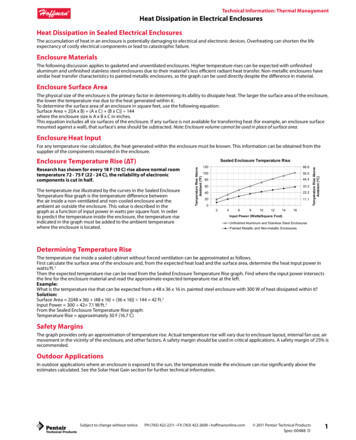
INSTALLATION INSTRUCTIONSFigure 1Fan Coils: FEM4X, FEM4P, REM4X, FXM4XModular Unit AssemblyA. UPFLOW INSTALLATIONIf return air is to be ducted through a floor, set unit on floorover opening and use 1/8 to 1/4 inch thick (3 to 6 mm thick)fireproof resilient gasket between duct, unit, and floor.Side return is a field option on slope coil models. Cut openingper dimensions shown in Figure 2. A field- supplied bottomclosure is required.BLOWER BOXSLOPE COIL UNITSMODELAFEM18, REM1812” (305mm)2 SCREWS2 SCREWSFXM18, FEM24, FXM24, REM24,FEM30, REM30, FEM36, REM36FXM30REAR CORNERBRACKET2 SCREWSCOIL BOXFigure 217” (432mm)19” (483mm)B. MODULAR UNITSFEM4X6000B, REM4X6000B, and FXM4X4800/6000 fancoils are two- piece modular units. This allows for modularunits to be disassembled and components moved separatelyto installation area for reassembly. This processaccommodates small scuttle holes and limiting entrances toinstallation sites (Figure 1).Upflow InstallationFIELD SUPPLIEDSUPPLY DUCTPOWER ENTRYOPTIONSLOW VOLTENTRYOPTIONSFRONT SERVICE CLEARANCE18 - 48 models 21” (533 mm)60 model 24” (610 mm)A- COILUNITSUPFLOW/DOWNFLOWSECONDARY DRAINUPFLOW/DOWNFLOWPRIMARY DRAIN1½”19”2½”(64mm)(483mm)AFIELD MODIFIEDSIDE RETURNLOCATION FORSLOPE COILUNITS ONLYUPFLOW/DOWNFLOWSECONDARY DRAINUPFLOW/DOWNFLOWPRIMARY DRAIN496 01 5503 01FIELD SUPPLIEDRETURN PLENUMSpecifications are subject to change without notice.3
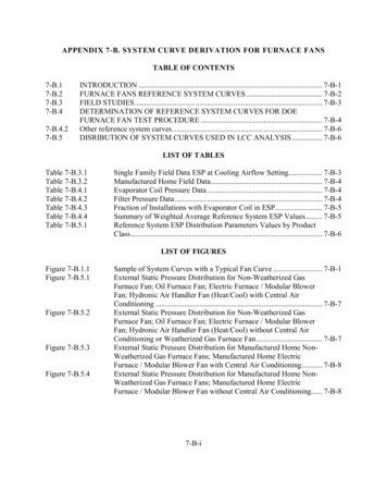
INSTALLATION INSTRUCTIONSFan Coils: FEM4X, FEM4P, REM4X, FXM4XC. DOWNFLOW INSTALLATIONCAUTION!PRODUCT OR PROPERTY DAMAGE HAZARDFailure to follow this caution may result in product orproperty damage.The conversion of the fan coil to downflow requires specialprocedures for the condensate drains on both A- coil andSlope- coil units. The vertical drains have an overflow holebetween the primary and secondary drain holes. This holeis plugged for all applications except downflow, and mustbe used for downflow.Failure to follow instructions could result in personal injuryor product and property damage.!WARNINGDuring the conversion process, remove the plastic capcovering the vertical drains only and discard.Remove the plug from the overflow hole and discard.At completion of the downflow installation, caulk around thevertical pan fitting to door joint to retain low air leakperformance of the unit.NOTE: Gasket kit number (EBAC01GSK) is also required forall downflow applications to maintain low air leak/low sweatperformance.D. HORIZONTAL INSTALLATIONUnit must NOT be installed with access panels facing up ordown. Access panels must only face to the side.STRUCTURAL DAMAGEFailure to follow this warning could result in personalinjury or death, or property damage.Combustible floor base is required when installing in adownflow application with electric heat strips.Structural damage could occur if manufacturer’sdownflow base accessory kit is not use when installing ina downflow application.In this application, field conversion of the evaporator coil isrequired using accessory Downflow Kit along with anFigure 3accessory Base Kit. Set unit on floor over opening and use1/8” to 1/4” thick fireproof resilient gasket between duct, unit,and floor. Refer to installation instructions packaged withaccessory kit. See Product Specification literature for kit partnumbers.All models are factory built for horizontal left installation (referto Figure 3 and Figure 4). They can be field converted tohorizontal right (accessory Gasket Kit required, see ProductSpecification literature for part number). Refer to Figure 5and Figure 6.NOTE: When suspending unit from ceiling, dimples in casingindicate suitable location of screws for mounting metalsupport straps (refer to Figure 3).NOTE: For optimum condensate drainage performance inhorizontal installations, unit should be leveled along its lengthand width.Slope Coil In Horizontal Left Application (factory configuration)A- COILHORIZONTAL YDRAINFRONT SERVICE CLEARANCE(FULL FACE OF UNIT)18 - 48 models 21” (533mm)60 model 24” (610mm)SECONDARYDRAINLOW VOLTENTRYOPTIONS1¾” (45mm)FILTER fications are subject to change without notice.496 01 5503 01
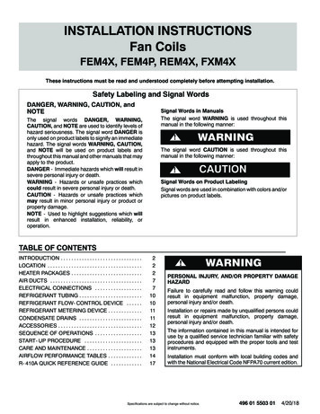
INSTALLATION INSTRUCTIONSFigure 4Fan Coils: FEM4X, FEM4P, REM4X, FXM4XA- Coil in Horizontal Left Application (factory configuration)ACOILBRACKETFACTORY SHIPPEDHORIZONTAL LEFTAPPLICATIONCOILSUPPORTRAILBCDRAIN PANSUPPORTBRACKETCOILBRACKETHORIZONTALDRAIN PANPRIMARY DRAINHORIZONTAL LEFTAIR SEALASSEMBLYREFRIGERANTCONNECTIONSHorizontal Right Conversion of Units With Slope Coils1. Remove blower and coil access panel and fitting panel(refer to Figure 5).2. Remove coil mounting screw securing coil assemblyto right side casing flange.3. Remove coil assembly.4. Lay fan coil unit on its right side and reinstall coilassembly with condensate pan down (refer to Figure 5).Figure 5SECONDARY DRAINHORIZONTAL LEFT5. Attach coil to casing flange using coil mounting screwpreviously removed.6. Align holes with tubing connections and condensatepan connections, and reinstall access panels andfitting panel. After brazing, make sure liquid andsuction tube grommets are in place to prevent airleaks and cabinet sweating.Conversion for Horizontal Right Applications - Slope CoilCOIL MOUNTINGSCREWBLOWERASSEMBLYCOIL SUPPORT RAILSLOPE COILDRAINPANREFRIGERANTCONNECTIONSPRIMARY DRAINSECONDARY DRAIN496 01 5503 01Specifications are subject to change without notice.5
INSTALLATION INSTRUCTIONSFan Coils: FEM4X, FEM4P, REM4X, FXM4XHorizontal Right Conversion of Units With A- Coils1. Remove blower and coil access panel and fitting panel(refer to Figure 6).2. Remove coil mounting screw securing coil assemblyto right side casing flange.3. Remove coil assembly.4. Lay fan coil unit on its right side and reinstall coilassembly with condensate pan down (refer toFigure 6).5. Remove horizontal drain pan support bracket from coilsupport rail on left side of unit and reinstall on coilsupport rail on right side of unit.6. Convert air- seal assembly for horizontal right (refer toFigure 6).a. Remove air- seal assembly from coil by removing 4screws.b. Remove coil drip flanges from A- coil and reinstall onright side of coil (same side as horizontal drain pan).c. Remove filler plate (A) and install air splitter (B) inplace of filler plate.d. Install filler plate (A) as shown in horizontal rightapplication.e. Remove condensate troughs (C) and install onopposite tube sheets.f. Install hose onto plastic spout.7. Install horizontal pan on right side of coil assembly.8. Slide coil assembly into casing. Be sure coil bracket oneach corner of vertical pan engages coil support rails.9. Reinstall 2 snap- in clips to correctly position andsecure coil assembly in unit. Be sure clip with largeoffsets is used on right side of unit to secure horizontalpan.10. Remove 2 oval coil access panel plugs and reinstallinto holes on left side of coil access panel and fittingpanel.11. Remove insulation knockouts on right side of coilaccess panel.12. Reinstall access fitting panels, aligning holes withtubing connections and condensate pan connections.Be sure to reinstall metal clip between fitting panel andvertical condensate pan.13. After brazing, make sure liquid and suction tubegrommets are in place to prevent air leaks and cabinetsweating.Conversion for Horizontal Right Applications - A- CoilFigure 6AREFRIGERANTCONNECTIONSAIR AILBCCOILBRACKETDRAIN TALDRAIN PANPRIAMRY DRAINHORIZONTAL RIGHTSECONDARY DRAINHORIZONTAL RIGHT6Specifications are subject to change without notice.496 01 5503 01
INSTALLATION INSTRUCTIONSFan Coils: FEM4X, FEM4P, REM4X, FXM4XE. MANUFACTURED HOUSING AND MOBILE HOMEAPPLICATIONS1. Fan coil unit must be secured to the structure usingfield- supplied hardware.2. Allow a minimum of 24 inches (610mm) clearancefrom access panels.3. Recommended method of securing for typicalapplications:a. If fan coil is away from wall, attach pipe strap to topof fan coil using No. 10 self tapping screws. Anglestrap down and away from back of fan coil, removeall slack, and fasten to wall stud of structure using5/16” lag screws. Typical both sides of fan coil.b. If fan coil is against wall, secure fan coil to wall studusing 1/8” (3mm) wide right- angle brackets. Attachbrackets to fan coil using No. 10 self tapping screwsand to wall stud using 5/16” lag screws (refer toFigure 7).Figure 8BLOWER BOX2 SCREWS2 SCREWSREAR CORNERBRACKETNOTE: Modular units can be disassembled and components moved separately to installation area for reassembly. This process accommodates small scuttleholes and limiting entrances to installation sites (refer to Figure 8).Figure 72 SCREWSCOIL BOXMobile Home or ManufacturedHousing Applications4” (102mm) MAXSECURE FAN COIL TO STRUCTUREUNIT AWAY FROM WALLPIPE STRAP(TYPICAL BOTH SIDES)ORUNIT AGAINST WALL1/8” (3mm) INCH THICK ANGLEMOUNTING BRACKET(TYPICAL BOTH SIDES)DOWN FLOWBASE KITSECURE UNIT TO FLOORANGLE BRACKET OR PIPE STRAP4” (102mm) MAX496 01 5503 01Removal of Brackets onModular UnitsAIR DUCTSConnect supply- air duct over the outside of 3/4” flangesprovided on supply- air opening. Secure duct to flange usingproper fasteners for type of duct used, and seal duct- to- unitjoint.It is a recommendation, but not a requirement, to use flexibleconnections between ductwork and unit to preventtransmission of vibration. When electric heater is installed,use heat- resistant material for flexible connector betweenduct work and unit at discharge connection. Duct workpassing through unconditioned space must be insulated andcovered with vapor barrier.Duct Work Acoustical TreatmentMetal duct systems that do not have a 90 degree elbow and10 feet of main duct before first branch takeoff may requireinternal acoustical insulation lining. As an alternative, fibrousduct work may be used if constructed and installed inaccordance with the latest edition of SMACNA constructionstandard on fibrous glass ducts. Both acoustical lining andfibrous duct work shall comply with National Fire ProtectionAssociation as tested by UL Standard 181 for Class 1 airducts.Specifications are subject to change without notice.7
INSTALLATION INSTRUCTIONSFan Coils: FEM4X, FEM4P, REM4X, FXM4XELECTRICAL CONNECTIONSThese Fan Coils do not have a printed circuit board (PCB), theyhave a low voltage circuit protective fuse (3 amp) inline on thewire harness. Speed selections are made at the fan motor withthe Blue wire. The motor is pre- programmed with thetime- delay circuit on some of the speed taps. (See Page 9,Section D)Before proceeding with electrical connections, make certainthat supply voltage, frequency, phase, and circuit ampacity areas specified on the unit rating plate. See unit wiring label forproper field high and low voltage wiring.!WARNINGELECTRICAL SHOCK or UNIT DAMAGE HAZARDFailure to follow this warning could result in personal injury,death, and/or unit damage.If a disconnect switch is to be mounted on unit, select alocation where drill and fasteners will not contact electricalor refrigeration components.Make all electrical connections in accordance with the NECand any local codes or ordinances that may apply. Usecopper wire only. The unit must have a separate branchelectric circuit with a field- supplied disconnect switch locatedwithin sight of and readily accessible from the unit.NOTE: When a pull- out type disconnect is removed from theunit, only the Load side of the circuit is de- energized. TheLine side remains live until the main (remote) disconnect isturned off.!WARNING3. When installing an electric heater, remove and discardpower plug (if equipped) from fan coil and connectmale plug from heater to female plug from unit ctions.)B. 24V CONTROL SYSTEMConnection to UnitWire low- voltage in accordance with wiring label on theblower (also refer to Figure 9 through Figure 12). Use 18AWG color- coded, insulated (35 C minimum) wire to makethe low- voltage connections between the thermostat, theunit, and the outdoor equipment. If the thermostat is locatedmore than 100 feet from the unit (as measured along the lowvoltage wire), use 16 AWG color- coded, insulated (35 Cminimum) wire. All wiring must be NEC Class 1 and must beseparated from incoming power leads. Refer to outdoor unitwiring instructions for additional wiring recommendations.Heater StagingIf electric heat staging is required, a multi- stage heatingroom thermostat is required. Consult your equipmentsupplier for a suitable thermostat.Manufactured HousingIn manufactured housing applications, the Code of FederalRegulations, Title 24, Chapter XX, Part 3280.714 requiresthat supplemental electric heat be locked out at outdoortemperatures above 40 F (4 C), except for a heat pumpdefrost cycle. Refer to Figure 12 for typical low- voltagewiring with outdoor thermostat.Wiring Layout - Air Conditionin
INSTALLATION INSTRUCTIONS Fan Coils: FEM4X, FEM4P, REM4X, FXM4X 496 01 5503 01 Specifications are subject to change without notice. 3 Figure 1 Modular Unit Assembly 2 SCREWS 2 SCREWS REAR CORNER BRACKET BLOWER BOX COIL BOX 2 SCREWS A. UPFLOW INSTALLATION If return air