Transcription
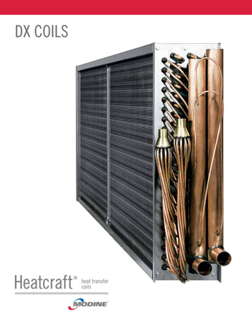
DX Coils
Contents and NomenclatureNomenclature. 2Evaporator Coil TypesEN. 3EF. 3ER. 3EJ. 3EK. 3Evaporator ConstructionConnections. 4Tubing. 4Headers. 4Tube Supports. 4Coil Case. 5Fins. 5EngineeringLiquid Overfeed Evaporators. 6General Formulas. 6Basic Vapor Compress Cycle. 7Nomenclature55345 EN1406Tube Outside Diameter0.375”0.500”0.625”E Coil TypeE EvaporatorN Standard Circuit RatioQ 1/4 serpH 1/2 serpL 3/4 serpB 5/6 serpS 1 serpC 1 1/4 serpM 1 1/2 serpD 2 serp14 Fins Per Inch06 Rows DeepC Fin DesignA - flat (Al, Cu)B - corrugated (Al, Cu)C - sine wave (Al, Cu)D - raised lance (Al) 3/8 and 1/2F - flat (SS, CS)G - corrugated (SS, CS)H - sine wave (SS, CS, Al, Cu)24.00 Fin Height (in)minimum of 6 inches144.00 Finned Length (in)minimum of 6 inches2C 24.00 x144.00
Evaporator Coil TypesEvaporator coils are designed and engineered for efficient operation with all refrigerants. The performance capabilities are excellent forcomfort cooling, process refrigeration, and moisture control dehumidifying.Direct expansion type evaporator coils are engineered and designed to deliver the maximum possible heat transfer efficiency under alloperating conditions. The wide variety of circuiting available offers the opportunity to provide the best circuit for peak coil performance.All evaporator coils are counter flow circuited and equipped with pressure type distributors, and all distributor tubes are of equal lengthto assure equal distribution of refrigerant to each circuit. Circuiting for face control and row control is also available as standard on awide variety of coils.ENEJModel Type EN (Figure 1), is used for applications where capacitycontrol is not required. Single or multiple distributors are useddepending on the number of circuits required.Figure 1 - EN NormalRows 2, 3, 4, 5, 6, 8, 10, 12Right Hand shownModel Type EJ (Figure 4) coils come with interlaced circuiting.This form of capacity control utilizes two distributors with eachfeeding every other tube in the first row of the coil. Each distributor has a separate suction connection. Type EJ coils are normallyfurnished with two distributors and two suction connectionsoffering 50% capacity reduction capabilities.Figure 4 - EJ InterlacedRows 3, 4, 6, 8, 10, 12Right Hand shownEFModel Type EF (Figure 2) is used for face control. Face Control isthe simplest form of capacity control. Type EF coils are normallyfurnished with two distributors and two suction connections offering 50% capacity reduction capabilities.Figure 2 - EF Face ControlRows 2, 3, 4, 5, 6, 8, 10, 12Right Hand shownEKModel Type EK (Figure 5) for applications that require face controland interlaced circuits, this model type is recommended. Interlaced face control normally utilizes four distributors and foursuction connections offering 25, 50 and 75% capacity reductioncapabilities.Figure 5 - EK Interlaced Face ControlRows 4, 6, 8, 10, 12Right Hand ShownERModel Type ER (Figure 3) offers a row control option for six rowevaporators only. These coils are split two rows and four rowswhich offer approximately a 50% capacity reduction.Figure 6 - Indicates the dimensional data needed to quote and build the coilFigure 3 - ER Row ControlRows 6Right Hand shown3
Evaporator ConstructionConnectionsHEADERSUniversal connection coils have two supply suction connections.The actual supply connection should be located at the bottom ofthe coil on the entering air side when installed to insure proper oilreturn to the compressor. The coil is both left and right hand. Thisoption is used when the coil hand is not available or if the coilis to be used as a backup for quick replacement of either a rightor left hand coil. Using universal connections can cut inventoryby providing the flexibility of one coil for either hand connection.Upon installation the extra connections are capped since they arenot needed.BRAZED COPPER TUBES-TO-COPPER HEADER JOINTConnections are constructed of carbon steel or stainless steelbutt-weld or copper sweat material (see Table 1). Liquid supplyconnections are spaced evenly along the height of the coil and thesuction connections are located at the bottom of each compressorcircuit unless stated otherwise.Table 1 - Material OptionsMaterialHeaders shall be constructed from UNS 12200 seamless copperconforming to ASTM B75 and ASTM B251 for standard applications. Stainless steel headers will be constructed of 304L & 316L(ASTM-A249) Sch-5 or Sch-10. Carbon steel headers shall beconstructed of Sch-10 (ASTM-A135A) or Sch-40 (ASTM A53A).End caps shall be die-formed and installed on the inside diameterof the header such that the landed surface area is three times theheader wall thickness.Seamless copper tubes are brazed into heavy gauge seamlessdrawn copper headers. This combination of similar metals eliminates unequal thermal expansion and greatly reduces stress inthe tube-header joint. When possible, intruded tube holes in theheader allow an extra landed brazing surface for increased strengthand durability. The landed surface area is three times the coretube thickness to provide enhanced header-to-tube joint integrity.All core tubes are evenly extended within the inside diameter ofthe header no more than 0.12 inch. (See Figure 7)Copper Sweat UNS # 12200, ASTM B-75, with a H55 TemperStainless Steel 304L or 316L ASTM A312 Sch 40 or Sch 80Figure 7 - Brazed JointCarbon Steel A53A Sch 40Cupro-nickel UNS# C70600, 90/10, ASTM B-111Admiralty Brass UNS # C444000, ASTM B-111, Type BTUBINGTubing and return bends shall be constructed from seamlesscopper for standard construction or cupro-nickel, admiralty brass,stainless steel or carbon steel tubing forspecial applications. Copper tube tempershall be light annealed with a maximumgrain size of 0.040 mm and a maximumhardness of Rockwell 65 on the 15T scale.Tubes will be mechanically expanded toform an interference fit with the fin collars.See Table 5 for fin size and materialavailability. See Tables 1 and 2 for more tube and connectioninformation.Table 2 - Tubing InformationTubing TypeCopper4ConnectionsCopper SweatTube O.D.Tube Thickness0.3750.013, 0.016, 0.020, 0.025, 0.0300.5000.016, 0.022, 0.0300.6250.020, 0.025, 0.035, 0.0490.3750.012, 0.016Copper - RifledCopper Sweat0.5000.016Cupro-nickelCopper Sweat0.6250.020, 0.035, 0.049Admiralty BrassCopper Sweat0.6250.049Stainless SteelStainless Steel0.6250.035, 0.049, 0.065Carbon SteelCarbon Steel0.6250.035, 0.049,0.065TUBE SUPPORTSTube supports will be constructed of the same material as thecase, when possible and provided according to the following chart.Table 3 - Tube SupportsFinned Length (FL) 48 48 96 96 144 144Tube Supports0124
Evaporator ConstructionCOIL CASETable 6 - Fin InformationCasings and end plates are made from 16-gauge galvanized steelunless otherwise noted. Double-flanged casings on top and bottom of finned height are to be provided, when possible, to allowstacking of the coils. All sheet metal brakes shall be bent to 90degrees /- 2 degrees, unless specified otherwise. Coils shall beconstructed with intermediate tube support sheets fabricated froma heavy gauge sheet stock of the same material as the case, whenpossible.TubeO.D.Fin MaterialAL, CUTable 4 - Case MaterialGauge161412Galvanized Steel, ASTM A-924 and A-653XX*XCopper ASTM B-152XXXAluminum Alloy-3003, Embossed FinishAlloy-5052, Mill Finish (0.125 only)XXXStainless Steel 304L (or) 316L, 2B-Finish, ASTM A-240X*X*XFinSurfaceFPIA, B, C8-24H6-180.0060 ALD10-240.0075 AL, CUB, C6-220.0075 ALH6-180.0095 AL, CUA, B, C6-240.0060 AL, CU0.375"MaterialFinThickness0.0095 ALH6-160.0060 CUA, B, C8-180.0060 ALA, B, C7-180.00600.5"AL, CU0.00756-146-16H4-140.0060 CUA, B, C8-140.0060 ALA, B, C6-14AL, CUA, B, C5-14AL, CU, CS, SSF5-14G6-14AL, CU0.625"FINSCoils are built of plate-fin type construction providing uniformsupport for all coil tubes. Coils are manufactured with die-formedaluminum, copper, cupro-nickel, stainless steel or carbon steelfins (see Table 5) with self-spacing collars, which completely coverthe entire tube surface, providing metal-to-metal contact. Fins areself-space die-formed fins 4 through 14 fins/inch with a toleranceof /- 4%.6-18H0.0095AL, CU8-14A, B, C*Not available in pierce and flare header platesFigure 8 - Case StylesHA, B, C0.0075CS, SSG6-14AL, CU, CS, SSH6-14AL, CUA, B, C4-14AL, CUF4-14F5-14CS, SSAL, CU, CS, SS0.0095AL, CUCS, SSAL, CU0.0160G5-14H5-14H6-14A, B, F, G4-14Table 5 - Fin MaterialMaterialFin Thickness (in.)0.00600.00750.00950.0160Aluminum Alloy-1100XXXXCopper Alloy-110XXXXCupro-nickel 90/10 Alloy-706XStainless Steel 302-2BXXCarbon Steel ASTM A109-83XX5
EngineeringLIQUID OVERFEED EVAPORATORSLiquid overfeed evaporators perform the same function as a standard DX evaporator except that a mixture of liquid and vapor leavesthe coil in lieu of 100% vapor. This is achieved by feeding theevaporator more liquid than can be completely boiled off throughthe coil. The construction is slightly different in that, instead ofhaving a distributor that properly distributes refrigerant to all thecoil’s circuits, a liquid overfeed coil has a supply header with anorifice welded into each tap tube. These orifices are largest at thetop of the coil and get smaller going to the bottom of the coil. Because refrigerant is so light, gravitational pull has an effect on thedistribution of refrigerant in the coil so these orifices act as a wayto counteract this force. The liquid connection is located at the topof the coil and the suction connection is located at the bottom ofthe coil to ensure proper oil return. Since this coil requires a muchhigher refrigerant charge than a standard DX coil, this applicationis typically seen in ammonia systems.There are costs and benefits of this system that should be considered. The added costs involved would be in the initial installationand cost of equipment. This type of coil typically requires a refrigerant pump that will force more liquid through the coil than canbe evaporated. Also, since there is a mixture of liquid and vaporleaving the coil (and liquid refrigerant cannot be compressed), thismixture must be separated so that only pure vapor refrigerant is introduced into the compressor. This is typically done in a large tankwhere the mixture enters the tank at the side. The vapor refrigerantis pulled off the top of the tank while the liquid falls to the bottom.The final additional cost would be the added refrigerant charge dueto the tank, extra piping, and increased liquid refrigerant volume inthe system.The benefit can be seen in the annual operation of the system.The liquid overfeed application runs much more efficiently than astandard DX coil. Because there is liquid refrigerant throughout thecoil, it is ensured that there will be no dry surface on the interior ofthe coil tube. With a completely wetted interior tube surface, therefrigerant side heat transfer coefficient is increased. This meansthat more capacity can be generated out of less surface area.Also, since the refrigerant leaving the coil is at saturation, andnot superheated, the temperature of the refrigerant entering thecompressor is lowered. This results in lower compressor dischargetemperatures, which can both extend the life of the compressorand have the compressor run more efficiently.6GENERAL FORMULASTOTAL BTUH (Air Cooling)Total BTUH 4.5 x SCFM x (Total Heat Ent. Air - TotalHeat Lvg. Air)Where 4.5 Density Std. Air x Min./Hr.Density Std. Air 0.075 lbs./cu. ft.Min./hr. 60SENSIBLE BTUH (Air Cooling)Sensible BTUH 1.08 x SCFM x (Ent. Air DB - Lvg.Air DB)Where 1.08 (Specific heat of air) x (Minutes/Hr.) xDensity Std. AirSpecific heat 0.24 btu/lb.FMin./hr. 60Density Std. Air .075 Lbs./cu. ft.SENSIBLE TOTAL RATIOS/T Ratio Sensible BTUH Total BTUHLEAVING AIR TEMPERATURE (cooling)Lvg Air Temp. Ent. Air Temp. - (Sensible BTUH (1.08 x SCFM))FACE AREAFA (Sq. Ft.) (Fin Height x Finned Length) 144FACE VELOCITY (FPM)FPM SCFM Face Area (sq. ft.)MBH PER SQUARE FOOT OF FACE AREAMBH/Sq. Ft. Total BTUH (Face Area (Sq. Ft.) x 1000)Standard Conditions:Temperature 70 FPressure 14.69 psiDensity 0.075 lb/ft³
EngineeringBASIC VAPOR COMPRESSION CYCLEDiagram 1 - Vapor Compression CycleImportant in this cycle are the changes in pressure that results inchanges in the pressure/temperature relationship of the refrigerant. As the temperature of the refrigerant changes it is subjectedto air being moved over either the evaporator or condenser wherethe temperature difference between the refrigerant and air streamresult in a transfer of heat either into or away from the refrigerant.As this occurs, the refrigerant will change state in the cycle fromliquid to vapor and back again through the use of the compressorand expansion valve, where the change in pressure is accomplished. The term used to describe this is a “two phase” cycle.The basic refrigeration cycle is a continuous loop of changingrefrigerant pressures and temper
Galvanized Steel, ASTM A-924 and A-653 X X *X Copper ASTM B-152 X X X Aluminum Alloy-3003, Embossed Finish Alloy-5052, Mill Finish (0.125 only) X X X Stainless Steel 304L (or) 316L, 2B-Finish, ASTM A-240 X *X *X *Not available in pierce and flare header plates FINs Coils are built of plate-fin type construction providing uniform support for all coil tubes. Coils are manufactured with die .File Size: 325KBPage Count: 8