Transcription
Network visualization with RKatherine Ognyanova, www.kateto.netPOLNET 2015 Workshop, Portland ORContentsIntroduction: Network Visualization2Data format, size, and preparation4DATASET 1: edgelist . . . . . . . . . . . . . . . . . . . . . . . . . . . . . . . . . . . . . .4DATASET 2: matrix . . . . . . . . . . . . . . . . . . . . . . . . . . . . . . . . . . . . . . .5Network visualization: first steps with igraph5A brief detour I: Colors in R plots8A brief detour II: Fonts in R plots11Back to our main plot line: plotting networks12Plotting parameters . . . . . . . . . . . . . . . . . . . . . . . . . . . . . . . . . . . . . . . . 12Network Layouts . . . . . . . . . . . . . . . . . . . . . . . . . . . . . . . . . . . . . . . . . 17Highlighting aspects of the network . . . . . . . . . . . . . . . . . . . . . . . . . . . . . . . 24Highlighting specific nodes or links . . . . . . . . . . . . . . . . . . . . . . . . . . . . . . . 27Interactive plotting with tkplot. . . . . . . . . . . . . . . . . . . . . . . . . . . . . . . . . 29Other ways to represent a network . . . . . . . . . . . . . . . . . . . . . . . . . . . . . . . 30Plotting two-mode networks with igraph . . . . . . . . . . . . . . . . . . . . . . . . . . . .31Quick example using the network package35Interactive and animated network visualizations37Interactive D3 Networks in R . . . . . . . . . . . . . . . . . . . . . . . . . . . . . . . . . . 37Simple Plot Animations in R . . . . . . . . . . . . . . . . . . . . . . . . . . . . . . . . . . 38Interactive networks with ndtv-d3 . . . . . . . . . . . . . . . . . . . . . . . . . . . . . . . . 39Interactive plots of static networks . . . . . . . . . . . . . . . . . . . . . . . . . . . . 39Network evolution animations . . . . . . . . . . . . . . . . . . . . . . . . . . . . . . . 401
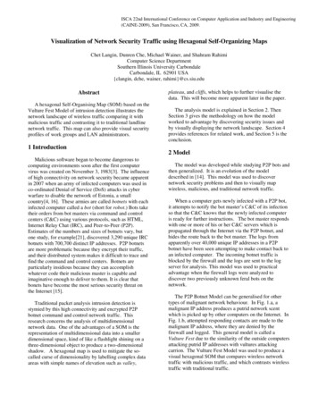
Introduction: Network VisualizationThe main concern in designing a network visualization is the purpose it has to serve. What are thestructural properties that we want to highlight?Network visualization goalsKey actors and linksStructural propertiesRelationship strengthCommunitiesThe network as a mapDiffusion patternsABNetwork maps are far from the only visualization available for graphs - other network representationformats, and even simple charts of key characteristics, may be more appropriate in some cases.Some network visualization typesNetwork MapsStatistical chartsArc diagramsHeat mapsHive plotsBiofabric2
In network maps, as in other visualization formats, we have several key elements that control theoutcome. The major ones are color, size, shape, and position.Network visualization controlsColorPositionSizeShapeHonorable mention: arrows (direction) and labels (identification)Modern graph layouts are optimized for speed and aesthetics. In particular, they seek to minimizeoverlaps and edge crossing, and ensure similar edge length across the graph.Layout aestheticsMinimize edge crossingNoUniform edge lengthYesNoPrevent overlapNoYesSymmetryYesNo3Yes
Note: You can download all workshop materials here, or visit kateto.net/polnet2015.Data format, size, and preparationIn this tutorial, we will work primarily with two small example data sets. Both contain data aboutmedia organizations. One involves a network of hyperlinks and mentions among news sources. Thesecond is a network of links between media venues and consumers. While the example data usedhere is small, many of the ideas behind the visualizations we will generate apply to medium andlarge-scale networks. This is also the reason why we will rarely use certain visual properties suchas the shape of the node symbols: those are impossible to distinguish in larger graph maps. Infact, when drawing very big networks we may even want to hide the network edges, and focus onidentifying and visualizing communities of nodes. At this point, the size of the networks you canvisualize in R is limited mainly by the RAM of your machine. One thing to emphasize though isthat in many cases, visualizing larger networks as giant hairballs is less helpful than providing chartsthat show key characteristics of the graph.This tutorial uses several key packages that you will need to install in order to follow along. Severalother libraries will be mentioned along the way, but those are not critical and can be skipped. Themain libraries we are going to use are igraph (maintained by Gabor Csardi and Tamas Nepusz),sna & network (maintained by Carter Butts and the Statnet team), and ndtv (maintained by ll.packages("ndtv")DATASET 1: edgelistThe first data set we are going to work with consists of two files, “Media-Example-NODES.csv” and“Media-Example-EDGES.csv” (download here.4
nodes - read.csv("Dataset1-Media-Example-NODES.csv", header T, as.is T)links - read.csv("Dataset1-Media-Example-EDGES.csv", header T, as.is T)Examine the data:head(nodes)head(links)nrow(nodes); length(unique(nodes id))nrow(links); nrow(unique(links[,c("from", "to")]))Notice that there are more links than unique from-to combinations. That means we have casesin the data where there are multiple links between the same two nodes. We will collapse all linksof the same type between the same two nodes by summing their weights, using aggregate() by“from”, “to”, & “type”:links - aggregate(links[,3], links[,-3], sum)links - links[order(links from, links to),]colnames(links)[4] - "weight"rownames(links) - NULLDATASET 2: matrixnodes2 - read.csv("Dataset2-Media-User-Example-NODES.csv", header T, as.is T)links2 - read.csv("Dataset2-Media-User-Example-EDGES.csv", header T, row.names 1)Examine the data:head(nodes2)head(links2)We can see that links2 is an adjacency matrix for a two-mode network:links2 - �——–Network visualization: first steps with igraphWe start by converting the raw data to an igraph network object. Here we use igraph’sgraph.data.frame function, which takes two data frames: d and vertices.5
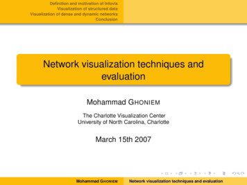
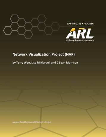
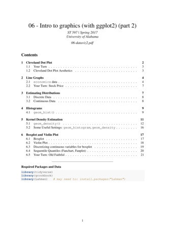
d describes the edges of the network. Its first two columns are the IDs of the source and thetarget node for each edge. The following columns are edge attributes (weight, type, label, oranything else). vertices starts with a column of node IDs. Any following columns are interpreted as nodeattributes.library(igraph)net - graph.data.frame(links, nodes, directed T)net## IGRAPH DNW- 17 49 -## attr: name (v/c), media (v/c), media.type (v/n), type.label##(v/c), audience.size (v/n), type (e/c), weight (e/n)The description of an igraph object starts with four letters:1.2.3.4.D or U, for a directed or undirected graphN for a named graph (where nodes have a name attribute)W for a weighted graph (where edges have a weight attribute)B for a bipartite (two-mode) graph (where nodes have a type attribute)The two numbers that follow (17 49) refer to the number of nodes and edges in the graph. Thedescription also lists node & edge attributes, for example: (g/c) - graph-level character attribute (v/c) - vertex-level character attribute (e/n) - edge-level numeric attributeWe also have easy access to nodes, edges, and their attributes with:E(net)V(net)E(net) typeV(net) media####The edges of the "net" objectThe vertices of the "net" objectEdge attribute "type"Vertex attribute "media"# You can also manipulate the network matrix directly:net[1,]net[5,7]Now that we have our igraph network object, let’s make a first attempt to plot it.plot(net) # not a pretty picture!6
s13s14s17s07s16s11 s12s06s04s08s10s03s01s02s09s15s05That doesn’t look very good. Let’s start fixing things by removing the loops in the graph.net - simplify(net, remove.multiple F, remove.loops T)You might notice that we could have used simplify to combine multiple edges by summingtheir weights with a command like simplify(net, edge.attr.comb list( Weight "sum","ignore" )). The problem is that this would also combine multiple edge types (in our data:“hyperlinks” and “mentions”).Let’s and reduce the arrow size and remove the labels (we do that by setting them to NA):plot(net, edge.arrow.size .4,vertex.label NA)7
A brief detour I: Colors in R plotsColors are pretty, but more importantly they help people differentiate between types of objects, orlevels of an attribute. In most R functions, you can use named colors, hex, or RGB values. In thesimple base R plot chart below, x and y are the point coordinates, pch is the point symbol shape,cex is the point size, and col is the color. To see the parameters for plotting in base R, check out?parplot(x 1:10, y rep(5,10), pch 19, cex 3, col "dark red")points(x 1:10, y rep(6, 10), pch 19, cex 3, col "557799")points(x 1:10, y rep(4, 10), pch 19, cex 3, col rgb(.25, .5, .3))You may notice that RGB here ranges from 0 to 1. While this is the R default, you can also set itfor to the 0-255 range using something like rgb(10, 100, 100, maxColorValue 255).We can set the opacity/transparency of an element using the parameter alpha (range 0-1):plot(x 1:5, y rep(5,5), pch 19, cex 12, col rgb(.25, .5, .3, alpha .5), xlim c(0,6))If we have a hex color representation, we can set the transparency alpha using adjustcolor frompackage grDevices. For fun, let’s also set the plot background to gray using the par() function forgraphical parameters.par(bg "gray40")col.tr - grDevices::adjustcolor("557799", alpha 0.7)plot(x 1:5, y rep(5,5), pch 19, cex 12, col col.tr, xlim c(0,6))8
If you plan on using the built-in color names, here’s how to list all of them:colors()grep("blue", colors(), value T)# List all named colors# Colors that have "blue" in the nameIn many cases, we need a number of contrasting colors, or multiple shades of a color. R comes withsome predefined palette function that can generate those for us. For example:pal1 - heat.colors(5, alpha 1)# 5 colors from the heat palette, opaquepal2 - rainbow(5, alpha .5)# 5 colors from the heat palette, transparentplot(x 1:10, y 1:10, pch 19, cex 5, col pal1)plot(x 1:10, y 1:10, pch 19, cex 5, col pal2)We can also generate our own gradients using colorRampPalette. Note that colorRampPalettereturns a function that we can use to generate as many colors from that palette as we need.9
palf - colorRampPalette(c("gray80", "dark red"))plot(x 10:1, y 1:10, pch 19, cex 5, col palf(10))To add transparency to colorRampPalette, you need to use a parameter alpha TRUE:palf - colorRampPalette(c(rgb(1,1,1, .2),rgb(.8,0,0, .7)), alpha TRUE)plot(x 10:1, y 1:10, pch 19, cex 5, col palf(10))Finding good color combinations is a tough task - and the built-in R palettes are rather limited.Thankfully there are other available packages for this:# If you don't have R ColorBrewer already, you will need to install rewer)display.brewer.all()This package has one main function, called brewer.pal. To use it, you just need to select thedesired palette and a number of colors. Let’s take a look at some of the RColorBrewer palettes:display.brewer.pal(8, "Set3")10
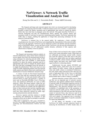
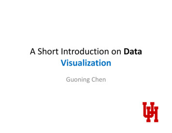
display.brewer.pal(8, "Spectral")display.brewer.pal(8, "Blues")Using RColorBrewer palettes in plots:pal3 - brewer.pal(10, "Set3")plot(x 10:1, y 10:1, pch 19, cex 4, col pal3)A brief detour II: Fonts in R plotsUsing different fonts for R plots may take a little bit of work. This is especially true if you are usingWindows - Mac & Linux users can most likely skip all of this.In order to import fonts from the OS into R, we can use the ‘extrafont’ font)# Import system fonts - may take a while, so DO NOT run this during the workshop.font import()fonts() # See what font families are available to you now.loadfonts(device "win") # use device "pdf" for pdf plot output.Now that your fonts are available, you should be able to do something like this:11
library(extrafont)plot(net, vertex.size 30)plot(net, vertex.size 30, vertex.label.family "Arial Black" )s09s14s13s02 5s04s12s14s01s05s01s03s17s06s17s16s13s15When you save plots as PDF files, you can also embed the fonts:# First you may have to let R know where to find ghostscript on your machine:Sys.setenv(R GSCMD "C:/Program Files/gs/gs9.10/bin/gswin64c.exe")# pdf() will send all the plots we output before dev.off() to a pdf file:pdf(file "ArialBlack.pdf")plot(net, vertex.size 30, vertex.label.family "Arial Black" )dev.off()embed fonts("ArialBlack.pdf", outfile "ArialBlack embed.pdf")Back to our main plot line: plotting networksPlotting with igraph: the network plots have a wide set of parameters you can set. Those includenode options (starting with vertex.) and edge options (starting with edge.). A list of selectedoptions is included below, but you can also check out ?igraph.plotting for more information.The igraph plotting parameters include (among others):Plotting parameters12
darrow.modeOTHERmarginframemainsubNode colorNode border colorOne of “none”, “circle”, “square”, “csquare”, “rectangle”“crectangle”, “vrectangle”, “pie”, “raster”, or “sphere”Size of the node (default is 15)The second size of the node (e.g. for a rectangle)Character vector used to label the nodesFont family of the label (e.g.“Times”, “Helvetica”)Font: 1 plain, 2 bold, 3, italic, 4 bold italic, 5 symbolFont size (multiplication factor, device-dependent)Distance between the label and the vertexThe position of the label in relation to the vertex,where 0 right, “pi” is left, “pi/2” is below, and “-pi/2” is aboveEdge colorEdge width, defaults to 1Arrow size, defaults to 1Arrow width, defaults to 1Line type, could be 0 or “blank”, 1 or “solid”, 2 or “dashed”,3 or “dotted”, 4 or “dotdash”, 5 or “longdash”, 6 or “twodash”Character vector used to label edgesFont family of the label (e.g.“Times”, “Helvetica”)Font: 1 plain, 2 bold, 3, italic, 4 bold italic, 5 symbolFont size for edge labelsEdge curvature, range 0-1 (FALSE sets it to 0, TRUE to 0.5)Vector specifying whether edges should have arrows,possible values: 0 no arrow, 1 back, 2 forward, 3 bothEmpty space margins around the plot, vector with length 4if TRUE, the plot will be framedIf set, adds a title to the plotIf set, adds a subtitle to the plotWe can set the node & edge options in two ways - the first one is to specify them in the plot()function, as we are doing below.# Plot with curved edges (edge.curved .1) and reduce arrow size:plot(net, edge.arrow.size .4, edge.curved .1)13
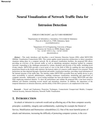
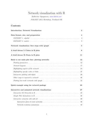
6# Set edge color to light gray, the node & border color to orange# Replace the vertex label with the node names stored in "media"plot(net, edge.arrow.size .2, edge.color "orange",vertex.color "orange", vertex.frame.color "#ffffff",vertex.label V(net) media, vertex.label.color "black")WashingtonPost.comNew York Post AOL.comNYTimes.comGoogle NewsUSA TodayYahoo NewsNY TimesLA TimesBBCWall Street JournalReuters.comWashington PostFOX NewsABCMSNBCCNNThe second way to set attributes is to add them to the igraph object. Let’s say we want to colorour network nodes based on type of media, and size them based on degree centrality (more links - larger node) We will also change the width of the edges based on their weight.# Generate colors base on media type:colrs - c("gray50", "tomato", "gold")V(net) color - colrs[V(net) media.type]# Compute node degrees (#links) and use that to set node size:deg - degree(net, mode "all")14
V(net) size - deg*3# We could also use the audience size value:V(net) size - V(net) audience.size*0.6# The labels are currently node IDs.# Setting them to NA will render no labels:V(net) label - NA# Set edge width based on weight:E(net) width - E(net) weight/6#change arrow size and edge color:E(net) arrow.size - .2E(net) edge.color - "gray80"E(net) width - 1 E(net) weight/12plot(net)We can also override the attributes explicitly in the plot:plot(net, edge.color "orange", vertex.color "gray50")15
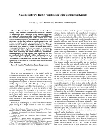
It helps to add a legend explaining the meaning of the colors we used:plot(net)legend(x -1.5, y -1.1, c("Newspaper","Television", "Online News"), pch 21,col "#777777", pt.bg colrs, pt.cex 2, cex .8, bty "n", ncol 1)NewspaperTelevisionOnline NewsSometimes, especially with semantic networks, we may be interested in plotting only the labels ofthe nodes:plot(net, vertex.shape "none", vertex.label V(net) media,vertex.label.font 2, vertex.label.color "gray40",vertex.label.cex .7, edge.color "gray85")FOX NewsMSNBC ABCWashington PostLA TimesCNNWall Street JournalNY TimesNYTimes.comBBCUSA TodayReuters.comYahoo NewsNew York PostGoogle NewsAOL.comWashingtonPost.com16
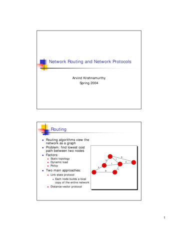
Let’s color the edges of the graph based on their source node color. We can get the starting nodefor each edge with the get.edges igraph function.edge.start - get.edges(net, 1:ecount(net))[,1]edge.col - V(net) color[edge.start]plot(net, edge.color edge.col, edge.curved .1)Network LayoutsNetwork layouts are simply algorithms that return coordinates for each node in a network.For the purposes of exploring layouts, we will generate a slightly larger 80-node graph. We use thebarabasi.game function which generates a simple graph starting from one node and adding morenodes and links based on a preset level of preferential attachment (how much new actors wouldprefer to form links to the more popular nodes in the network).net.bg - barabasi.game(80)V(net.bg) frame.color - "white"V(net.bg) color - "orange"V(net.bg) label - ""V(net.bg) size - 10E(net.bg) arrow.mode - 0plot(net.bg)17
You can set the layout in the plot function:plot(net.bg, layout layout.random)Or you can calculate the vertex coordinates in advance:l - layout.circle(net.bg)plot(net.bg, layout l)l is simply a matrix of x, y coordinates (N x 2) for the N nodes in the graph. You can easilygenerate your own:18
l - matrix(c(1:vcount(net.bg), c(1, vcount(net.bg):2)), vcount(net.bg), 2)plot(net.bg, layout l)This layout is just an example and not very helpful - thankfully igraph has a number of built-inlayouts, including:# Randomly placed verticesl - layout.random(net.bg)plot(net.bg, layout l)# Circle layoutl - layout.circle(net.bg)plot(net.bg, layout l)19
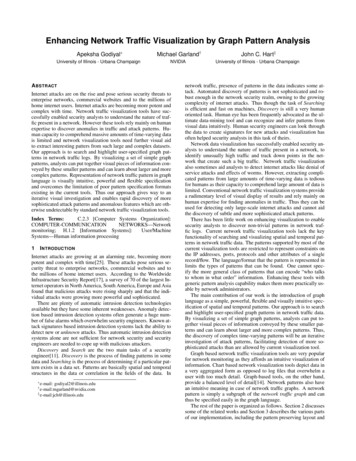
# 3D sphere layoutl - layout.sphere(net.bg)plot(net.bg, layout l)Fruchterman-Reingold is one of the most used force-directed layout algorithms out there.Force-directed layouts try to get a nice-looking graph where edges are similar in length and crosseach other as little as possible. They simulate the graph as a physical system. Nodes are electricallycharged particles that repulse each other when they get too close. The edges act as springs thatattract connected nodes closer together. As a result, nodes are evenly distributed through the chartarea, and the layout is intuitive in that nodes which share more connections are closer to each other.The disadvantage of these algorithms is that they are rather slow and therefore less often used ingraphs larger than 1000 vertices.Some parameters you can set for this layout include area (the default is the square of # nodes) andrepulserad (cancellation radius for the repulsion - the area multiplied by # nodes). Bothparameters affect the spacing of the plot - play with them until you like the results.You can also set the “weight” parameter which increases the attraction forces among nodes connectedby heavier edges.You will notice that the layout is not deterministic - different runs will result in slightly differentconfigurations. Saving the layout in l allows us to get the exact same result multiple times, which20
can be helpful if you want to plot the time evolution of a graph, or different relationships – andwant nod
Network visualization with R Katherine Ognyanova,www.kateto.net POLNET 2015 Workshop, Portland OR Contents Introducti