Transcription
Automated Reconstruction of Control Logic forProgrammable Logic Controller ForensicsSyed Ali Qasim1 , Juan Lopez Jr2 , Irfan Ahmed11Virginia Commonwealth University, Richmond VA 23284, USA{qasimsa, iahmed3}@vcu.edu2Oak Ridge National Lab Oak Ridge, TN 37830lopezj@ornl.govAbstract. This paper presents Similo, an automated scalable framework for control logic forensics in industrial control systems. Similo isdesigned to investigate denial of engineering operations (DEO) attacks,recently demonstrated to hide malicious control logic in a programmablelogic controller (PLC) at field sites from an engineering software (atcontrol center). The network traffic (if captured) contains substantialevidence to investigate DEO attacks including manipulation of controllogic. Laddis, a state-of-the-art forensic approach for DEO attacks, is abinary-logic decompiler for the Allen-Bradley’s RSLogix engineering software and MicroLogix 1400 PLC. It is developed with extensive manualreverse engineering effort of the underlying proprietary network protocoland the binary control logic. Unfortunately, Laddis is not scalable and requires similar efforts to extend on other engineering software/PLCs. Theproposed solution, Similo, is based on the observation that engineering software of different vendors are equipped with decompilers. Similois a virtual-PLC framework that integrates the decompilers with theirrespective (previously-captured) ICS network traffic of control logic. Itrecovers the binary logic into a high-level source code (of the programming languages defined by IEC 61131-3 standard) automatically. Similocan work with both proprietary/open protocols without requiring protocol specifications and the binary formats of control logic. Thus, it isscalable to different ICS vendors. We evaluate Similo on three PLCs oftwo ICS vendors, i.e. MicroLogix 1400, MicroLogix 1100, and ModiconM221. These PLCs support proprietary protocols and the control logics written in two programming languages: Ladder Logic and InstructionList. The evaluation results show that Similo can accurately reconstructa control logic from an ICS network traffic and can be used to investigatethe DEO attacks effectively.Keywords: Control System · SCADA · Forensics · PLC · ICS1IntroductionIndustrial control systems (ICS) monitor and control our critical infrastructuressuch as nuclear plant and gas pipelines. These systems were originally designed
Syed Ali Qasim et al.to be isolated environments with limited access to the outer world. Increasingly,they are now connected to the Internet and corporate networks, thereby makingthem vulnerable to cyber attacks [3, 18, 10, 19].Unfortunately, the current forensic capabilities are insufficient to investigatecyberattacks on ICS environments because these environments are significantlydifferent from traditional IT systems [1, 2]. They are connected with physicalprocesses, have the critical requirement of high availability, and use resourceconstrained computing devices, legacy operating system, and proprietary network protocols.An ICS consists of control center and field sites. The control center runsICS services such as human machine interface (HMI), historian, and engineering workstation. The fields sites have physical process, and computing devicessuch as sensors, actuators, and programmable logic controllers (PLCs). A PLCmaintains a desired actuator state by a control logic and observing the currentstate of a physical processes using sensor data. The PLC also communicates thesensor data and actuator state to control center over a communication channel.Recently, Senthivel et al. [16] present a new class of ICS attacks, namely,denial of engineering operations attack (DEO). In DEO I, an attacker compromises a control logic of a target PLC. When an engineering software attemptsto retrieve the control logic from the compromised PLC, it intercepts the trafficvia man-in-the-middle attack and replaces/removes the malicious logic from thecontrol logic in the network traffic before forwarding it to the software. Hence,the engineering software receives a normal (non-malicious) control logic. In DEOII, which is a variant of DEO I, the attacker replaces a legitimate instruction in acontrol logic with noise data such as 0xFFFFFF to make the engineering softwaremalfunction.The ICS network traffic contains substantial evidence to investigate DEO attacks including manipulation of control logic. The challenge is to reconstruct andtransform the binary control logic (in the traffic dump) into its high-level sourcecode. The closest effort in this direction is Laddis [16], which is a binary-logicdecompiler for the Allen-Bradleys RSLogix engineering software and MicroLogixPLC series. Unfortunately, Laddis is not scalable and requires manual reverseengineering to extend on other engineering software/PLCs.This paper presents Similo to recover a control logic from an ICS networktraffic automatically. Similo is based on the observation that engineering software of different vendors are equipped with a decompiler that transforms abinary control logic into a high-level language source-code. Similo is an automated and scalable framework (for control logic forensics), which utilizes theupload function of an engineering software to integrate a previously-capturednetwork traffic dump of a control logic with a decompiler in the engineeringsoftware. The framework does not require manual reverse engineering efforts forproprietary protocols and binary control logic. Thus, it is scalable.We evaluate Similo on 113 control logic programs at three different levels:packet-level, functional-level and source-code-level of control logic. We use theengineering software of two different vendors, Allen-Bradley and Modicon, and
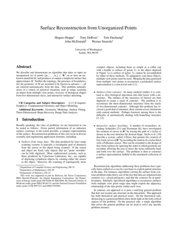
Control Logic Reconstruction for PLC Forensics(a) Ladder Logic(b) Instruction ListFig. 1: Different representations of a timer programthree PLCs supporting two IEC 61131-3 programming languages i.e., InstructionList and Ladder Logic and two proprietary protocols i.e., PCCC, and M221proprietary layer encapsulated in Modbus. The evaluation results show thatSimilo can engage an engineering software using an ICS network traffic dumpof a control logic including session establishment, echo messages and transferringof the control logic in the traffic dump to an engineering software. This results ina correct reconstruction and transformation of a control logic into a source-code.We further recreate DEO attacks on these PLCs and engineering software andutilize Similo to investigate them successfully.22.1BackgroundControl LogicProgrammable Logic Controller. PLCs are embedded devices that reside onfield-sites to control and monitor physical processes directly. A PLC has inputand output modules. The input module connects input devices such as sensorsthat provide temperature and pressure in a pipeline, level of liquid in a tank,etc. The output module connects with actuators to maintain the desired stateof a physical process. The control logic in a PLC processes the input to set theoutput. A PLC also supports network communication (such as Ethernet or serialport) to communicate with the ICS services in control center such as engineeringsoftware.PLC Programming. IEC 61131-3 defines five languages to write a controllogic. These languages can be divided into two categories, i) Textual, and ii)Graphical. Structured text, and Instruction list are textual while Ladder Logic,Functional Block Diagram, and Sequential Function Chart are graphical. Notethat for the purpose of evaluation, we select one language from each category i.eLadder logic (graphical) and Instruction List (textual).Ladder Logic. Ladder logic is a graphical language and is derived fromRelay Logic. The program is defined in the form of a graphical diagram. Ahorizontal line in a Ladder logic program is called rung. A rung comprises of a
Syed Ali Qasim et al.Fig. 2: DEO Attack I: Hiding infected ladder logic from the engineering softwarenumber of input and output instructions. An instruction defines an operation tobe performed by the processor [4].Figure 1a is a ladder logic program consisting of one rung and two instructions: 1) XIC (Examine if closed) on left is associated with the input addressI:0/0, 2) TON (timer on delay) on right. The timer instruction has three attributes, i) time base (the unit of time, 1.0 means one second). ii) Preset (maximum time to wait). iii) Accumulator (the time that has passed). It also has twocontrol bits, EN (enable) and DN (Done).When the program executes and the XIC is true, it will start the timer andEN will become true. The preset is 6 and the time-base is one second. Whenthe timer completes 6 seconds, the DN bit turns to true and the accumulatoris changed to the preset value.Instruction List. Unlike Ladder Logic, Instruction List resembles assemblylanguage consisting of sequence of instructions. Figure 1b shows an equivalentprogram in Figure 1a. The first instruction BLK is the start of the timer functionblock. The second instruction, LD (load operator) looks for close edge contact,which is associated with the input %I0.0. The contact is closed when bit %I0.0is 1. The following instructions are as follows: IN represents the input of Timerfunction block; Out BLK wires the output of timer; Q represents the output oftimer, and it becomes 1 when the timer expires; ST is store operator, which isequivalent to a coil in ladder logic and takes the value of previous logic and isused to store output. Finally, END BLK represents the end of the timer functionblock [12].When the program executes and LD is true, it sets IN true and starts thetimer. The timer has a time-base of 1 second and preset of 6 second. When thetimer completes 6 seconds, it sets Q (output of timer) true and then both LDand Q go into ST. LD and Q are in series. When both LD and Q are true, itwill turn the output ST true.2.2Denial of Engineering Operations (DEO) AttackRecently, Senthivel et al. [16] present denial of engineering operation (DEO)attacks that jeopardize an engineering software’s capabilities to perform remotemaintenance on a PLC. They demonstrate the attacks on Allen-Bradley MicroLogix 1400-B and RSlogix 500 (engineering software).
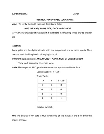
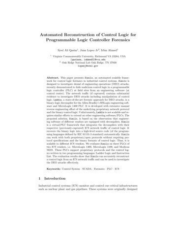
Control Logic Reconstruction for PLC ForensicsFig. 3: DEO Attack II: Crashing the decompiler running on Engineering software1) DEO Attack I. In DEO I (Figure 2), an attacker performs a man-in-themiddle between a target PLC and an engineering workstation (the computerrunning an engineering software). When the control engineer downloads a control logic program to a compromised PLC, the attacker intercepts the communications and infects this control logic by replacing some part of the code withmalicious logic before forwarding it to the PLC. Similarly, when the control engineer tries to upload the control logic from the PLC, the attacker interceptsthe traffic and replaces the infected logic with the original code. In this way, thecontrol engineer remains unaware of the malicious control logic running on thePLC.Consider the ladder logic program in Figure 1a, the timer controls the yellowlight in a traffic light signal. The attacker modifies the preset value from 6 secondsto 80 seconds when the program is downloaded to the PLC of the signal. Whena control engineer attempts to retrieve the program from the PLC, the attackerintercepts the traffic and change the preset back to its original value i.e., 6.2) DEO Attack II. DEO II is similar to the DEO 1 in that the attackerperforms a man-in-middle between the engineering workstation and PLC, intercepts the communication, and manipulate the traffic as it passes through theattacker’s machine. However, in DEO II (Figure 3), the attacker replaces theoriginal code with random (noise) data such as 0xFFFF. When an engineeringsoftware receives the malformed logic, it fails to decompile.2.3Challenges in DEO Forensic InvestigationFor a forensic investigation of DEO attacks, the network traffic (if captured) contains substantial evidence including manipulation of control logic. The challengeis to reconstruct and transform the binary control logic (in the traffic dump)into its high-level source code. Unfortunately, binary control-logic does not havea standard open format (such as Linux ELF) to allow a generic decompiler. ICSvendors define their binary control-logic representations. Often, each vendor hasmultiple binary representations across their different engineering software to program different types of PLCs.Recall that IEC 61131-3 standard defines five programming languages forPLCs (such as Structured Text, and Ladder Logic) [9]. An engineering softwareoften supports only one or two languages. Thus, binary logic must be transformed into their respective high-level languages for forensic investigation, mak-
Syed Ali Qasim et al.ing the transformation more challenging. Lastly, the engineering software andPLCs communicate using different ICS protocols that may be proprietary ormay use an open protocol with an embedded proprietary protocol layer. Thus,reconstruction of binary control logic from a network traffic capture requiresextensive manual reverse engineering of the proprietary protocols.The closest effort in this direction to develop forensic investigation capabilities for control logic is Laddis [16], which is a binary-logic decompiler forthe Allen-Bradleys RSLogix engineering software and MicroLogix PLC series.Laddis is developed with the manual reverse engineering of the PCCC protocoland the binary representation of the high-level ladder logic program written inRSLogix. Unfortunately, Laddis is not scalable and requires similar efforts toextend on other engineering software/PLCs.3Problem StatementGiven an ICS network traffic dump of a control logic, our goal is to reconstructand transform the binary control logic (in the traffic dump) into its high-levelsource code. Considering the challenges outlined in Section 2.3, a practical solution should address at least two basic requirements:Automation. The solution must be automated to achieve a high-level sourcecode of a low-level binary control logic in a network traffic without human intervention including reverse engineering of a proprietary ICS protocol and a binaryrepresentation of a high-level control logic.Scalability. The solution must be scalable to multiple vendor products including engineering software (used to create a control logic), proprietary ICSprotocols, and PLCs.44.1Similo - A virtual PLC FrameworkOverview of SimiloWe observe that engineering software of different vendors are equipped withdecompilers that can transform a binary control logic into a high-level languagesource-code. We propose to integrate a decompiler in engineering software with apreviously-captured network traffic dump of a control logic to obtain the sourcecode of the control logic. Our solution is Similo, an automated and scalablevirtual-PLC framework that does not require manual reverse engineering. Similoutilizes the upload function of an engineering software to achieve the integration.Upload function. The upload is a required functionality (used by control engineers) to retrieve a binary control logic from a PLC remotely, which furthertriggers a decompiler in engineering software to achieve high-level source codeof the control logic.Generally, when a control engineer runs the upload command in engineeringsoftware, it starts a series of request-response messages between a PLC andan engineering software such as session-establishment messages, echo messages,
Control Logic Reconstruction for PLC ForensicsFig. 4: Overview of Learning/Training phaseand control logic messages. Engineering software first establishes a session witha PLC and then, sends read-request messages to the PLC to read the memorylocations of a control logic. In response, PLC sends the data on the requestedmemory locations (i.e., control logic) to the engineering software in the payloadof response messages. After receiving an entire binary control logic, engineeringsoftware passes it to the decompiler to trigger decompilation process, which inturn produces the source code in a high-level language.Virtual-PLC framework. To develop Similo, we assess the communicationbehavior of the upload function of two engineering software, RSLogix 500 andSoMachine-Basic with three PLCs, Allen-Bradley’s MicroLogix 1400 and MicroLogix 1100, and Schneider Electric’s Modicon M221. We make two interesting observations that show that the communication behavior is deterministic:first, an engineering software always makes a small number of unique requeststo retrieve the control logic from a PLC; second, if we send an associated response message from a previous network dump as reply to a request messagefrom engineering software, the next request message from the software will besame as the next request message in the network traffic dump.Based on these observations, we design Similo using the upload function.Recall that engineering software uses the upload function to retrieve controllogic from a PLC memory. Similo on the other hand retrieves control logicfrom a network traffic (captured during the transfer of the logic). It consistsof a virtual-PLC that responds to the upload function queries using a previous network traffic dump of a control logic. It handles dynamic protocol fieldsin the request-response messages automatically, making it scalable to differentPLCs, proprietary protocols and engineering software. For this paper, we testSimilo successfully on three different PLCs (Micrologix 1400, MicroLogix 1100and Modicon M221), two ICS protocols (ENIP, and Modbus) and two engineering software (RsLogix, and SoMachineBasic).Similo consists of two phases: training, and testing. The training phase provides understanding of dynamic header fields of messages using benign pcap fileswhile the testing phase engages an engineering software to respond to the requestmessages using the response messages in a network traffic (under investigation)including updating the header fields.
Syed Ali Qasim et al.4.2Learning/Training PhaseFigure 4 presents an overview of the training phase, which consists pairing,comparison and grouping, and optimization steps for identifying dynamic headerfields in request-response messages.Pairing. Pairing is the first step to identify an instance of a message in a set oftwo benign pcap files from different sessions that contain same control logic. Weassume that the header values of dynamic fields change across multiple sessions.However, their contents (control logic) remain the same since same control logicis used on both pcap files. We use two properties of a message to find samemessage instance in the pcap files: 1) message length and 2) message contentsimilarity.Ideally, we have to compare each message of the first pcap file with all messages of the second pcap file to find the best match. However, we optimize thisapproach by finding a match with 85% threshold (based on our initial experiments) i.e if the length of two messages is same and the similarity is more than85%, they are considered same and paired together. In our experience, this approach decreases the time taken for learning significantly without affecting thefunctionality of Similo. Note that pairing is used for initial screening of pcapfiles and does not assume to achieve 100% accuracy for finding same messages.The results of pairing are further refined in later stages. Figure 4 show the pairing process, where Req (i,1) and Res (i,1) is a request response pair from pcap1and Req (i,2) and Res (i,2) is a pair from pcap2.Comparison and Grouping. After pairing similar messages, Similo performsdifferential analysis on each pair, i.e comparing two messages character by character and records the indices (i.e., locations of bytes) where the values are different. During our experiments, we found that the length of header fields vary indifferent request messages due to which the offsets of dynamic fields also vary.In order to tackle this, Similogroups messages based on length such that all themessages in one group will have the same header size and structure. There afterSimilofind the differences of all message pairs in one group which are furtherprocessed to get the dynamic fields.Optimization. In this process, the differences identified between the messagepairs in each group are compared with one another and only those indices areselected that are present in more than 50% of messages. Since the initial pairingis not 100% accurate, there is a chance that other than the dynamic headerfields, some paired messages may also have little differences in payload too. Sothe optimization process filters the differences present in payload. For exampleif the differential analysis of three message pairs of length X has resulted in thefollowing dynamic field indices: (0,1,4,9,19),(0,3,4,15),(1,3,4,22) the resultantwould be (0,1,3,4), which will represent the offsets of dynamic fields in all themessages in group X. The optimized indices are further divided in differentgroups based on the adjacency and each group represents one dynamic field suchas transaction ID, length etc. These dynamic fields might be incomplete/partiallyfilled but that problem is solved during the testing phase.
Control Logic Reconstruction for PLC ForensicsFig. 5: Overview of Testing phaseAfter these steps, Similo gets the indices of dynamic fields in all the requestresponse messages present in one set of pcap files. The same process is repeatedwith other pcap files and finally the results of all the files are again compared andanalyzed using the majority rule and the information and the resulting dynamicfields, referred to as Learning Phase Dynamic Fields (LPDF), are used in testingphase.4.3Testing PhaseFigure 5 shows an overview of the testing phase. After completing the trainingphase, Similo takes a target pcap file, extracts request and response messages,and then, stores them in database in the form of request and response pairs. Afterwards, it starts the communication server and waits for the message from theengineering software initiated by the upload function. Upon receiving a request,the communication server forwards it to the Identifier. The identifier performstwo tasks. First, it finds the same request message (based on content) in thedatabase. Second, it compares the two messages and identifies the dynamic fieldsbetween these two request messages. We call them training phase dynamic fields(TPDF).The identification is similar to pairing since it uses message length and content similarity. However, at this stage, we have information about the dynamicfields from the learning phase. Note that the dynamic fields are present in theheader and the later part contains the control logic. For every request messagewith the same length as of the new request message, instead of comparing thewhole message, the identifier only compares the part that lies beyond the lastdynamic field determined by learning phase.The grouping of messages based on length helps Similo in performing thelook up efficiently. The identifier selects the request message with highest similarity with a new request message. It then, passes the request along with therequest-response pair from the database to Reconstructor. Similarly, the testingphase dynamic fields are passed to Field analyzer.
Syed Ali Qasim et al.Fig. 6: Accumulation example of dynamic fields in learning and testing phasesField Analyzer. We know the location and tentative size of dynamic fields ina message, however we still have to ascertain the boundary of the fields. To findcomplete fields, field analyzer compares the dynamic fields from learning phasewith the dynamic fields from the testing phase. Specifically, if any dynamic fieldfrom the TPDF overlaps, is adjacent to, or is confined in any dynamic fieldfrom the LPDF, Field analyzer combines it with the dynamic field from learningphase otherwise it discards it. Figure 6 explains the working of Field Analyzer.In the first case two fields were identified in the testing phase i.e (2,3) and (9).Since (2,3) is overlapping one of the LPDF, it is combined with it resulting in(0,1,2,3) where as (9) is not overlapping, adjacent or confined in any of the LPDFso it is discarded. Similarly the second and third case explains the Adjacent andConfined scenarios.It is still possible that even after this combination some fields are partlyempty. That means the values at those indices remain same in both sessions,thus we do not need to change them for reconstructing the response message.The final dynamic fields are forwarded to Reconstructor.Reconstructor. It is the last component in Similo, which takes request-responsemessages from the target pcap and the dynamic field offsets from the Field analyzer. The dynamic fields in a target request message are mapped to its pairedresponse message. If the values are same, reconstructor changes the values of dynamic fields in the response message according to the values in the new requestmessage and forwards this message to the communication server. The communication server then sends this response message to the engineering software andwaits for next request and so on. This process finally makes the engineeringsoftware to recover the control logic from the network dump.5ImplementationWe have implemented Similo in python and used scapy [14] for network packetmanipulation. During the learning phase, Similo makes dictionaries from thepcap files. The request and response messages are filtered on the basis of IPaddress and port. The transport layer payloads of request and response messagesare converted to hex streams and used as keys and values.To calculate similarity, we use SequenceMatcher from difflib library [8]. Furthermore, Similo compares both sets of requests and response messages presentin each tuple, character by character and the differences are stored in a dictionary, where length of request message represents the key and value is a list of
Control Logic Reconstruction for PLC Forensicsarrays of differences generating from each comparison. These differences are laterprocessed to get the offsets of dynamic fields within a packet via Optimization.The optimization uses a majority rule to separate the protocol related dynamic fields from the rest. For each message type (based on length), it calculatesthe number of instances of each offset. If an offset appears in majority (morethan 50% or user defined threshold), it is considered as part of dynamic fieldand used in the testing phase, otherwise, it’s ignored.During our research, we found that generally, the PLCs have fixed portsfor communicating with the engineering software e.g Allen-Bradley MicroLogix1100 and 1400 use port 44818, Modicon M221 uses port 502. Thus, in the testingphase, using the socket library, Similo opens a server socket (communicationserver) using socket on the default ports of real PLCs and waits for messagefrom the engineering software. After getting a target pcap file from the user, itgenerates the database i.e dictionary using the method explained.The identifier is a search function that takes a request message from the serverReq (i,n) and iterates on the database keys to finds same request message withdifferent dynamic fields (req t). For this purpose, it uses the length and similarityof static fields. After finding same request from the target pcap Req(i,T), itcompares these two requests to find the differences. The Identifier then passesthe Req (i,n), Req (i,T) and Res (i,T) to the reconstructor and TPDF to theField analyzer.The field analyzer function takes two inputs: LPDF, and TPDF. It iteratesover both of them and if any TPDF fields are adjacent, overlap or one is confinedin the boundary of a LPDF, it combines the two, otherwise, it ignores the TPDF(Figure 6). The output of this function is an array of arrays containing dynamicfield offsets. Finally the Reconstructor function takes the Req(i,n), Req(i,T) andRes (i,T) from the Identifier and the final set of dynamic fields from the Fieldanalyzer. It maps the dynamic fields in Req (i,T) on Res (i,T) to check if thevalues of dynamic field in the request and response message are same. If it is true,it edits the Res (i,T) by changing the value of dynamic fields according to thenew request R(i,n) and forwards the new response message to the communicationserver, which then sends it to the engineering software.6EvaluationLab Setup. We evaluate Similo on three PLCs Allen-Bradley MicroLogix 1400Series B, Allen Bradley MicroLogix 1100 Series B, and Schneider Electric Modicon M221. The engineering softwares used for the first two PLC is RSLogix500 V9.2.01 and M221 is evaluated on SoMachine Basic v 1.6 and v 1.4. Bothprogramming software run on Windows 7 virtual machine (VM) and the virtualPLC runs on a VM with Ubuntu v 16.04. The engineering software, PLCs andvirtual-PLC all were connected via Ethernet.Experiment Methodology. A typical experiment includes capturing the network traffic when an engineering software uploads a control logic from a real
Syed Ali Qasim et al.Table 1: Dataset summary of Ladder logic programs for MicroLogix 1100File InformationRungInstructionFile# of Files Min Max Total Avg. Min Max Total Avgsize (KB)0-401621790 5.62 3482401541-60144441212121261-804863145 36.25 25 245 543 135.7581-10011313131337373737Total22252832-Table 2: Dataset summary of Ladder logic programs for MicroLogix 1400File InformationRungFile# ofMin Max Totalsize (KB) 528101-1201101010Total39379InstructionAvg. Min Max Total Avg4.71 110.33 422.57 2814151023-48276 13.1453344 38.88245 577 96.1663752262323231272-PLC. Similo uses the pcap files and communicates with the engineering software to recover the control logic. At the end, two programs are compared in theengineering software manually to find accuracy of the v
of the control logic in the tra c dump to an engineering software. This results in a correct reconstruction and transformation of a control logic into a source-code. We further recreate DEO attacks on these PLCs and engineering software and utilize Similo to investigate them successfully. 2 Background 2.1 Control Logic Programmable Logic .