Transcription
Programmable Digital-7 PlusPN 7531ONLINE PRODUCT REGISTRATION: Register your MSD product online. Registering your productwill help if there is ever a warranty issue with your product and helps the MSD R&D team createnew products that you ask for! Go to www.msdperformance.com/registration.Parts Included:1 - Ignition Control, PN 75311 - MSD Pro-Data CD Rom4 - Vibration Mounts & Screws1 - Shielded Cam Sync Harness1 - 9-Pin Computer HarnessAccessoriesHand Held Monitor, PN 7550Inductive Cam Sync Pickup Kit, PN 7555Non-Magnetic Cam Sync Pickup Kit,PN 2346Manual Launch RPM Control, PN 7551Digital Shift Light, PN 75421 - Mag Pickup Harness, PN 88601 - 12-Pin Harness1 - Coil Harness1 - Power Lead HarnessMAP Sensor, see page 9Replacement Harness, PN 8855Single Pole/Single Throw Relay, PN 8961Double Pole/Double Throw Relay, PN 8960WARNING: During installation, disconnect the battery cables. When disconnecting, always removethe Negative cable first and install it last.Note: Solid core spark plug wires cannot be used with an MSD Ignition Control.Important: When installing a Digital Series Ignition, timing will be affected, reset to your engine’sspecifications.OPERATIONDIGITAL OPERATIONThe MSD Programmable Digital-7 Plus uses a high speed RISC microcontroller to control the ignition’s outputwhile constantly analyzing the various inputs such as supply voltage, trigger signals and rpm. The high speedcontroller can make extremely quick compensations to the output voltage, multiple spark series, timing and rpmlimits while maintaining accurate timing signals to within /- 0.1 and /- 10 rpm. The circuits and controller ofthe ignition have been thoroughly debounced and suppressed to create protection against Electro MagneticInterference (EMI).CAPACITIVE DISCHARGEThe MSD features a capacitive discharge ignition design. The majority of stock ignition systems are inductive ignitions.In an inductive ignition, the coil must store energy and step up the supplied voltage to maximum strength betweeneach firing. At higher rpm, since there is less time to charge the coil to full capacity, the secondary voltage falls shortof reaching its maximum energy level which results in a loss of power or top end miss.The MSD Ignition features a capacitor which is quickly charged to 520 - 535 volts and stores its energy until theignition is triggered. With the CD design, the energy sent to the coil is always at maximum power even at high rpm.MSD WWW.MSDPERFORMANCE.COM (915)857-5200 FAX(915)857-3344
2INSTALLATION INSTRUCTIONSMULTIPLE SPARKSThe MSD produces full power multiple sparks for each firing of a plug. The number of multiple sparks that occurdecreases as rpm increases, however the spark series always lasts for 21 of crankshaft rotation. Above 3,300 rpmthere is simply not enough “time” to fire the spark plug more than once, so there is only one powerful spark.PROTECTIONThe MSD Programmable Digital-7 Plus has a built in reverse polarity protection circuit. This will protect the ignitionin the event of wrong connections. It will also shut off for protection from a surge in power. The ignition will stilloperate once the surge or polarity is corrected.LED INDICATORThere is an LED that monitors the status of the Ignition. The LED will verify trigger inputs and will flash troublecodes such as a Code 2-blinks for No Cam Sync or Code 3-blinks for Low Battery supply voltage.CAMSHAFT SYNCHRONIZATIONThis is used only in applications where the individual cylinder timing is going to be used. The 2-pin connectorwith a Light Blue and Light Green wire connects to a sensor that is used to synchronize or alert the Ignition as towhen the number one cylinder is going to be triggered. With this information, the Ignition knows which cylinderis being fired allowing for the individual cylinder timing capabilities. MSD offers two kits to use for sync signals:Universal Cam Sync Sensor, PN 2346 and a Fiber Optic Inductive Pickup Kit, PN 7555.WIRINGHeavyRedIgnition supply wire. Connects to battery positive ( ) terminal or battery junction.Note: Do not connect to the alternator.HeavyBlackIgnition supply Ground wire. Connect to battery negative (-) terminal or engine block.RedOn/Off switch wiring. Connects to a switched 12 volt source.Primary Coil LeadsOrangeConnects to the coil positive ( ) terminal. This is the only wire that makes contact tothe coil positive terminal.BlackConnects to the coil negative (-) terminal. This is the only wire that makes contact tothe coil negative terminal.WARNING: High voltage is present at the coil primary terminals. Do not touch the coil orconnect test equipment to the terminals while the engine is running or cranking.Trigger WiresViolet/Green2-PinMagnetic pickup, 2-pin connector. Plugs into an MSD Distributor or Crank Triggerpickup. Violet is positive, Green is negative. Note: When this connector is used, theWhite wire is not connected.WhiteTrigger input for electronic ignition amplifiers, an ECU’s trigger or points.Note: When this wire is used, the magnetic pickup wire is not connected.Tach OutputGrayMSDTach output. This wire will provide the same 12 volt square wave tach signal as thetach terminal on the side of the unit. WWW.MSDPERFORMANCE.COM (915)857-5200 FAX(915)857-3344
INSTALLATION INSTRUCTIONS3AccessoriesDark BlueThis wire activates the Launch Rev Limit and is the main reset wire for several features of theIgnition. When 12 volts are applied to this wire it will activate the Launch Rev Limit. It also resetsthe shift light and gear indicator to first gear. It also will select the Launch Retard value and Gear1 curve. When 12 volts is removed, the Launch Ramp begins as does the Gear 1 curve.When12 volts are applied the Slew Rate Rev limit will be disabled as well as the Timed Rev Limitcurve. When 12 volts are removed the Launch History begins recording.Light BlueBurnout Rev Limit. When 12 volts are applied the Burnout Rev Limit is active. This disables theAcquisition function and Slew Rate Rev Limits and overrides other rev limits. It also resets theAcquisition Record function.It is recommended to have this wire switched from an outside source, such as the crew chief beforethe burnout and while staging the car.Spool-UpLimitWhen the Dark Blue and Light Blue wires are applied to 12 volts at the same time, a fourth revlimit is activated. This limit is to spool up a turbo during the burnout. When both the Dark Blueand Light Blue RevLimit wires are at 12 volts then the Spool RevLimit is active.Retard Stage Wires or Gear SelectThese three wires can be used as Retard Stage Activation and/or as a gear select wire.PinkStep1 retard enabled with 12 volt input and above Step1 Rpm value and Gear 2 Select.VioletStep2 retard enabled with 12 volt input and above Step2 Rpm value and Gear 3 Select.TanStep3 retard enabled with 12 volt input and above Step3 Rpm value and Gear 4 Select.Note:When activated at the same time, these retard stages are added together. They are alsoadded with any Gear Retard Curve or Boost Retard values as well. Maximum retard is 30 .YellowShift Light output wire. It can handle up to 3 amps continuous to ground when enabled.Brown/White RPM/Time/Pressure switch output wire. It can switch up to 3 amps continuous to groundwhen enabled.Yellow/Yellow Output for data acquisition or fuel controls. Note, only two wires are used.3-Pin Connector, MAP SensorConnector Connects to an external MAP or gauge pressure sensor.Brown/Violet 5 volt supplyBrown/Yellow GroundDark BrownMap SignalCam SynchronizationFiber OpticThis input requires the PN 7555 Inductive Sync Pickup. When this input is used, the 2-pin connector is not. Note: If this input is not used, the plug or a cover should be installed.2-Pin ConnectorLt Blue/Lt GreenMSDThis 2-pin plug connects to Cam Sync Sensor, PN 2346, to indicate when cylinder numberone is firing. Note: When used, the fiber optic connector is not used and must be covered. WWW.MSDPERFORMANCE.COM (915)857-5200 FAX(915)857-3344
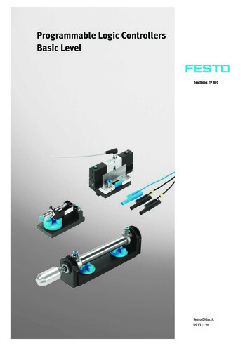
4INSTALLATION INSTRUCTIONSFigure 1 Wiring the Programmable Digital-7 Plus Ignition.PRO-DATA INSTALLATION OF THE PRO-DATA SOFTWARE1. Insert the installation CD Rom into the CD drive, wait up to 30 seconds, the CD will auto run, IFTHIS DOES NOT OCCUR:Locate and open the CD Drive.Double click on the autorun.exe file.2. Select “Click here to Install Version X.XX”.3. Once loaded, your monitor will have an MSD Pro-Data Plus X.XX logo. Accept the agreement.Drive the installation to your program files folder, press the enter key. The installation will complete,select OK.4. A window will be opened with two aliases, double-click on the MSD GraphView alias to launchthe software. In the GraphView window, drag down on file and open. This will display a listing ofdifferent part number folders. Open the 7531 folder and select your version. Double clicking theversion will launch the Pro-Data software for the Programmable Digital-7 Plus Ignition.SAVES AND TRANSFERSWhenever a change is made to a program, it either must be saved to a file in your PC or it needs tobe transferred to the ignition. You will notice that whenever you make a change to a program, thebullet next to the modified value will turn red. It will remain red until you save it to a file or to the MSD.There are two ways to save your files.MSD WWW.MSDPERFORMANCE.COM (915)857-5200 FAX(915)857-3344
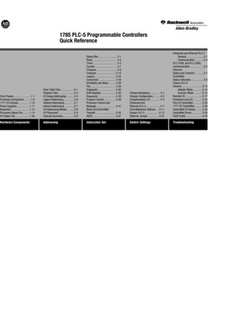
INSTALLATION INSTRUCTIONS5Save to MSD: This step will save any changes directly into the ignition. If you are only makingone or just a couple modifications this works well.Save to PC: This will save your changes to only show on the PC screen (indicated by a redbullet point next to any altered values). These modifications will not be active or saved untilyou save the file or transfer the information to the MSD.You can create numerous files on your PC and download them for testing purposes or by savingprograms you used at different races or test sessions.ACQUIRED INFORMATIONMONITORHISTORY TRACESSOFTWAREVERSIONHISTORY HREV LIMITMENUTREEBOOST CURVETACHGEAR TRACESTIMINGBOOSTGAUGEICMGEAR RETARDCURVESFigure 2 Pro-Data Screen and Program Windows.PROGRAMMABLE FEATURESThe following explains the programmable features of the PN 7531 Ignition. The features are listed in thesame order that they show on the Data Editor list in the software. Note that all of the retard amounts arecumulative and the maximum amount of retard is 30 . The gear curves are independent.STATSStat 1: This is only used with the Hand Held Monitors, PN 7550, PN 7553.MSD WWW.MSDPERFORMANCE.COM (915)857-5200 FAX(915)857-3344
6INSTALLATION INSTRUCTIONSREV LIMITSUp to four different rev limits can be programmed in 100 rpm increments.RevBurn: Burnout Rev Limit. This limit is activated when 12 volts are applied to the Light Bluewire. It is adjustable from 2,000 to 12,500 rpm. Note that the Slew Rev Limiter is disabled bythe Burnout Limit.RevLaunch: Launch Rev Limit. This limit is activated when 12 volts are applied to the DarkBlue wire. It is adjustable from 2,000 to 12,500 rpm.RevMax: Max Speed Rev Limit. This is the overrev limit and is active whenever the Launchand BurnOut limits are off.OutCam: Select either a Cam Sync output or a Rev Limiting output that can be used withMSD components that use rpm modules for the rev limit, or data acquisition units.AdjOff: This program enables an automatic compensating rev limiter that willcorrect trigger input offsets and variables. It can be turned On or Off.RPM: Adjustable in 100 rpm increments from 2,000 – 12,500.Spool-Up: This program gives turbo cars a fourth rev limit to help the engine spool boostpressure prior to the burnout. It is active when both the Light and Dark Blue wires are appliedto 12 volts at the same time. It is adjustable in 100 rpm increments from 2,000- 12,500. Defaultis 3,000 rpm.Note: See page 15 for information and examples on how to wire the rev limits.REVLIMIT CURVEThis program allows you to map an rpm limiting curve based on time. It is programmed in graph viewon the Rev Limit chart and is adjustable in 100 rpm increments down to 0.01 seconds for up to 12.5seconds.Pt 1: Adjust from the Rev Limit chart of graph view (up to 32 points).Time .00: Adjust from the Rev Limit chart of graph view.RPM: Adjust from the Rev Limit chart of graph view.RPM SLEWThis program provides an rpm limiting function based on a ratio between engine rpm and time. Theresult is a programmable rate of acceleration for each gear. You can program the rate at which theengine accelerates by selecting an rpm per second. If 3,000 rpm is selected, that means the enginewill be limited to 3,000 rpm per second. This is adjustable for each gear.Gear 1: The RPM Slew rate for each gear. Adjustable from 1-6.RPMSlew: The rpm amount per second, adjustable from 100 – 9,900 rpm per second in 100rpm increments. Note that this Slew rate is disabled when the Launch or Burnout rev limitsare active.Note: The Slew Rev Limiter is not recommended with distributor triggers. A crank trigger should be used.MARGINThe Slew Margin is a program to ensure very accurate rev limiting action especially when an engine accelerates quickly. There is a High and Low Margin value that ranges from 100-990 rpm.The Margins should be programmed close to the Slew depending on the engine’s accelerationMSD WWW.MSDPERFORMANCE.COM (915)857-5200 FAX(915)857-3344
INSTALLATION INSTRUCTIONS7capabilities. At lower rpm, there are less revolutions per second so the Margin should be set lower. Athigh rpm there are more combustion events taking place as well as more mechanical variables (suchas crank flex) so the high Margin should be set higher.Low: Default is 200 rpm.High: Default is 400 rpm.LAUNCH SLEWThis controls the status of the Slew Rev Limiting feature.SlewOff: Activates the Slew Rev Limiting feature. Default is Off.Inhibit: This feature allows you to inhibit the activation of the Slew for an adjustable length oftime after the launch. It is adjustable from .02 - 5 seconds in 20ms increments.TARGETHoldCnt: The number of cylinder counts that occur after a Slew rev limit is active before theSlew Target rpm is repositioned. The default is 10 which is typical for an engine in the 70008000 rpm range.Higher revving engines should use a higher Hold Count. A pro stock engine typically will beset around 11 or higher. The count is adjustable from 1-99 and is most effective in the 5-20range.LIMIT CNTThe Limit Count will set a maximum number of Rev Limits by the Slew Rate Rev Limiter. Adjustablefrom 0-500 maximum, in increments of 2.Note: Reviewing the Launch History will help set the Target and Margin settings.START RETARDProgram an amount of retard that will occur while the engine is cranking. This helps reduce the loadon the starter for easier cranking. It is adjustable from 0 - 25 in 1 increments. This is an automaticfeature and will enable below 500 rpm and will deactivate when the engine reaches above 800 rpm.Default is 10 .LAUNCH RETARDThis is the time based retard ramp. It can be programmed from 0 -15 in 0.1 increments and from0-2.5 seconds. When the Dark Blue Launch/Reset wire is connected to 12 volts, the retard value isactivated and is added to the retard sum. When 12 volts are removed from the Dark Blue wire, theretard value begins to ramp up to 0 over the programmed time. Once the time is over, the retard willnot be activated again.STEP RETARDSThere are three step retards that are controlled through three corresponding activation wires or throughrpm. They can also have an rpm point that the engine must reach before the retard becomes active.(A minimum rpm can also be programmed that must be reached before a step becomes active.) Atime based ramp can be programmed to gradually bring the retard to its full On amount, or to rampthe retard amount out (back to no retard) from its setting.Step 1 – PinkStep 2 – VioletStep 3 – TanNote: These wires can also be used as Gear Select Indicators. See page 9.Activation through Wiring: Each step is activated when 12 volts are applied to itscorresponding wire. When the steps are enabled at the same time the retard amounts areMSD WWW.MSDPERFORMANCE.COM (915)857-5200 FAX(915)857-3344
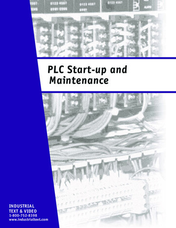
8INSTALLATION INSTRUCTIONSadded together. The maximum retard allowed by the Ignition is a total of 30 (including otherretard amounts from a launch, boost or gear retard).Activation through RPM: Each step retard can also be activated through rpm. In order to achievethis, 12 volts must still be applied to the corresponding step retard, and an rpm value must beselected from the Step RPM menu. When 12 volts are applied, the retard will not activate untilthe rpm value is reached. Note that the retard will remain active above this rpm, even when otherstages are activated. It will deactivate when the rpm drops below the set amount.Note: If you prefer to activate the step retards through the activation wires and not rpm, then the rpmvalue in each of the desired step menus must be set to 800 rpm.Step Retard Off Delay: This feature will set a time based delay to deactivate the step retards.This is designed to keep the timing retarded to clear the engine of any nitrous oxide prior todeactivating the retard. It is adjustable from 0 – 2.5 seconds and the default is 0.5 second.Step Retard Ramp: Each retard step can be ramped to and from its full retard amount over atime based program (Figure 3). It is adjustable from 0-2.5 seconds in 0.01 second increments.Default is 0 .TIMERPM: The minimum engine rpmthat must be reached before astep retard is activated.On: The amount of time it takesfor the step retard to reach itsRetard Degree. Allows a gradualramp On time to reach the RetardDegree. User adjustable from0.00 to 2.50 sec. (0.01 secincrements).Off: The amount of time it takesfor the step to retard to reach NOretard. Allows a gradual ramp Offtime to reach NO Retard. Useradjustable from 0.00 to 2.50 sec.(0.01 sec increments).Deg: The amount of retard.ONOFFFULL RETARDOn and Off Retard Step, NoRampingRAMPEDOFFONFULL RETARDRETARDRamping the Retard OnMOMENTARY KILLThis program will provide a way to momentarilyshut off the ignition output. This can be usefulin some applications to stop the ignition outputduring a shift. When the Kill circuit is selectedOn, the Tan third stage retard activation wirewill be used to kill the ignition output when itis connected to 12 volts. Once selected as theKill program, the Tan wire cannot be used asa retard step.ONRAMPEDOFFFULL RETARDRamping the Retard OffRAMPEDONRAMPEDOFFFULL RETARDRamping the Retard Onand OffFigure 3 Different Retard Activation Options.MSD WWW.MSDPERFORMANCE.COM (915)857-5200 FAX(915)857-3344
INSTALLATION INSTRUCTIONS9GEAR SELECTThe Three Step Retard wires, Pink (1), Violet (2) and Tan (3) can also be wired to indicate the firstthree gear changes to the ignition control. When selected from the Step Wire menu, the ignition willknow that the car is in second gear when 12 volts are applied to the Pink wire, third for the Violet andfourth when the Tan wire is applied to 12 volts. By using this feature, if you lift off the throttle and getback on it, the ignition will not count it as a gear change.Note: When selected, this feature overrides the RPM Drop Gear Select values.This is a sequenced series meaning Tan (3) will not become active until it sees 12 volts on Pink (1),and Violet (2). This way, 12 volts do not need to be removed from each wire before the following gearis selected.Note: Five and six speed transmissions will have to use the RPM Drop functions for gears 5 - 6.GEAR RETARDSThis program provides the ability to create a run curve for each gear. Up to six different curves canbe programmed from 800 – 12,500 rpm in 0.1 increments for every 100 rpm. You can program up to32 different points on each Gear Map. Also, all of these points are interpolated every millisecond tocreate a smooth (no steps) curve.The number of gears is adjustable under the SHIFT menu, as well as the
the shift light and gear indicator to first gear. It also will select the Launch Retard value and Gear . a fourth rev limit is activated. This limit is to spool up a turbo during the burnout. When both the Dark Blue . INSTALLATION OF THE PRO-DATA SOFTWARE 1. Insert the installation CD