Transcription
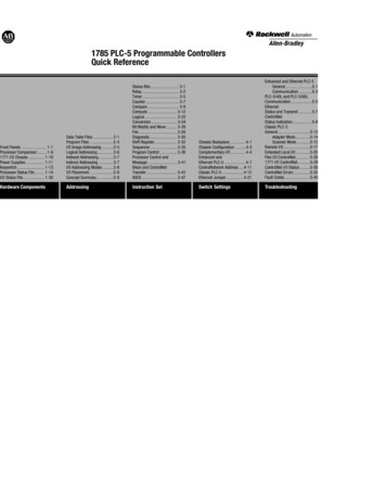
1785 PLC-5 Programmable ControllersQuick ReferenceFront Panels . 1-1Processor Comparison . 1-61771 I/O Chassis . 1-10Power Supplies. 1-11Keyswitch. 1-13Processor Status File . 1-14I/O Status File . 1-30Data Table Files .2-1Program Files .2-4I/O Image Addressing .2-5Logical Addressing.2-6Indexed Addressing.2-7Indirect Addressing .2-7I/O Addressing Modes .2-8I/O Placement .2-8Concept Summary.2-9Status Bits. 3-1Relay. 3-2Timer . 3-5Counter . 3-7Compare . 3-9Compute . 3-12Logical . 3-22Conversion . 3-24Bit Modify and Move. 3-26File . 3-28Diagnostic . 3-30Shift Register. 3-32Sequencer . 3-35Program Control . 3-36Processor Control andMessage . 3-41Block and ControlNetTransfer . 3-43ASCII . 3-47Chassis Backplane. 4-1Chassis Configuration . 4-3Complementary I/O . 4-4Enhanced andEthernet PLC-5 . 4-7ControlNetwork Address . 4-11Classic PLC-5 . 4-12Ethernet Jumper . 4-21Enhanced and Ethernet PLC-5General .5-1Communication .5-3PLC-5/40L and PLC-5/60LCommunication .5-5EthernetStatus and Transmit .5-7ControlNetStatus Indicators .5-8Classic PLC-5General .5-12Adapter Mode .5-14Scanner Mode.5-15Remote I/O .5-17Extended Local I/O .5-25Flex I/O ControlNet .5-281771 I/O ControlNet.5-29ControlNet I/O Status.5-30ControlNet Errors.5-35Fault Codes .5-45Hardware ComponentsAddressingInstruction SetSwitch SettingsTroubleshooting
Using this ManualThis Quick Reference provides information frequently needed for using and maintaining your Allen-BradleyPLC-5 processor.It is intended for reference purposes only, and not as the sole source of information.For more specific information on any topic in this Quick Reference, see: Enhanced and Ethernet PLC-5 Family Programmable Controllers User Manual, publication 1785-6.5.12 Classic PLC-5 User Manual, publication 1785-6.2.1 ControlNet PLC-5 Programmable Controllers Phase 1.5 User Manual, publication 1785-6.5.22Important User InformationBecause of the variety of uses for the products described in this publication, those responsible for the applicationand use of this control equipment must satisfy themselves that all necessary steps have been taken to assure thateach application and use meets all performance and safety requirements, including any applicable laws,regulations, codes and standards.The illustrations, charts, sample programs and layout examples shown in this guide are intended solely forpurposes of example. Since there are many variables and requirements associated with any particular installation,Allen-Bradley does not assume responsibility or liability (to include intellectual property liability) for actual usebased upon the examples shown in this publication.
The Safety Guidelines for the Application, Installation, and Maintenance of Solid State Control, publicationSGI-1.1 (available from your local Allen-Bradley office), describes some important differences betweensolid-state equipment and electromechanical devices which should be taken into consideration when applyingproducts such as those described in this publication.Reproduction of the contents of this copyrighted publication, in whole or in part, without written permission ofAllen-Bradley Company, Inc. is prohibited.Summary of ChangesIn this release of the PLC-5 Quick Reference, we have altered the way we reference software documentation.Rather than show specific screens and key sequences which may vary according to the software package youare using, we refer you instead to the programming software documentation that accompanies your particularsoftware package. Of course, we still provide the essential reference information you need to quickly accomplishyour tasks, but if you have specific questions about software procedures, you should refer to your programmingsoftware documentation set.To help you find new information, we included change bars as shown to the left of this paragraph.
ConventionsThe table below describes the naming conventions used in this manual:This name:Represents these processors:EnhancedPLC-5/11 PLC-5/40 PLC-5/20 PLC-5/60 PLC-5/30 PLC5/80 PLC-5/40L PLC-5/60L EthernetPLC-5/20E PLC-5/40E PLC5/80E ControlNetPhase 1.5PLC-5/20C15 5/40C15 5/80C15 ClassicPLC-5/10 PLC-5/15 PLC-5/12 PLC-5/25 You see this symbol in the lower right-hand corner of the page when information is continued on the next page. 1999 Rockwell AutomationPLC, PLC-2, PLC-3, PLC-5, PLC-5/10, PLC-5/11, PLC-5/12, PLC-5/15, PLC-5/20, PLC-5/25, PLC-5/30, PLC-5/40, PLC-5/40L, PLC-5/60, PLC-5/60L, PLC-5/80, PLC-5/20E, PLC-5/40E, PLC-5/80E, PLC-5/250,PLC-5/20C, PLC-5/40C, PLC-5/80C, Ethernet, and DH are trademarks of Rockwell Automation.
Front Panel – EnhancedPLC-5 ProcessorsPLC-5/11 ProcessorPLC-5/20 ProcessorIndicators:Battery (red)Processor RUN/FAULT (green/red)Force (amber)Channel 0 communicationstatus (green)KeyswitchInstall memorymodule hereChannel 0 - on-boardserial portChannel 1A statusindicator (green/red)Connect programming terminalhere when channel 1A is configuredfor DH communicationsChannel 1A communication portHardware ComponentsFront Panel1-1Battery holderChannel 1B statusindicator (green/red)Channel 1Afixed DH portChannel 1Bcommunication port
Hardware ComponentsFront Panel1-2PLC-5/30, -5/40, -5/60,-5/80 ProcessorKeyswitchPLC-5/40L, -5/60L ProcessorChannel 2Bstatus indicator(green/red)Channel 2A statusindicator (green/red)Channel 2 statusindicator (green/red)Connect programming terminal herewhen channel 2A is configured forDH communicationsChannel 2extended-local I/Ocommunication portChannel 2A communication portChannel 2B communication portIndicators:Battery (red)Processor RUN/FAULT (green/red)Force (amber)Communication ACTIVE/FAULTstatus (green/red)Channel 0 - on-boardserial portChannel 1Bstatus indicator(green/red)Channel 1A statusindicator (green/red)Connect programming terminal herewhen channel 1A is configured forDH communicationsLabels to write informationabout the channelcommunication mode,station addresses, etc.Channel 1A communication portChannel 1B communication portInstall memorymodule hereBattery holderThe PLC-5/30 processor has 2 communication ports and 1 serial port
Front Panel – EthernetPLC-5 ProcessorsPLC-5/40E, -5/80E ProcessorPLC-5/20E ProcessorIndicators:KeyswitchChannel 2 Ethernetstatus indicatorsChannel 2Battery (red)Processor RUN/FAULT (green/red)Force (amber)Channel 0 communicationstatus (green)Connect programmingterminal hereChannel 1AKeyswitchChannel 2 Ethernetstatus indicatorsChannel 2Install memorymodule hereChannel 0 - on-boardserial portChannel 1A statusindicator (green/red)Indicators:Channel 1B statusindicator (green/red)Connect programmingterminal hereChannel 1AChannel 1BChannel 1BBattery holderHardware ComponentsFront Panel1-3CommunicationACTIVE/FAULT (green/red)Channel 0 - on-boardserial portChannel 1A statusindicator (green/red)Battery holderBattery (red)Force (amber)Processor RUN/FAULT(green/red)Channel 1B statusindicator (green/red)Labels to write informationabout the channelcommunication mode,station addresses, etc.Install memorymodule here
Hardware ComponentsFront Panel1-4Front Panel – ControlNet PLC-5 ProcessorsPLC-5/20C15 ProcessorPLC-5/40C15, -5/80C15 ProcessorBatteryKeyswitchI/O Status IndicatorChannel 2 Status IndicatorsNetwork Access PortProcessor RUN/FAULTForceChannel 0 CommunicationACTIVE/FAULTBatteryKeyswitchI/O Status IndicatorChannel 2 Status IndicatorsNetwork Access PortChannel 2Channel 2Processor RUN/FAULTForceChannel 0 CommunicationACTIVE/FAULTChannel 0 - on-board serial portMemory Module SpaceChannel 1 Status IndicatorsChannel 0DH Programming TerminalConnection to Channel 1AChannel 1 Status IndicatorsDH Programming TerminalConnection to Channel 1AChannel 1AControlNet PLC-5 ProcessorsPhaseCatalog Number1.0/1.251.51785L20C, -L40C, -L80C1785L20C15, -L40C15, -L80C15Channel 1AMemory Module SpaceBattery HolderChannel 1BChannel 1BBattery Holder
Hardware ComponentsFront Panel – ClassicPLC-5 ProcessorsPLC-5/10 ProcessorDH communicationindicator ACTIVE/FAULT(green/red)PLC-5/12, -5/15, -5/25 ProcessorIndicators:REM I/O indicatorACTIVE/FAULT(green/red)KeyswitchBattery (red)Processor RUN/FAULT (green/red)Force (amber)PROGAdapter indicator(green)Battery holderWrite the DH network stationnumber on this labelConnect programmingterminal hereConnect DH link hereConnect remoteI/O link here12373Hardware ComponentsFront Panel1-5
Hardware ComponentsProcessor Comparison1-6Comparison Chart forPLC-5 Family ProcessorsProcessorMemory(Words)LocalChassisRemote Chassis(I/O Racks)I/O CapacityCommunicationPLC-5/106K1 residentnone128 (8-pt) 1, 256 (16-pt) 1, 512 (32-pt) 1DH linkPLC-5/126K1 residentnone128 (8-pt) 1, 256 (16-pt) 1, 512 (32-pt) 1adapter, DH linkPLC-5/156K1 resident(expands to14K)12(3 I/O racks) 512 1 512 inputs and 512 outputs using 16- or32-pt modules 2adapter/remote I/O scanner, DH linkPLC-5/2513K1 resident(expands to21K)28(7 I/O racks) 1024 1 1024 inputs and 1024 outputs using 16or 32-pt modules 2adapter/remote I/O scanner, DH linkPLC-5/118K4 256 (8-pt), 384 (16-pt), or 512 (16-pt) 1(1 I/O rack) 512(16-pt) or 768 (32-pt) 2rack must beaddressed as rack3121 resident 1 channel (remote I/O scanner, adapter, DH link) 1 RS-232, RS-422, RS-423 serial portAny mix of I/OMaximum I/O possible using 16-pt modules with 2-slot addressing or 32-pt modules with 1-slot addressing. Modules must alternate input/output in the chassis slots.
PLC-5 comparison chart continued.ProcessorMemory(Words)LocalChassisRemote Chassis(I/O Racks)I/O CapacityCommunicationPLC-5/2016K1 resident12(3 I/O racks) 512 1 512 inputs and 512 outputs using 16- or32-pt modulesPLC-5/20E16K1 resident12(3 I/O racks) 512 1 512 inputs and 512 outputs using 16- or32-pt modulesPLC-5/20C1516K1 resident12 (3 I/O racks) 512 1 512 inputs and 512 outputs using 16- or32-pt modulesPLC-5/3032K1 resident28(7 I/O racks) 1024 1 1024 inputs and 1024 outputs using16or 32-pt modules 1Any mix of I/OHardware ComponentsProcessor Comparison1-71 channel (remote I/O scanner, adapter, DH link)1 channel DH link1 RS-232, RS-422, RS-423 serial port1 channel (remote I/O scanner, adapter, DH link)1 channel DH link1 RS-232, RS-422, RS-423 serial port1 channel Ethernet1 channel (remote I/O scanner, adapter, DH link)1 channel DH link1 RS-232, RS-422, RS-423 serial portControlNet2 channels (remote I/O scanner, adapter, DH link)1 RS-232, RS-422, RS-423 serial port
Hardware ComponentsProcessor Comparison1-8PLC-5 comparison chart continued.ProcessorMemory(Words)LocalChassisRemote Chassis(I/O Racks)I/O CapacityCommunicationPLC-5/4048K31 resident60 2(15 I/O racks) 2048 1 2048 inputs and 2048 outputs using 16or 32-pt modules 4 channels (remote I/O scanner, adapter, DH link) 1 RS-232, RS-422, RS-423 serial portPLC-5/40L48K31 resident up 60 2to 16(15 I/O racks)extended 2048 1 2048 inputs and 2048 outputs using 16or 32-pt modulesPLC-5/40E48K360(15 I/O racks) 2048 1 2048 inputs and 2048 outputs using 16or 32-pt modules2 channels (remote I/O scanner, adapter, DH link)1 RS-232, RS-422, RS-423 serial port1 channel extended local I/O scanner2 channels (remote I/O scanner, adapter, DH link)1 RS-232, RS-422, RS-423 serial port1 channel EthernetPLC-5/40C1548K31 resident(16 rackaddressingcapability)1 resident 6015 I/O racks 2048 1 2048 inputs and 2048 outputs using 16or 32-pt modulesPLC-5/60 364K1 resident92 2(23 I/O racks) 3072 1 3072 inputs and 3072 outputs using 16or 32-pt modules 2 channels (remote I/O scanner, adapter, DH link)1 RS-232, RS-422, RS-423 serial port1 channel ControlNet4 channels (remote I/O scanner, adapter, DH link)1 RS-232, RS-422, RS-423 serial port123Any mix of I/OMaximum of 32 physical devices/channelMaximum of 57K words per program file and 32K words per data table file
PLC-5 comparison chart 60L 364KPLC-5/80 3.4I/O CapacityCommunication1 resident up 64 2to 16(23 I/O racks)extended 3072 1 3072 inputs and 3072 outputs using16or 32-pt modules100K1 resident92 2(23 I/O racks) 3072 1 3072 inputs and 3072 outputs using 16or 32-pt modules 2 channels (remote I/O scanner, adapter, DH link)1 RS-232, RS-422, RS-423 serial port1 channel extended local I/O scanner4 channels (remote I/O scanner, adapter, DH link)1 RS-232, RS-422, RS-423 serial portPLC-5/80E 3,4100K1 resident92 2(23 I/O racks) 3072 1 3072 inputs and 3072 outputs using 16or 32-pt modulesPLC-5/80C15 3.4100K1 resident92 2(23 I/O racks) 3072 1 3072 inputs and 3072 outputs using 16or 32-pt modules 2 channels (remote I/O scanner, adapter, DH link)1 RS-232, RS-422, RS-423 serial port1 channel Ethernet2 channels (remote I/O scanner, adapter, DH link)1 RS-232, RS-422, RS-423 serial port1 channel ControlNet1234Remote Chassis(I/O Racks)Any mix of I/OMaximum of 32 physical devices/channelMaximum of 57K words per program file and 32K words per data table fileMaximum of 64K words total data table spacePLC-5 ControlNet Processors - Maximum I/O Ma
Hardware Components Front Panel 1-2 PLC-5/30, -5/40, -5/60,-5/80 Processor PLC-5/40L, -5/60L Processor Keyswitch Battery holder Channel 2A status indicator (green/red) Connect programming terminal here when channel 2A is configured for DH communications Channel 2A communication port Channel 2B communication port Channel 1A status indicator (green/red)File Size: 769KBPage Count: 172
