Transcription
Programmable Logic ControllersBasic LevelTextbook TP 301Festo Didactic093311 en093311 cover textbook tp301 en.indd 113.04.2005 13:44:12
B-IIAuthorised applications and liabilityThe Learning System for Automation and Technology has been developed and prepared exclusively for training in the field of automation. Thetraining organization and/or trainee shall ensure that the safety precautions described in the accompanying Technical documentation are fullyobserved.Festo Didactic hereby excludes any liability for injury to trainees, to thetraining organization and/or to third parties occurring as a result of theuse or application of the station outside of a pure training situation, unless caused by premeditation or gross negligence on the part of FestoDidactic.Order s:Authors:093311SPS LB GSD.LB-TP301–1-GB08/200228.08.2002, OCKER IngenieurbüroD. Schwarzenberger, OCKER IngenieurbüroR. Bliesener, F.Ebel, C.Löffler, B. Plagemann,H.Regber, E.v.Terzi, A. Winter Copyright by Festo Didactic GmbH & Co., D-73770 Denkendorf 2002The copying, distribution and utilization of this document as well as thecommunication of its contents to others without expressed authorizationis prohibited. Offenders will be held liable for the payment of damages.All rights reserved, in particular the right to carry out patent, utility modelor ornamental design registrations.Parts of this training documentation may be duplicated, solely for trainingpurposes, by persons authorised in this sense.TP301 Festo Didactic
B-IIIPrefaceThe programmable logic controller represents a key factor in industrialautomation. Its use permits flexible adaptation to varying processes aswell as rapid fault finding and error elimination.This textbook explains the design of a programmable logic controller andits interaction with peripherals.One of the main focal points of the textbook deals with the new international standard for PLC programming, the EN 61131-3 (IEC-61131-3).This standard takes into account expansions and developments, forwhich no standardised language elements existed hitherto.The aim of this new standard is to standardise the design, functionalityand the programming of a PLC in such a way as to enable the user toeasily operate with different systems.In the interest of continual further improvement, all readers of this bookare invited to make contributions by way suggestions, ideas and constructive criticism.August 2002TP301 Festo DidacticThe authors
B-IVTP301 Festo Didactic
B-VTable of ContentsChapter 1 Automating with a PLCB-11.1IntroductionB-11.2Areas of application of a PLCB-21.3Basic design of a PLCB-51.4The new PLC standard EN 61131 (IEC 61131)B-8Chapter 2 FundamentalsB-112.1The decimal number systemB-112.2The binary number systemB-112.3The BCD codeB-132.4The hexadecimal number systemB-132.5Signed binary numbersB-142.6Real numbersB-142.7Generation of binary and digital signalsB-15Chapter 3 Boolean operationsB-193.1Basic logic functionsB-193.2Further logic operationsB-233.3Establishing switching functionsB-253.4Simplification of logic functionsB-283.5Karnaugh-Veitch diagramB-30TP301 Festo Didactic
B-VIChapter 4 Design and mode of operation of a PLCB-334.1Structure of a PLCB-334.2Central control unit of a PLCB-354.3Function mode of a PLCB-374.4Application program memoryB-394.5Input moduleB-414.6Output moduleB-434.7Programming device/Personal computerB-45Chapter 5 Programming of a PLCB-475.1Systematic solution findingB-475.2EN 61131-3 (IEC 61131-3) structuring resourcesB-505.3Programming languagesB-54Chapter 6 Common elements of programming languagesB-576.1Resources of a PLCB-576.2Variables and data typesB-606.3ProgramB-70Chapter 7 Function block diagramB-857.1Elements of function block diagramB-857.2Evaluation of networksB-857.3Loop structuresB-87Chapter 8 Ladder diagramB-898.1Elements of ladder diagramB-898.2Functions and function blocksB-928.3Evaluation of current rungsB-93TP301 Festo Didactic
B-VIIChapter 9 Instruction tions and function blocksB-97Chapter 10 Structured Selection statementsB-10310.4Iteration statementsB-106Chapter 11 Sequential function chartB-11111.1IntroductionB-11111.2Elements of sequential function ampleB-135Chapter 12 Logic control systemsB-13912.1What is a logic control systemB-13912.2Logic control systems without latching propertiesB-13912.3Logic control systems with memory functionB-14512.4Edge evaluationB-148Chapter 13 TimersB-15313.1IntroductionB-15313.2Pulse timerB-15413.3Switch-on signal delayB-15613.4Switch-off signal delayB-158TP301 Festo Didactic
B-VIIIChapter 14 CounterB-16114.1Counter functionsB-16114.2Incremental counterB-16114.3Decremental counterB-16514.4Incremental/decremental counterB-167Chapter 15 Sequence control systemsB-16915.1What is a sequence control systemB-16915.2Function chart to IEC 60848B-169Chapter 16 Commissioning andoperational safety of a PLCB-17516.1CommissioningB-17516.2Operational safety of a PLCB-177Chapter 17 CommunicationB-18317.1The need for communicationB-18317.2Data ion in the field areaB-185ABibliography of illustrationsB-187BBibliography of literatureB-189CGuidelines and 01 Festo Didactic
B-1Chapter 1The PLC in automation technology1.1 IntroductionThe first Programmable Logic Controller (PLC) was developed by agroup of engineers at General Motors in 1968, when the company werelooking for an alternative to replace complex relay control systems.The new control system had to meet the following requirements: Simple programming Program changes without system intervention(no internal rewiring) Smaller, cheaper and more reliable than corresponding relay controlsystems Simple, low cost maintenanceSubsequent development resulted in a system, which enabled the simple connection of binary signals. The requirements as to how these signals were to be connected were specified in the control program. Withthe new systems it became possible for the first time to plot signals on ascreen and to file these in electronic memories.Since then, three decades have passed, during which the enormousprogress made in the development of microelectronics did not stop shortof programmable logic controllers. For instance, even if program optimisation and thus a reduction of required memory capacity initially still represented an important key task for the programmer, nowadays this ishardly of any significance.Moreover, the range of functions has grown considerably. 15 years ago,process visualisation, analogue processing or even the use of a PLC asa controller, were considered as Utopian. Nowadays, the support ofthese functions forms an integral part of many PLCs.The following pages in this introductory chapter outline the basic designof a PLC together with the currently most important tasks and applications.TP301 Festo Didactic
B-2Chapter 11.2 Areas of application of a PLCEvery system or machine has a controller. Depending on the type oftechnology used, controllers can be divided into pneumatic, hydraulic,electrical and electronic controllers. Frequently, a combination of different technologies is used. Furthermore, differentiation is made betweenhard-wired programmable (e.g. wiring of electro-mechanical or electroniccomponents) and programmable logic controllers. The first is used primarily in cases, where any reprogramming by the user is out of thequestion and the job size warrants the development of a special controller. Typical applications for such controllers can be found in automaticwashing machines, video cameras, and cars.However, if the job size does not warrant the development of a specialcontroller or if the user is to have the facility of making simple or independent program changes, or of setting timers and counters, then theuse of a universal controller, where the program is written to an electronic memory, is the preferred option. The PLC represents such a universal controller. It can be used for different applications and, via theprogram installed in its memory, provides the user with a simple meansof changing, extending and optimising control processes.TP301 Festo Didactic
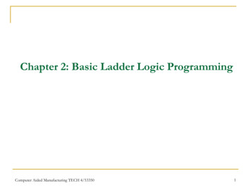
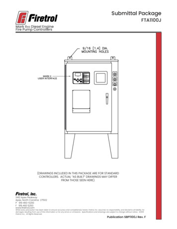
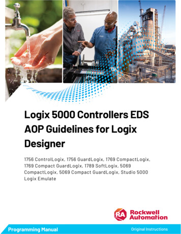
B-3Chapter 1Fig. B1.1:Example of aPLC applicationThe original task of a PLC involved the interconnection of input signalsaccording to a specified program and, if "true", to switch the corresponding output. Boolean algebra forms the mathematical basis for this operation, which recognises precisely two defined statuses of one variable: "0"and "1" (see also chapter 3). Accordingly, an output can only assumethese two statuses. For instance, a connected motor could therefore beeither switched on or off, i.e. controlled.This function has coined the name PLC: Programmable logic controller, i.e. the input/output behaviour is similar to that of an electromagnetic relay or pneumatic switching valve controller; the program isstored in an electronic memory.However, the tasks of a PLC have rapidly multiplied: Timer and counterfunctions, memory setting and resetting, mathematical computing operations all represent functions, which can be executed by practically any oftoday’s PLCs.TP301 Festo Didactic
B-4Chapter 1The demands to be met by PLC’s continued to grow in line with theirrapidly spreading usage and the development in automation technology.Visualisation, i.e. the representation of machine statuses such as thecontrol program being executed, via display or monitor. Also controlling,i.e. the facility to intervene in control processes or, alternatively, to makesuch intervention by unauthorised persons impossible. Very soon, it alsobecame necessary to interconnect and harmonise individual systemscontrolled via PLC by means of automation technology. Hence a mastercomputer facilitates the means to issue higher-level commands for program processing to several PLC systemsThe networking of several PLCs as well as that of a PLC and mastercomputer is effected via special communication interfaces. To this effect,many of the more recent PLCs are compatible with open, standardisedbus systems, such as Profibus to EN 50170. Thanks to the enormouslyincreased performance capacity of advanced PLCs, these can even directly assume the function of a master computer.At the end of the seventies, binary inputs and outputs were finally expanded with the addition of analogue inputs and outputs, since many oftoday’s technical applications require analogue processing (force measurement, speed setting, servo-pneumatic positioning systems). At thesame time, the acquisition or output of analogue signals permits an actual/setpoint value comparison and as a result the realisation of automatic control engineering functions, a task, which widely exceeds thescope suggested by the name (programmable logic controller).The PLCs currently on offer in the market place have been adapted tocustomer requirements to such an extent that it has become possible topurchase an eminently suitable PLC for virtually any application. Assuch, miniature PLCs are now available with a minimum number of inputs/outputs starting from just a few hundred Pounds. Also available arelarger PLCs with 28 or 256 inputs/outputs.Many PLCs can be expanded by means of additional input/output, analogue, positioning and communication modules. Special PLCs are available for safety technology, shipping or mining tasks. Yet further PLCsare able to process several programs simultaneously – (multitasking).Finally, PLCs are coupled with other automation components, thus creating considerably wider areas of application.TP301 Festo Didactic
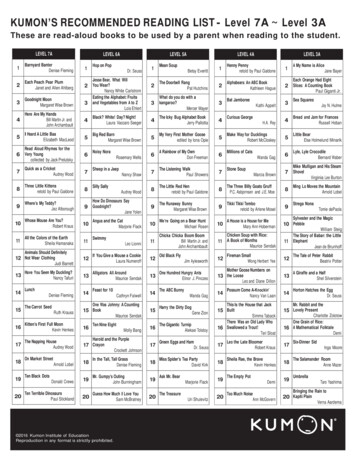
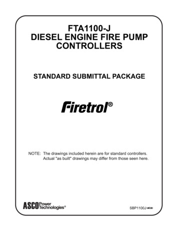
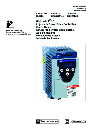
B-5Chapter 1Fig. B1.2:Example of a PLC:Festo IPC PS1 Professional1.3 Basic design of a PLCThe term ’programmable logic controller’ is defined as follows byEN 61131-1 (IEC 61131-1):“ A digitally operating electronic system, designed for use in an industrialenvironment, which uses a programmable memory for the internal storage of user-oriented instructions for implementing specific functionssuch as logic, sequencing, timing, counting and arithmetic, to control,through digital or analogue inputs and outputs, various types of machines or processes.Both the PC and its associated peripherals are designed so that theycan be easily integrated into an industrial control system and easily usedin all their intended functions."A programmable logic controller is therefore nothing more than a computer, tailored specifically for certain control tasks.TP301 Festo Didactic
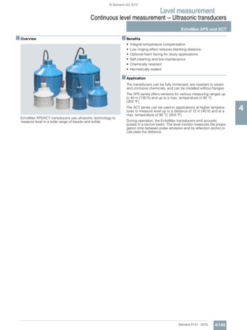
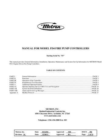
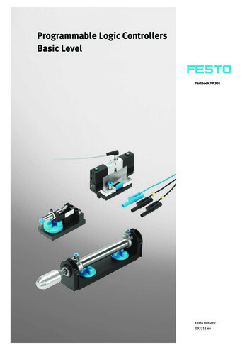
B-6Chapter 1Fig. B1.3 illustrates the system components of a PLC.Fig. B1.3:System componentsof a PLCPLC-programInput moduleSensorsCentral control unitOutput moduleActuatorsThe function of an input module is to convert incoming signals into signals, which can be processed by the PLC, and to pass these to the central control unit. The reverse task is performed by an output module. Thisconverts the PLC signal into signals suitable for the actuators.The actual processing of the signals is effected in the central control unitin accordance with the program stored in the memory.The program of a PLC can be created in various ways: via assemblertype commands in ’statement list’, in higher-level, problem-oriented languages such as structured text or in the form of a flow chart such asrepresented by a sequential function chart. In Europe, the use of function block diagrams based on function charts with graphic symbols forlogic gates is widely used. In America, the ’ladder diagram’ is the preferred language by users.Depending on how the central control unit is connected to the input andoutput modules, differentiation can be made between compact PLCs(input module, central control unit and output module in one housing) ormodular PLCs.TP301 Festo Didactic
B-7Chapter 1Fig. B1.4 s
Chapter 2 Fundamentals B-11 2.1 The decimal number system B-11 2.2 The binary number system B-11 2.3 The BCD code B-13 2.4 The hexadecimal number system B-13 2.5 Signed binary numbers B-14 2.6 Real numbers B-14 2.7 Generation of binary and digital signals B-15.