Transcription
DetailedUser GuideProgrammableThermostats2000NCSingle Stage Heat / CoolConventional and Heat Pump2200NCUp to 2 Heat / 1 CoolConventional and Heat PumpModel number is located onthermostat sub-base1 Specifications6 Setting Your Program Schedule2 About Your Thermostat7 Operating Your Thermostat3 Installation8 Additional Operation Features4 System Testing9 Thermostat Maintenance5 Setting User OptionsWarning Turn off power to the heating or coolingequipment before installation.Attention For installation by experienced servicetechnicians only. Follow applicable codes.Read all instructions before proceeding.This thermostat requires 24 Volt AC Power or two (2) properly installed“AA” Alkaline batteries for proper operation. When connecting 24 VoltAC Power the batteries may be installed as a backup.For use only as described in this manual. Any other usewill void warranty.1 SpecificationsThis thermostat is compatible with: Single stage heat / cool conventional and heat pump systems Conventional systems up to 2 heat / 1 cool (2200NC only) Single compressor heat pump systems with an auxiliary heat stage (2200NC only) 250 – 750 millivolt heat only systemsElectrical and control specifications: Electrical Rating: 24 Volt AC 1 amp maximum load per terminal AC Power: 18 – 30 Volts AC DC Power: 3.0 Volt DC (2 “AA” Alkaline Batteries Included) Control Range: 45 – 90 F (7 – 32 C) Temperature Accuracy: /- 1 F ( /- .5 C)Terminations 2000NC – Rc, Rh, B, O, Y, W, G, C 2200NC – R, O, B, C, Y1, E/W1, G, W22000NCW-100-015
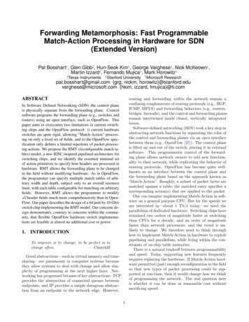
2 About Your Thermostat1723845123456786Day of Week.Displays the current day of weekProgram Event Indicator.Indicates the current program eventTime of Day.Displays the current time of daySystem Status Indicator.Flashes when heat or cool is runningLow Battery Indicator.Indicates when batteries need to be replacedHold Mode Indicator.Displays if in HOLD modeRoom Temperature*.Displays the current room temperatureSet Temperature*.Displays the current set point temperatureService Filter Indicator.Displays a filter service reminder*The room temperature is normally shown. To view the set temperature, brieflypress and release the button.7182910312345678910546Arrow Buttons.Used to increase or decrease settingsSystem Switch.Selects Heat, Cool or OffPROG Button.Selects programming modeHOLD Button.Enters/Exits the HOLD mode (program bypass)RETURN Button.Returns to normal from program or setting modesDAY/TIME Button.Used to set the time and day of weekReset Button.Resets thermostat clock and programBacklight Button.Illuminates the display backlightFan Switch.Selects the system fan modeBattery Compartment.Stores 2 “AA” Alkaline Batteries1
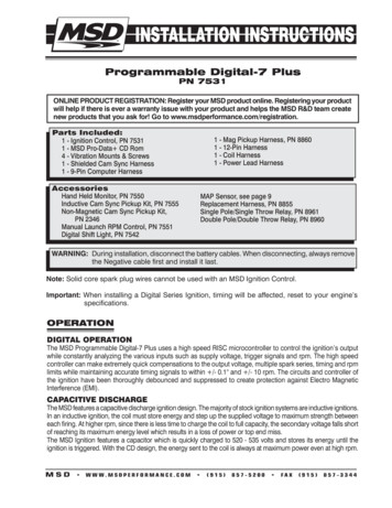
3 InstallationWarningDisconnect power before beginning installation.Thermostat LocationInstall the thermostat approximately 4-5 feet (1.2 - 1.5m) above the floorin an area that has a good amount of air circulation and maintains anaverage room temperature.Avoid installation in locations where the thermostat can be affected bydrafts, dead air spots, hot or cold air ducts, sunlight, appliances, concealedpipes, chimneys and outside walls.Install your new Braeburn thermostat in 5 basic steps:12345Install the Sub-BaseProvide PowerConnect Your WiresSet Installer SwitchesAttach Thermostat to Sub-Base1Install the Sub-Base: Remove the sub-base from the body of the thermostat. Mount the sub-base as shown below:Drill 3/16” pilot holes inyour desired location.Use supplied anchors fordrywall or plaster.2
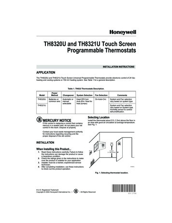
2Provide Power24VAC PowerTerminal (C)C For 24 Volt AC power, you must connect the common side of the transformer to the C terminal on the thermostat sub-base. For primary or back-up power, insert the 2 supplied “AA” type alkalinebatteries into the battery compartment located on the front of thethermostat, near the bottom. Make sure to position the Positive ( ) andNegative (-) sides of the batteries correctly with the /- symbols in thebattery compartment.3 Connect Your WiresWiring TerminationsTerminal FunctionDescriptionRc*Input24 Volt AC Cooling Transformer(Dual Transformer Systems Only)Rh*InputPower Connection (24 Volt AC HeatingTransformer or Millivolt Power Source)OOutputReversing Valve (Cool Active)BOutputReversing Valve (Heat Active)YOutputCompressor Relay (appears as Y1 on 2200NC)GOutputFan ControlWOutputConventional Heat RelayCInput24 Volt AC Transformer CommonAdditional Terminations (2200NC only)Terminal FunctionDescriptionW1/EOutput(W1) 1st Stage Conventional Heat(E) Emergency Heat RelayW2Output2nd Stage Heat / Auxiliary Heat* Appears as R on 2200NC (single transformer).3
Conventional SystemsTypical Wiring ConfigurationsNOTE: The “Installer Switch” option will be configured in the next step.Heat Only or MillivoltSet Installer Switch to NORMRh*WGCPower ConnectionHeat Relay (appears as W1/E on 2200NC)Fan Relay [note 4]24 Volt AC Transformer Common [note 1]1 HEAT / 1 COOL Single or Dual TransformerSet Installer Switch to NORMRh* 24 Volt AC Power (heating transformer) [note 2]Rc* 24 Volt AC Power (cooling transformer) [note 2]W Heat Relay (appears as W1/E on 2200NC)YGCCompressor Relay (appears as Y1 on 2200NC)Fan Relay24 Volt AC Transformer Common [note 1, 3]2 HEAT / 1 COOL Single Transformer (2200NC Only)Set System Type to NORMRW1W2Y1GC24 Volt AC PowerHeat Relay Stage 1Heat Relay Stage 2Compressor Relay Stage 1Fan Relay24 Volt AC Transformer Common [note 1]NOTES - Conventional Systems[1] If batteries are installed the 24 Volt AC common connection is optional.[2] Remove factory installed jumper for dual transformer systems.[3] In dual transformer systems, transformer common must come fromcooling transformer.[4] If needed for system.Provide disconnect and overload protection as required.* Appears as R on 2200NC (single transformer).4
Heat Pump SystemsTypical Wiring ConfigurationsNOTE: The “Installer Switch” option will be configured in the next step.1 HEAT / 1 COOL - No Auxiliary HeatSet Installer Switch to HPRh*24 Volt AC PowerRc*Connected to Rh with supplied Jumper WireO or B Changeover Valve [note 2]YGCCompressor Relay (appears as Y1 on 2200NC)Fan Relay24 Volt AC Transformer Common [note 1]* Appears as R on 2200NC (single transformer).2 HEAT / 1 COOL - Including Auxiliary Heat (2200NC only)Set Installer Switch to HPR24 Volt AC PowerO or B Changeover Valve [note 2]Y1Compressor Relay (1st stage heating/cooling)W2Auxiliary Heat Relay (2nd stage heating) [note 3]EEmergency Heat Relay [note 3]GFan RelayC24 Volt AC Transformer Common [note1]NOTES - Heat Pump Systems[1] If batteries are installed the 24 Volt AC common connection is optional.[2] Select O for cool active or B for heat active.[3] Install a field supplied jumper between the W2 and E terminals ifthere is no separate emergency heat relay installed.Provide disconnect and overload protection as required.4Set Installer SwitchesThe Installer switches are located on the back of the thermostat and mustbe properly configured for this thermostat to operate properly.SwitchFactory SettingDefault Options CommentsNORM / HP CONVNORMHPSelect for conventional systemsSelect for heat pump systemsF/CFFCSelect for fahrenheit temperature scaleSelect for celsius temperature scaleHE / HGHGHGHESelect for gas heatSelect for electric heatNOTE: The reset button must be pressed after making any changes tothese switches.5
5Attach Thermostat to Sub-Base1. Line up the thermostat body with the sub-base.2. Carefully push the thermostat body against the sub-base until it snapsinto place.NOTE: The thermostathinges from the topand latches atthe bottom.4 System TestingWarning Read Before Testing Do not short (or jumper) across terminals on the gas valve or at theheating or cooling system control board to test the thermostat installation. This could damage the thermostat and void the warranty. Do not select the COOL mode of operation if the outside temperatureis below 50º F (10º C). This could possibly damage the controlled cooling system and may cause personal injury. This thermostat includes an automatic compressor protection feature toavoid potential damage to the compressor from short cycling. Whentesting the system, make sure to take this delay into account.NOTE: The compressor delay can be bypassed by pressing the reset buttonon the front of the thermostat. All user settings will be returned to factorydefault.1 Move the SYSTEM switch to HEAT mode.2 Press to raise the set temperature a minimum of 3 degrees abovethe current room temperature. The system should start within a fewseconds. With a gas heating system, the fan may not start right away.3 Move the SYSTEM switch to the OFF mode. Allow the heating system tofully shut down.4 Move the SYSTEM switch to the COOL mode.5 Press to lower the set temperature a minimum of 3 degrees belowthe current room temperature. The system should start within a fewseconds (unless compressor short cycle protection is active – Seenote above).6 Move the SYSTEM switch to the OFF mode. Allow the cooling system tofully shut down.7 Move the FAN switch to the ON mode. The system fan should startwithin a few seconds.8 Move the FAN switch to the AUTO mode. Allow the system fan to turn off.6
5 Setting User OptionsAdvanced User OptionsUser options allow you to customize some of your thermostat’s features.Most users will not need to make any changes to the settings in this section.To access the User Options menu, hold down the RETURN button forapproximately 3 seconds until the screen changes and displays thefirst User Option.Press the or button to change the setting for the displayed User Option.After you have made your desired setting, press RETURN to advance to thenext User Option.The thermostat will return to normal mode after your last user option ismade or after no keys have been pressed for 5 seconds.Table of User omments11st stage0.5differential0.5, 1.0,2.0Select a 1st stage temperaturedifferential of 0.5 , 1.0 or 2.0 F(0.2 , 0.5 or 1.0 C)22nd stage2.0differential(2200NC Only)1.0, 2.0,3.0, 4.0,5.0, 6.0Select a 2nd temperaturedifferential of 1 , 2 , 3 , 4 , 5 or 6 F(0.5 , 1 , 1.5 , 2 , 2.5 or 3 C)3ExtendedLGHoldPeriodLGSelects long (permanent) hold mode5HSelects 24 hr. (temporary) hold ARMTM)REC OFO00Disables filter service monitor feature30, 60,90, 180Selects a number of days beforethe thermostat will flash a ServiceFilter reminder in the display.REC OFDisables adaptive (early)recovery modeREC ONEnables adaptive (early)recovery modeDetailed Explanation of User Options:Temperature Differential(User Option 1 and 2)The differential setting is the temperature control range that your thermostatwill provide. The smaller the setting, the tighter your range of temperaturecontrol and comfort will be. The 2nd stage differential is only for systemswith a second stage of heating (auxiliary heat).7
Extended Hold Period(User Option 3)The Extended Hold Period lets you select the period your thermostat willhold the temperature when the HOLD mode is activated (See “TemperatureAdjustment”). When LG is selected the thermostat will stay in hold modeuntil turned off. When SH is selected, the thermostat will hold yourtemperature for 24 hours and then return to the current program at that time.Service Filter Monitor(User Option 4)The Service Filter Monitor is a user selectableservice monitor that will display a reminder fora required air filter replacement by flashing theFILT segment in the display. When the time hasexpired, and required cleaning or replacementhas been performed, touch the RETURN buttonto reset the timer and reset the service monitor.Select 000 (off) or a set number of days before the reminder will appear.Adaptive Recovery Mode (early recovery)(User Option 5)During Adaptive Recovery Mode (ARM ), room temperature is recoveredgradually by turning on the heating or cooling before the end of the setback period. The set point temperature is changed to that of the upcomingprogram temperature.6 Setting Your Program ScheduleSetting the Time and Day1. In normal operating mode, press the DAY/TIMEbutton. The display will switch to the day/timesetting mode and the hour will be flashing.2. Press or to adjust the hour.Press DAY/TIME.3. Press or to adjust the minute. PressDAY/TIME.4. Press or to adjust the day of the week. Press RETURN to exit.Tips Before Setting Your Program Schedule Make sure your current time and day of the week are set correctly. When programming, make sure the AM and PM indicators are correct. Your NIGHT event cannot exceed 11:50 PM.This thermostat comes pre-programmed with a default energy savingprogram. The following table outlines the pre-programmed times andtemperatures for heating and cooling in each of your 4 daily weekday andweekend events. If you wish to use these settings then no further programming is necessary:8
5-2 Day Programming– Weekday/WeekendFactory Settings4 EventWeekdayWeekendMORNTime: 6:00 amHeat: 70 F (21 C)Cool: 78 F (26 C)Time: 6:00 amHeat: 70 F (21 C)Cool: 78 F (26 C)Time: 8:00 amHeat: 62 F (17 C)Cool: 85 F (29 C)Time: 6:00 pmHeat: 70 F (21 C)Cool: 78 F (26 C)Time: 10:00 pmHeat: 62 F (17 C)Cool: 82 F (28 C)Time: 8:00 amHeat: 62 F (17 C)Cool: 85 F (29 C)Time: 6:00 pmHeat: 70 F (21 C)Cool: 78 F (26 C)Time: 10:00 pmHeat: 62 F (17 C)Cool: 82 F (28 C)DAYEVENIGHTProgramming a 5-2 Day ScheduleThe 5-2 day programming mode allows you to program Monday - Fridaywith one 4 event schedule and then allows you to change Saturday andSunday with a different 4 event schedule.1. Press the PROG button. The display will switchto programming mode. The days M, TU,
NOTE: The compressor delay can be bypassed by pressing the reset button on the front of the thermostat. All user settings will be returned to factory default. 1 Move the SYSTEM switch to HEAT mode. 2 Press to raise the set temperature a minimum of 3 degrees above the current room temperature. The system should start within a few seconds. With a gas heating system, the fan may not start right .