Transcription
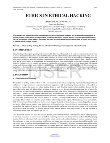
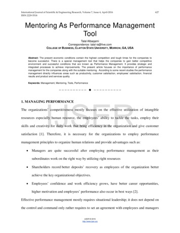
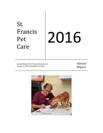
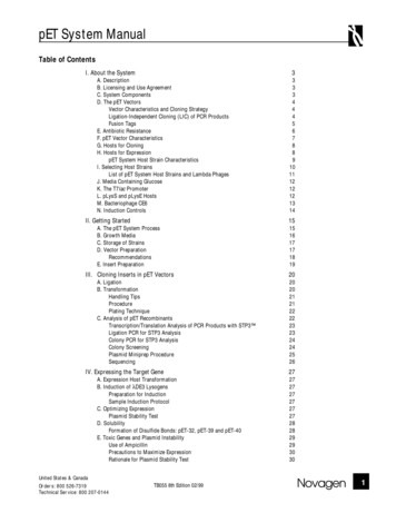
International Journal of Scientific Engineering and Research (IJSER)www.ijser.inISSN (Online): 2347-3878, Impact Factor (2014): 3.05Programmable Pet FeederTessema Gelila Berhan1, Worku Toyiba Ahemed2, Tessema Zelalem Birhan3Tianjin University of Technology and Education (TUTE), School of Electronics Engineering, Tianjin, 300222, P.R.CHINAAbstract: Over the years, more and more households are beginning to have pets. Pet feeders came into existence as more and more petowners found it difficult to cater time to feed their pets. Pet feeders are automated machines that dispense food at preset schedule. Theyare mainly timed based and dispense a certain amount of food at specific time of the day. The pet feeder is a programmable system whichis mainly controlled by a microcontroller. It consists of a LCD screen for input display, buzzer to alert pets for meals, stepper motor tocontrol the speed and a turn table which is divided into different sections for placement of different food. User will be able to select thefood to be dispensed out at their desired timing.Keywords: Turn-table, PIC18F4520 microcontroller, Buzzer Stepper Motor, DC motor1. Introduction1.1 BackgroundPet feeding can be difficult in this busy age but the perfectPet feeder delivers a worry free solution to modern, caringpet-parents while away. There are many various types ofautomated pet feeding devices in the market now.Generally most pet feeders are commonly for cats anddogs but for a few special cases, some pet feeders forinstances, like the fish pet-feeder or the hamster pet feederare specifically designed to suit only for that particulartype of pet due to their size and environmental livingconditions.1.2 OverviewThe design of the programmable pet feeder can be brokendown into 2 stages. The first stage is the construction ofindividual components and the second stage involvesinterfacing the components with the goal of operating asone unit. During the construction stage, the componentscan be categorized as either hardware or ontroller, LCD, buzzer and motors. The basicsoftware component consists of a motor control algorithmand a delay timer algorithm. User will input data on theLCD and the 40 pin microcontroller which is the brain ofthe pet feeder will perform motor control and delayalgorithms.2. ObjectiveThere are some objective needs to be archived in order toaccomplish this project. But the main objective of theproject is to design a programmable system which is ableto(I) Serve food for pets at programmable times(ii) Enhance the performance and stability of the system.(iii) Develop the system that works automatically.The project shall adopt the Structured System Analysisand Design methodology approach to achieve the projectobjective.Paper ID: IJSER15587Figure 1: Block diagram of pet feeder systemThe system will consist of the following modules:1. Power supply to supply voltages to each modules2. Microcontroller for programming and controlling3. Buzzer for alerting pets4. Stepper Motors to control the speed and positioning5. Turn table to rotate at programmable time6. LCD (Liquid Crystal Display)3. Hardware SystemHardware Implementation1. Micro-controller- programming and controlling2. Power Supply- supply voltages3. Stepper motor- to control the speed and positioning4. Turn-Table- to rotate at programmable time5. DC motor-to dispense food Buzzer-sound for alerting3.1 Microchip Microcontroller (18F Series)ThisfamilyoffersthePIC18microcontrollers mainly:advantagesofallHigh computational performance at an economical pricewith addition of high endurance Enhanced Flash programmemory Design enhancements for many highperformances, power sensitive applications.3.1.1 PIC18F4520The microchip PIC18F4520 microcontroller is a 40 pin 8bit processor with five ports available to be useddepending on the device selected and features enabled.Some pins of the I/O ports are multiplexed with analternate function from the peripheral features on theVolume 3 Issue 11, November 2015Licensed Under Creative Commons Attribution CC BY99 of 104
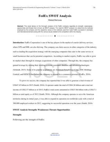
International Journal of Scientific Engineering and Research (IJSER)www.ijser.inISSN (Online): 2347-3878, Impact Factor (2014): 3.05device. In general, when a peripheral is enabled, that pinmay not be used as a general purpose I/O pin. It cancommunicate with the workstation through a UniversalSerial Bus (USB) to download or upload dataFigure 3: PICDEM 2 Plus boardFigure 2: PIC18F4520 microcontrollerFigure 4: In-circuit debugger (MPLAB ICD 2)3.2 Microchip Development KitThe PICDEM 2 Plus is a simple board that comes togetherwith the microcontroller preinstalled. It demonstrates thecapabilities of many of the 18-, 28- and 40-pinPIC16XXXX and PIC18XXXX devices. It can be usedstand-alone with a programmed part, with an in circuitemulator (e.g., MPLAB ICE or MPLAB REAL ICE )or with an in-circuit debugger, MPLAB ICD 2. ThePICDEM PLUS Board has the following hardwarefeatures:1.2.3.4.5.6.7.8.9.10.11.12.13.1. 18, 28 and 40-pin DIP sockets. (Although threesockets are provided, only one device may be used ata time.)On-board 5V regulator for direct input from 9V, 100mA AC/DC wall adapter or 9V battery, or hooks for a 5V, 100 mA regulated DC supply.RS-232 socket and associated hardware for directconnection to an RS-232 interface.In-Circuit Debugger (ICD) connector.5 K potentiometer for de vices with analog inputs.Three push button switches for external stimulus andReset.Power-on indicator LED.Four LEDs connected to PORTBJumper J6 to disconnect LEDs from PORTB4 MHz canned crystal oscillatorUnpopulated holes provided for crystal connectionJumper J7 to disconnect on-board RC oscillator(approximately 2 MHz)15. LCD display and 16. Piezo buzzerPaper ID: IJSER15587Figure 5: MPLAB ICD 2 RJ-11 Pin out (The MPLABICD 2 is connected to the PICDEM 2 Plus board using RJ11)3.3 Stepper MotorA stepper motor, as its name suggests, moves one step at atime, unlike those conventional motors, which spincontinuously. If we command a stepper motor to movesome specific number of steps, it rotates incrementally thatmany number of steps and stops. Because of this basicnature of a stepper motor, it is widely used in low cost,open loop position control systems. Open loop controlmeans no feedback information about the position isneeded. This eliminates the need for expensive sensing andfeedback devices, such as optical encoders. Motor positionis known simply by keeping track of the number of inputstep pulses.These motors feature enhanced mini-angle stepping withgood speed/ torque characteristics over a wide size range.The Hybrid Stepper ranges comprise six main types orframe sizes each offered in one or more basic step angles.Parameters such as the supply voltage, drive electronicsand size constraints determine the type of stepper that canbe employed.Volume 3 Issue 11, November 2015Licensed Under Creative Commons Attribution CC BY100 of 104
International Journal of Scientific Engineering and Research (IJSER)www.ijser.inISSN (Online): 2347-3878, Impact Factor (2014): 3.05Figure 9: DC motorFigure 6: Unipolar Stepper Motors3.6 Power SupplyThe PICDEM 2 plus Board can be powered using a 100240V, 100mA AC/DC wall adapter. The adaptor will stepthe voltage down to 9V and to be plugged into J2 of theboard. The 9V will then be regulated to 5V using a voltageregulator atFigure 7: Astrosyn stepper motor3.4 BuzzerA buzzer or beeper is an electric signaling device thatmakes a buzzing sound. It commonly consists of a numberof switches or sensors connected to a control unit thatdetermines if and which button was pushed or a presettime has lapsed, and usually illuminates a light on theappropriate button or control panel, and sounds a warningin the form of a continuous or intermittent buzzing orbeeping sound.Figure 10: Connection of adaptor to J2 of board3.7 Turn-TableThe turn-table is some sort of a container which is dividedinto 4 sections. The motor will be placed at the bottom tohold and control the positioning.Uses of buzzer: Alert pets it is time for meals Alert pets that food is dispensingFigure 11: Turn-table4. Software DevelopmentFigure 8: Buzzer3.5 DC MotorA DC (direct-current) motor works by converting electricpower into mechanical. This is accomplished by forcingcurrent through a coil and producing a magnetic field thatspins the motor. In this project the DC-motor will be usedto dispense the food.Paper ID: IJSER15587The software programming for the STC89C52RCMicrocontroller is C-program and will be compiled usingC18 compiler of the MPLAB Integrated DevelopmentEnvironment. This software provides a single integratedenvironment to develop codes for embeddedmicrocontrollers.Volume 3 Issue 11, November 2015Licensed Under Creative Commons Attribution CC BY101 of 104
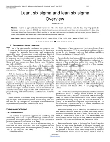
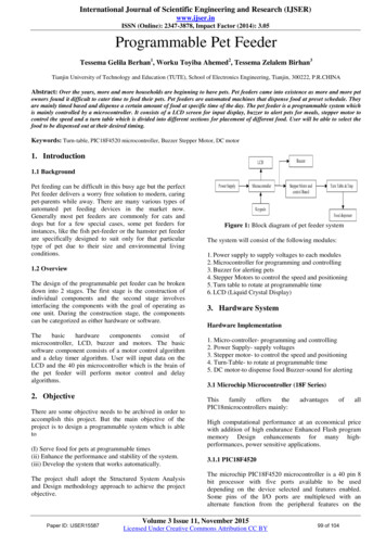
International Journal of Scientific Engineering and Research (IJSER)www.ijser.inISSN (Online): 2347-3878, Impact Factor (2014): 3.054.1 MPLAB Integrated Development Environment(IDE)MPLAB Integrated Development Environment (IDE) is afree, integrated toolset for the development of embeddedapplications employing Microchip's PIC microcontrollers.It is easy to use and includes a host of free softwarecomponents for fast application development and supercharged debugging. MPLAB support both AssemblyLanguage and C programming languages, others languagemay be supported through the use of third party programs.4.2 Process Flow Chart4.2.1 MPLAB IDEThe MPLAB IDE is a windows operating system (OS)software program that runs on a PC to developapplications for Microchip microcontrollers and digitalsignal controllers. It is called an IDE (IntegratedDevelopment Environment) because it provides a singleintegrated “environment” to develop code for embeddedmicrocontrollers.Figure 13: Flowchart of the Pet feeder4.4 Software Programming4.4.1 Motor4.2.2 MPLAB ConfigurationBefore starting development, you need to select the deviceand decide which development tools to use. There are anumber of processors available supported. In this project,the PIC18F4520 is used.Figure 14: Flowchart of Motor4.4.2 TimerFigure 12: Selecting the deviceThe other important program in this project is the timerprogram. It is used to set the time before the motor beginsto rotate. In this program, I have only used the 3 delayoptions mainly 5s, 10s and 15s to act as the timer for thisproject.4.3 Overview of the ProgramThe flowchart below illustrates the whole process of theprogram.Paper ID: IJSER15587Volume 3 Issue 11, November 2015Licensed Under Creative Commons Attribution CC BY102 of 104
International Journal of Scientific Engineering and Research (IJSER)www.ijser.inISSN (Online): 2347-3878, Impact Factor (2014): 3.05Figure 15: Flowchart of timer4.4.3 Buzzer and DC MotorThe aim of the dc motor is to dispense food from the turntable and the buzzer is to act as an alarm to notify pets thatit is time for their meals. The program written for these 2modules are explained together as they are similar. Boththe buzzer and dc motor will always be in the waitingmode. They will only be activated once the turn-table is inposition. Both the buzzer and the dc motor will then be onfor 5 seconds before it turns off and back to the waitingmode./* configure LCD pin */TRISDbits.TRISD7 0; // VEE // PICDEM2 PLUSGREEN BOARDTRISDbits.TRISD6 0; // ENTRISDbits.TRISD5 0; // RWTRISDbits.TRISD4 0; // RSTRISDbits.TRISD0 0; // DB4TRISDbits.TRISD1 0; // DB5TRISDbits.TRISD2 0; // DB6TRISDbits.TRISD3 0; // DB7TRISA 0xf0;TRISB 0x01; //Portpins RB1-RB3 as outputs TRISC 0x00;Lcd VEE 1;Delay10KTCYx(15);Write Lcd (0x20,0);Write Lcd (0x28,0);Write Lcd (0x0c,0);Write Lcd (0x01,0);5. ConclusionThis project has been a very rewarding experience for me.As I am not working in the semi-con industry, this projecthas given me a chance to get more exposure in the field ofelectronics. As this project consists of both hardware andsoftware, I was given the opportunity to get some handson and design experience on the hardware part. Inaddition, the development of software algorithm alsoallows me to incorporate the reasoning and logical skills.Throughout the development phase of this project, manyaspects of the electronic, mechanical and programminghave been touched on and it has been an interesting. Mostof the time is spent on the software portion. The mostchallenging issues that I faced are writing and debuggingof software algorithm codes. Many areas need to bestudied and considered thoroughly as I am not familiarwith microcontroller and the programming language.Figure 16: Flowchart of buzzer and dc motor4.5 Source Code/********************************/#include p18f4520.h #include delays.h /* macro for LCD */#define Lcd VEE LATDbits.LATD7 // VEE - lcdcontrast#define Lcd EN LATDbits.LATD6 // Enable signal#define Lcd RW LATDbits.LATD5 // read write signal#define Lcd RS LATDbits.LATD4 // register selectsignal/* function declaration */ void Lcd Title (void);Voidmotor (void);Void Write Lcd (unsigned char, unsignedchar); voidDelayFor18TCY (void); /* global variables */ unsignedchar count; int Tray; int Delay;Voidmain (void){/* configure port */ADCON1 0x0F; // default all pins to digitalPaper ID: IJSER15587Overall, I have gained a lot of knowledge and experiencein this project due to its broad engineering nature in areasof hardware and software design. I have learned to sourcefor solutions when problems are encountered. This projecthas greatly improved my project management skills.Finally I believed what I have learned throughout thecourse especially in this module will greatly help me in myfuture career.ReferencesInternet:1. http //www.perfectpetfeeder.com Accessed on 20 Feb20092. tml3. http://en.wikipedia.org/wiki/Microcontrollers4. ppid 1Volume 3 Issue 11, November 2015Licensed Under Creative Commons Attribution CC BY103 of 104
International Journal o
The PICDEM 2 plus Board can be powered using a 100-240V, 100mA AC/DC wall adapter. The adaptor will step the voltage down to 9V and to be plugged into J2 of the board. The 9V will then be regulated to 5V using a voltage regulator at . Figure 10: Connection of adaptor to J2 board . 3.7 Turn-Table . The turn-table is some sort a container which divided be placed at the bottom to hold and control .