Transcription
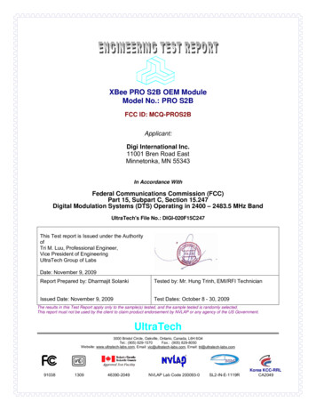
XBee PRO S2B OEM ModuleModel No.: PRO S2BFCC ID: MCQ-PROS2BApplicant:Digi International Inc.11001 Bren Road EastMinnetonka, MN 55343In Accordance WithFederal Communications Commission (FCC)Part 15, Subpart C, Section 15.247Digital Modulation Systems (DTS) Operating in 2400 – 2483.5 MHz BandUltraTech's File No.: DIGI-020F15C247This Test report is Issued under the AuthorityofTri M. Luu, Professional Engineer,Vice President of EngineeringUltraTech Group of LabsDate: November 9, 2009Report Prepared by: Dharmajit SolankiTested by: Mr. Hung Trinh, EMI/RFI TechnicianIssued Date: November 9, 2009Test Dates: October 8 - 30, 2009The results in this Test Report apply only to the sample(s) tested, and the sample tested is randomly selected.This report must not be used by the client to claim product endorsement by NVLAP or any agency of the US Government.UltraTech3000 Bristol Circle, Oakville, Ontario, Canada, L6H 6G4Tel.: (905) 829-1570Fax.: (905) 829-8050Website: www.ultratech-labs.com, Email: vic@ultratech-labs.com, Email: tri@ultratech-labs.com91038130946390-2049NVLAP Lab Code 200093-0SL2-IN-E-1119RKorea KCC-RRLCA2049
FCC Part 15, Subpart C, Section 15.247 – DTSContents iXBee PRO S2B OEM Module, Model PRO S2BFCC ID: MCQ-PROS2BTABLE OF CONTENTSEXHIBIT 1.SUBMITTAL CHECK LIST. 1EXHIBIT 2.INTRODUCTION . 22.1.2.2.2.3.SCOPE. 2RELATED SUBMITTAL(S)/GRANT(S) . 2NORMATIVE REFERENCES . 2EXHIBIT 3.3.1.3.2.3.3.3.4.3.5.3.6.CLIENT INFORMATION. 3EQUIPMENT UNDER TEST (EUT) INFORMATION . 3EUT’S TECHNICAL SPECIFICATIONS . 4ASSOCIATED ANTENNA DESCRIPTION . 4LIST OF EUT’S PORTS. 4ANCILLARY EQUIPMENT . 5EXHIBIT 4.4.1.4.2.EUT OPERATING CONDITIONS AND CONFIGURATIONS DURING TESTS . 6CLIMATE TEST CONDITIONS . 6OPERATIONAL TEST CONDITIONS & ARRANGEMENT FOR TESTS . 6EXHIBIT 5.5.1.5.2.5.3.PERFORMANCE ASSESSMENT . 3SUMMARY OF TEST RESULTS . 7LOCATION OF TESTS. 7APPLICABILITY & SUMMARY OF EMC EMISSION TEST RESULTS . 7MODIFICATIONS INCORPORATED IN THE EUT FOR COMPLIANCE PURPOSES. 7EXHIBIT 6.MEASUREMENTS, EXAMINATIONS & TEST DATA FOR EMC EMISSIONS. 86.1. TEST PROCEDURES. 86.2. MEASUREMENT UNCERTAINTIES . 86.3. MEASUREMENT EQUIPMENT USED . 86.4. ESSENTIAL/PRIMARY FUNCTIONS AS DECLARED BY THE MANUACTURER. 86.5. AC POWER LINE CONDUCTED EMISSIONS [§15.207(A)]. 96.6. OCCUPIED BANDWIDTH [§ 15.247(A)(2)]. 126.7. PEAK CONDUCTED OUTPUT POWER - DTS [§ 15.247(B)(3)]. 23ANTENNA 1: TYPE- DIPOLE, GAIN- 2.1 DBI, OPERATES ON CHANNELS # 11 TO 26 . 24ANTENNA 2: TYPE- ASTRON OMNI DIRECTIONAL, GAIN- 8 DBI, OPERATES ON CHANNELS # 11 TO 25 . 24ANTENNA 3: TYPE- D-LINK OMNI DIRECTIONAL, GAIN- 15 DBI, OPERATES ON CHANNELS # 11 TO 24 . 25ANTENNA 4: TYPE- MAXRAD YAGI, GAIN- 15 DBI, OPERATES ON CHANNELS # 11 TO 24 . 25ANTENNA 5: TYPE- ARC PANEL, GAIN- 19 DBI, OPERATES ON CHANNELS # 11 TO 24. 256.8. TRANSMITTER BAND-EDGE & SPURIOUS CONDUCTED EMISSIONS [§ 15.247(D)]. 266.9. TRANSMITTER SPURIOUS RADIATED EMISSIONS AT 3 METERS [§§ 15.247(D), 15.209 & 15.205] . 516.10.POWER SPECTRAL DENSITY [§ 15.247(E)] . 886.11.RF EXPOSURE REQUIRMENTS [§§ 15.247(E)(I), 1.1310 & 2.1091] . 94EXHIBIT 7.7.1.7.2.MEASUREMENT UNCERTAINTY. 96LINE CONDUCTED EMISSION MEASUREMENT UNCERTAINTY . 96RADIATED EMISSION MEASUREMENT UNCERTAINTY . 97ULTRATECH GROUP OF LABS3000 Bristol Circle, Oakville, Ontario, Canada L6H 6G4Tel. #: 905-829-1570, Fax. #: 905-829-8050, Email: vic@ultratech-labs.com, Website: http://www.ultratech-labs.comFile #: DIGI-020F15C247November 9, 2009All test results contained in this engineering test report are traceable to National Institute of Standards and Technology (NIST)
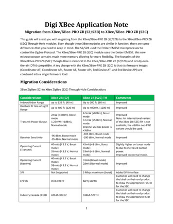
FCC Part 15, Subpart C, Section 15.247 – DTSPage 1XBee PRO S2B OEM Module, Model PRO S2BFCC ID: MCQ-PROS2BEXHIBIT 1.SUBMITTAL CHECK LISTAnnex No.Exhibit Type--Test ReportQualityCheck (OK)OKDescription of Contents Exhibit 1: Submittal check listsExhibit 2: IntroductionExhibit 3: Performance AssessmentExhibit 4: EUT Operation and Configurationduring TestsExhibit 5: Summary of test ResultsExhibit 6: Measurement DataExhibit 7: Measurement UncertaintyPower Line Conducted Emissions Setup PhotosRadiated Emissions Setup Photos 1Test Setup Photos 2External EUT PhotosExternal EUT PhotosOK3Internal EUT PhotosInternal EUT PhotosOK4Cover Letters Letter from Ultratech for Certification RequestLetter from the Applicant to appoint Ultratech toact as an agentLetter from the Applicant to request forConfidentiality FilingLetter from the Applicant to request for ModularApprovalOKOK5Attestation Statements----6ID Label/Location InfoID Label and Location of LabelOK7Block DiagramsBlock DiagramOK8Schematic DiagramsSchematicsOK9Parts List/Tune Up InfoParts ListOK10Operational DescriptionOperation DescriptionOK11RF Exposure InfoMPE Evaluation, see section 6.11 in this Test Reportfor details.OK12Users ManualXBee / XBee-PRO ZB RF ModulesOKULTRATECH GROUP OF LABS3000 Bristol Circle, Oakville, Ontario, Canada L6H 6G4Tel. #: 905-829-1570, Fax. #: 905-829-8050, Email: vic@ultratech-labs.com, Website: http://www.ultratech-labs.comFile #: DIGI-020F15C247November 9, 2009All test results contained in this engineering test report are traceable to National Institute of Standards and Technology (NIST)
FCC Part 15, Subpart C, Section 15.247 – DTSPage 2XBee PRO S2B OEM Module, Model PRO S2BFCC ID: MCQ-PROS2BEXHIBIT 2.2.1.INTRODUCTIONSCOPEReference:FCC Part 15, Subpart C, Section 15.247Title:Code of Federal Regulations (CFR), Title 47 – Telecommunication, Part 15Purpose of Test:Equipment Certification for Digital Modulation Systems (DTS) TransmitterOperating in the Frequency Band 2400-2483.5 MHz.Test Procedures:Both conducted and radiated emissions measurements were conducted inaccordance with American National Standards Institute ANSI C63.4 - AmericanNational Standard for Methods of Measurement of Radio-Noise Emissions fromLow-Voltage Electrical and Electronic Equipment in the Range of 9 kHz to 40 GHz.[x] Commercial, industrial or business environment[x] Residential environmentEnvironmentalClassification:2.2.RELATED SUBMITTAL(S)/GRANT(S)None.2.3.NORMATIVE REFERENCESPublicationYearTitle47 CFR Parts 0-192008Code of Federal Regulations – TelecommunicationANSI C63.42003CISPR 22 &EN 55022CISPR 16-1-1200620062003CISPR 16-2-12003KDB PublicationNo. 558074FCC Public NoticeDA 00-14072005American National Standard for Methods of Measurement of RadioNoise Emissions from Low-Voltage Electrical and Electronic Equipmentin the Range of 9 kHz to 40 GHzInformation Technology Equipment - Radio Disturbance Characteristics– Limits and Methods of MeasurementSpecification for radio disturbance and immunity measuring apparatusand methods. Part 1-1: Measuring ApparatusSpecification for radio disturbance and immunity measuring apparatusand methods. Part 2-1: Conducted disturbance measurementGuidance on Measurements for Digital Transmission Systems (47 CFR15.247)Part 15 Unlicensed Modular Transmitter Approval2000ULTRATECH GROUP OF LABS3000 Bristol Circle, Oakville, Ontario, Canada L6H 6G4Tel. #: 905-829-1570, Fax. #: 905-829-8050, Email: vic@ultratech-labs.com, Website: http://www.ultratech-labs.comFile #: DIGI-020F15C247November 9, 2009All test results contained in this engineering test report are traceable to National Institute of Standards and Technology (NIST)
FCC Part 15, Subpart C, Section 15.247 – DTSPage 3XBee PRO S2B OEM Module, Model PRO S2BFCC ID: MCQ-PROS2BEXHIBIT 3.3.1.PERFORMANCE ASSESSMENTCLIENT INFORMATIONAPPLICANTName:Digi International Inc.Address:11001 Bren Road EastMinnetonka, MN 55343USAContact Person:Mr. Paul DahlPhone #: 801-765-9885Fax #: 801-765-9895Email Address: Paul.dahl@digi.comMANUFACTURERName:Digi International Inc.Address:11001 Bren Road EastMinnetonka, MN 55343USAContact Person:Mr. Paul DahlPhone #: 801-765-9885Fax #: 801-765-9895Email Address: Paul.dahl@digi.com3.2.EQUIPMENT UNDER TEST (EUT) INFORMATIONThe following information (with the exception of the Date of Receipt) has been supplied by the applicant.Brand Name:Digi International Inc.Product Name:XBee PRO S2B OEM ModuleModel Name or Number:PRO S2BSerial Number:Test SampleType of Equipment:Digital Modulation TransmitterInput Power Supply Type:3.3 Vdc using TENMA DC Regulated Power SupplyModel: 72-7295Wireless modemPrimary User Functions of EUT:ULTRATECH GROUP OF LABS3000 Bristol Circle, Oakville, Ontario, Canada L6H 6G4Tel. #: 905-829-1570, Fax. #: 905-829-8050, Email: vic@ultratech-labs.com, Website: http://www.ultratech-labs.comFile #: DIGI-020F15C247November 9, 2009All test results contained in this engineering test report are traceable to National Institute of Standards and Technology (NIST)
FCC Part 15, Subpart C, Section 15.247 – DTSPage 4XBee PRO S2B OEM Module, Model PRO S2BFCC ID: MCQ-PROS2B3.3.EUT’S TECHNICAL SPECIFICATIONSTRANSMITTEREquipment Type: Intended Operating Environment:Commercial, industrial or businessPower Supply Requirement:2.7VDC to 3.6VDC from -40 to 85CRF Output Power Rating:83.56 mW ( 19.22 dBm) – High Power Setting0.75 mW (-1.27 dBm) – Low Power SettingOperating Frequency Range:2405 – 2480 MHzRF Output Impedance:50 OhmsChannel Spacing:5 MHzDuty Cycle:27%6 dB bandwidth:1.75 MHzModulation Type:QPSKOscillator Frequencies:4.8 GHzAntenna Connector/Types: 3.4.MobileBase Station (fixed use)IntegralUnique connector (RPSMA/U.FL)ASSOCIATED ANTENNA DESCRIPTIONThe highest gain antenna from each type of antenna was selected for testing to represent the worst case. Thefollowing antennas were selected for testing in this filing:1.2.3.4.5.3.5.Dipole Antenna (P/N: A24-HABSM; Max. Antenna Gain: 2.1 dBi)Astron Omni-directional Antenna (P/N: A24-F8NF; Max. Antenna Gain: 8 dBi)D-Link Omni-directional Antenna (P/N: A24-F15NF; Max. Antenna Gain: 15 dBi)Maxrad Yagi Antenna (P/N: A24-Y18NF; Max. Antenna Gain: 15 dBi)ARC Panel Antenna (P/N: A24-P19NF; Max. Antenna Gain: 19 dBi)LIST OF EUT’S PORTSPortNumberEUT’s Port DescriptionNumber ofIdentical PortsConnector TypeCable Type(Shielded/Non-shielded)1RF Port1RPSMA/U.FLShielded2DC Supply & I/O Port1Pin HeaderNo cable, direct connectionULTRATECH GROUP OF LABS3000 Bristol Circle, Oakville, Ontario, Canada L6H 6G4Tel. #: 905-829-1570, Fax. #: 905-829-8050, Email: vic@ultratech-labs.com, Website: http://www.ultratech-labs.comFile #: DIGI-020F15C247November 9, 2009All test results contained in this engineering test report are traceable to National Institute of Standards and Technology (NIST)
FCC Part 15, Subpart C, Section 15.247 – DTSPage 5XBee PRO S2B OEM Module, Model PRO S2BFCC ID: MCQ-PROS2B3.6.ANCILLARY EQUIPMENTThe EUT was tested while connected to the following representative configuration of ancillary equipmentnecessary to exercise the ports during tests:Ancillary Equipment # 1Des
XBee PRO S2B OEM Module Model No.: PRO S2B FCC ID: MCQ-PROS2B Applicant: Digi International Inc. 11001 Bren Road East Minnetonka, MN 55343 In Accordance With Federal Communications Commission (FCC) Part 15, Subpart C, Section 15.247 Digital Modulation Systems (DTS) Operating in 2400 – 2483.5 MHz Band UltraTech's File No.: DIGI-020F15C247 This Test report
