Transcription
INSTALLATION ANDOPERATION MANUALHeat PumpPool & SpaHeaterModel Series2450, 3450, 4450,5450, 6450,6450PD, 6450HC,8450 & 8450HCFOR YOUR SAFETY: Do not store or use gasoline or other flammable vapors andliquids or other combustible materials in the vicinity of this or any other appliance.To do so may result in an explosion or fire.NOTE: The instructions in this manual are for the use of qualified individuals specially trained and experiencedin the installation and maintenance of this type of equipment and related system components. Installation andservice personnel are required by some states to be licensed. Persons not qualified shall not attempt to install,service, or maintain this equipment.This manual should be maintained in legible condition and kept adjacent to the heat pump pool heater or in asafe place for future use.Catalog No. 6000.56CEffective: 01-12-18Replaces: 11-20-1792-105917-01-04
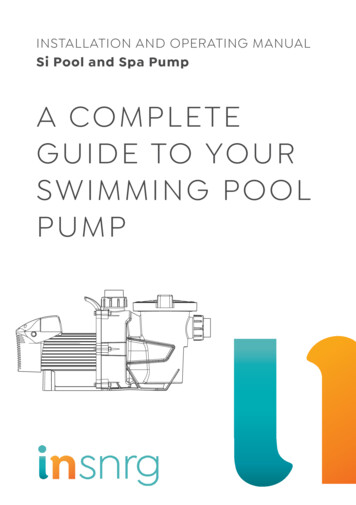
ATTENTION: Please Take This Opportunity to Quickly Register Your Unit!!While your unit is being installed by your professional and licensed installer of choice, Please Take ThisOpportunity to Quickly Register Your Unit!! With the necessary information in hand, Registering your new HeatPump Pool Heater only takes a few moments and is the only way to assure any verifiable warranty proceduresduring the span of your unit’s period of protection.Using the diagram at the bottom of the page (Fig. i) please locate and record your model and serial number.Once you have done this, please make sure you also have the following information on hand: Name, phone number, and email address of homeowner physical address of where the unit is installed; please include any ‘subdivision’ or similar information any service challenges present at the house/neighborhood: gated community, locked access at house,guard dog, etc. date of installation of the new unit name and phone number of the professional and licensed entity that performed the installation for youWith all of the above information in hand, pleasecontact us and ask to register your brand new heatpump or Online:http://warranty.raypak.comYou will be given a Warranty Registration Confirmationnumber which you should notate and keep in onelocation along with your Installation & Owner’s Manual,a copy of your warranty (provided with your manual)and the above information.This unit is equipped with a QR Code on the ratingplate, as shown in Fig. i, which will take you to thewww.raypak.com website where the IO manual andother documents can be easily accessed.NAMEPLATEThis would also be a good time to review both themanual and the warranty so that you are aware of howto correctly operate your new equipment as well ashow to keep from voiding any aspects of your warranty.During the life of your unit, please feel free to use theabove phone number, or the one conveniently locatedright on the unit, to contact us with any questions youmay have about operation, warranty, and/or service.QR CODEThank You Very Much Choosing us to Satisfy YourPool Heating needs!!Fig. i: Model and Serial Number LocationRev. 4 reflects the following:Additions: 2450-4450 Model Information.Warranty Registration Confirmation #:2
Water Chemistry(Corrosive water voids all warranties)For your health and the protection of your pool equipment, it is essential that your water be chemicallybalanced. The following levels must be used as a guide for balanced water.Recommended Level(s)Fiberglass PoolsFiberglass SpasOther Pool & Spa Types68 F to 88 F(20 C to 31 C)89 F to 104 F(32 C to 40 C)68 F to 104 F(20 C to 40 C)pH7.3 to 7.47.3 to 7.47.6 to 7.8Total Alkalinity (PPM)120 to 150120 to 15080 to 120Calcium Hardness (PPM)200 to 300150 to 200200 to 4004500 MAXIMUM4500 MAXIMUM4500 MAXIMUM2 to 32 to 32 to 33000 MAXIMUM**3000 MAXIMUM**3000 MAXIMUM**Water Temp. ( F / C)Salt (PPM)Free Chlorine (PPM)*Total Dissolved Solids (PPM)*Free Chlorine MUST NOT EXCEED 5 PPM!** In salt water chlorinated pools, the total TDS can be as high as 6000ppm. Occasional chemical shock dosing of the pool or spa water should not damage the heater providingthe water is balanced. However, it is highly recommended that the heat pump pool heater is isolatedvia shut off valves before any aggressive chemical treatment. Automatic chemical dosing devices and salt chlorinators are usually more efficient in heated water.Unless controlled, they can lead to excessive chlorine level which can damage your heater. Further advice should be obtained from your pool or spa builder, accredited pool shop, or chemicalsupplier for the correct levels for your water.3
ContentsWater Chemistry3Warnings5Pay Attention to These Terms5Introduction6Installation Considerations6Electrical Connections11Water Connections11Pressure Drop12HPPH Control Display12User Modes13HPPH Control Menus14USER MENU — Heat ONLY, PowerDefrost and Heat/Cool Models15INSTALLER/SERVICE MENU —HEAT ONLY Configuration17INSTALLER/SERVICE MENU —POWER DEFROST Configuration 21INSTALLER/SERVICE MENU —HEAT/COOL Configuration25Control Settings29Set Current Time29C/F Display 29Spa Max Temp29Pool Max Temp29Pump Periods29Temperature Control29Additional Features29Pump Control29Low Ambient (Outside) Lockout29Control Lock Box Mode29AUX Mode 30Remote Pool Operation31Pool Heat Mode31Pool Cool Mode (HEAT/COOL modelsONLY) 31Pool Auto Mode (HEAT/COOL modelsONLY) 31TIMED SPA Mode 31Fault History 31Run Hours/Cycles31Compressor Start Delay32Minimum Run Time32Defrost Operation323-Way Valve ControlBattery Back-upHigh Water Temperature LimitHigh Pressure Switch LockoutLow Pressure Switch LockoutWater Pressure SwitchSequence of OperationDigital Controls OperatingInstructionsTo Increase or Decrease the DesiredWater Temperature (Pool or Spa Mode)Select Temperature in C or FHeat/Cool OperationSystem Start-UpSeasonal Start-Up orAnnual CheckSummer ShutdownFreeze ProtectionSystem Drain-DownContinuous Pump OperationMaintenanceAir Coil CleaningCabinet Care (optional)Unplug Condensation Drain HolesTroubleshootingOperational Status MessagesError MessagesService Call VerificationPower SupplyWater FlowTime Clock AdjustmentSet Factory DefaultsService Access to HeatersPlumbing DiagramsWiring Diagram — 208V/230VSingle-Phase — Digital ModelsInstalling a Remote ControlDeviceHeater 2-Wire Controllers (Heat Only)3-Wire Controllers2-Wire Controllers For “Chill” Mode Heat/Cool Models OnlyResistance Sensor 6383940404040404042464747474748
Warnings—Pay Attention to These TermsDANGER:Indicates the presence of immediate hazards which will cause severe personal injury, deathor substantial property damage if ignored.WARNING:Indicates the presence of hazards or unsafe practices which could cause severe personalinjury, death or substantial property damage if ignored.CAUTION:Indicates the presence of hazards or unsafe practices which could cause minor personalinjury or product or property damage if ignored.NOTE:Indicates special instructions on installation, operation, or maintenance which are importantbut not related to personal injury hazards.This manual, as well as the pool/spa heat pump pool heater itself, contains ANSI-approved product safety signsand labels. Please read these signs and labels, as they convey important safety information about hazards thatmay be potentially present in and around the heat pump pool heater.CAUTION: Elevated water temperature can behazardous. The U.S. Consumer Product SafetyCommission has these guidelines:CAUTION: Improper chemical content in aswimming pool or spa can damage the heat pumppool heater. DO NOT add pool/spa chemicals to thepool/spa via the skimmer or any other apparatus(feeder, chlorinator, etc.) that is on the influentside (i.e. before) of the heater. This will damagethe heat pump pool heater and could void the heatpump pool heater warranty. ALWAYS follow theproduct manufacturer’s directions when adding anychemicals to your pool.1. Spa water temperatures should never exceed104 F (40 C). A temperature of 100 F (38 C)is considered safe for a healthy adult. Specialcaution is suggested for young children.2. Drinking of alcoholic beverages before or duringspa or hot tub use can cause drowsiness whichcould lead to unconsciousness and subsequentlyresult in drowning.WARNING: These heat pump pool heaters arecharged with R-410A refrigerant. Ensure that allservice work is done with gauges and equipmentsuitable for R-410A.3. Pregnant Women Beware! Soaking in water over102 F (39 C) can cause fetal damage duringthe first three months of pregnancy resulting inthe birth of a brain-damaged or deformed child.Pregnant women should stick to the 100 F (38 C)maximum rule.EFFICIENCY TESTING NOTICE: For purposesof verifying or testing efficiency ratings, the testprocedure in Title 10 APPENDIX P to Subpart Bof Part 430 (Uniform Test Method for Measuringthe Energy Consumption of Pool Heaters) andthe clarifying provisions provided in the AHRIOperations Manual 1160 that were applicable atthe date of manufacture should be used for test setup and performance. Charging Chart are availableat harging-charts. These should only be usedby certified HVAC technicians to check or adjustrefrigerant charge for proper operation.4. Before entering the spa or hot tub, users shouldcheck the water temperature with an accuratethermometer; spa or hot tub thermostats may errin regulating water temperatures by as much as4 F (2.2 C).5. Persons with a medical history of heart disease,circulatory problems, diabetes, or blood pressureproblems should obtain a physician’s advicebefore using pools or hot tubs.6. Persons taking medications which inducedrowsiness, such as tranquilizers, antihistamines,or anticoagulants, should not use spas or hottubs.5
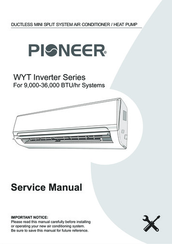
IntroductionInstallation ConsiderationsWARNING: Do not install the unit within 3 ft(0.9m) of fossil fuel burning heaters. Air intakealong the sides of this heat pump pool heatercould disturb the combustion process of theunit, and could cause damage or personal injury. Mount the unit on a level, sturdy base, preferablya concrete slab. The size of the base should be atleast 3 ft by 3 ft (0.9m x 0.9m) - slightly larger ifhurricane tie down brackets are installed. See pages8-10 for more details.WARNING: This pool/spa heat pump pool heateris an electromechanical machine that incorporatesa pressurized refrigerant gas in a sealed system.ONLY trained and qualified service personnel areauthorized to install or service this equipment.Without proper training and knowledge of suchequipment, any attempt to install or service the unitcould result in serious injury or even death.This manual contains important information on theuse, maintenance and troubleshooting of your newheat pump pool heater. This unit must be properlyinstalled, maintained and operated for optimal performance.CAUTION: The unit’s supporting base must behigh enough to keep it completely free of standingwater at all times.Situate the heat pump pool heater carefully to minimizeinstallation costs while providing maximum efficiencyof operation, and to allow adequate service access,as follows:This heat pump pool heater is an extremely efficient,economical machine designed specifically for swimming pool heating. It is similar in design and operationto a typical residential air conditioning system. The unitemploys a hermetic motor/compressor operating in arefrigeration cycle to extract heat from ambient air anddeliver it to the circulating pool water. As with all heat pump pool heaters, compared to othertypes of heaters such as gas or oil-fired, this heatpump pool heater has lower heating capacity on aBTUH/hr basis. As a result, it will be required to operate longer to accomplish the desired results. It may, atcertain times, operate as much as 24 hours per day.However, this should not be of concern to the owner,because the unit is designed to operate continuously.Even though it may operate continuously for manyhours, it will still heat the pool with greater economythan other types of fossil fuel heaters.For unrestricted air intake and service access,position each side of the unit at least 1 ft (30cm) from walls, pipes and other obstructions.WARNING: This unit is designed for outdoorinstallation; DO NOT install it in an enclosed areasuch as a shed or garage.Place a cover or blanket over the pool at night andother non-use periods. This will keep evaporation,the main cause of main heat loss, to a minimum, andwill greatly reduce pool heating costs. During warmerweather, the cover may be required only at night.NOTE: Hurricane tie down brackets, tie downscrews, 2 x union halves, 2 x 45-degree PVCelbows, the printed warranty and the I&O manual arelocated in an accessory box mounted on the palletbeside the heater inside the packaging. DO NOTthrow away without removing all components.6 This unit features an ‘up-flow’ discharge for quietoperation. Air is pulled up through the evaporatorcoil and discharged through the top grille. Allowat least 5 ft (1.5 m) clearance above the unit forunrestricted air discharge. DO NOT install the unitunder a porch or deck. Refer to Fig. 1. Recirculation of cold discharge air back into the evaporatorcoil will greatly reduce the unit’s heating capacityand efficiency. To minimize water piping, locate the unit as closeas possible to the existing pool pump and filter. Irrigation water should be directed away from theheat pump pool heater - irrigation water spray candamage the heat pump pool heater. Rain water run offs - the unit is designed to operate outdoors and can be exposed to rain. However, rain water run off falling directly onto the unitcan cause damage and/or shorten the life of yourunit. This may also void your warranty. Install raingutters or rain diverters on your roof if the unit isinstalled in a position where contact with rain runoff may occur.
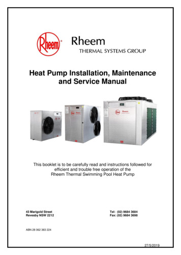
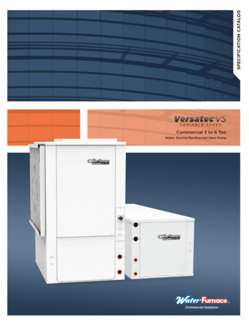
60” (1.52m) MIN3 FT(09.m)MINGASHEATERAIR FLOW OUT12”(0.3m)MINAIRFLOWINAIRFLOWINFig. 1: Installation Clearances It is important to keep the area next to the heatpump pool heater clear of shrubs, bushes andchemicals containers. They could prevent airfrom circulating fully through the heat pump poolheater, and will affect the operation of the heatpump pool heater or damage the heat pump poolheater. When installed in areas where freezing temperatures can be encountered, drain the water circuitto prevent possible freeze-up damage. Refer toFreeze Protection section on page 35 for properprocedures. If the location of the HPPH is below the water lineof the pool, the Water Pressure Switch (WPS)or Water Flow Switch (WFS) might need to beadjusted or an external WFS might be needed. For high wind installation requirements, refer tothe figures on page 8, 9 or 10 – depending onmodel size.Fig. 2: Base Design - HandlingNOTE: The base is designed with recessed areasto allow the use of hand trucks or lifting without thepossibility of pinching fingers as shown in Figure 2.7
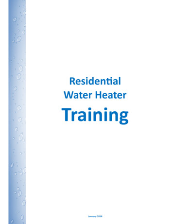
Fig. 3: Hurricane Tie Down Instructions – 24503000 PSI MIN.CONCRETE BYOTHERS, TYP.ANCHOR PERSCHEDULECONCRETE SLABBY OTHERS, TYP.UNIT HEIGHT31" MAXA&CN.T.S.ELEVATIONTIE-DOWN CLIPSA & C ARE SIMILAR ANDOCCUR ON OPPOSITEFACESUNIT BASEPANCONCRETE:(4" THICK MIN,3000 PSI MIN.)SUBSTRATEDCLIP ACLIP BNOTE: CHECK I&O MANUAL FORMINIMUM PAD DIMENSIONS ANDSCREW LENGTH (U.O.N)FRONT ISOMETRICDIM. 1DATUM FACECONTROLBOXCLIP DCLIP C4.50" MAX OFFSET FROM DATUM FACE24.50" MIN OFFSET FROM DATUM FACE25.25" MIN OFFSET FROM DATUM FACE13.00" MAX OFFSET FROM DATUM FACEDIM. 1DIM. 2DIM. 3DIM. 4PLANMIAMI TECH CLIP: 14GA (0.07")ASTM A653 Fu 90 KSI STEEL(CUTD8) OR 0.080" 5052-H32ALUMINUM (CUTDA8)FLORIDA APPROVAL FL#19731.1OR APPROVED EQUALSEE GENERAL NOTE 6TIE-DOWN CLIP OFFSETS:N.T.S.1.000"0.750"1.000"8.000"TIE-DOWN CLIP0.306"TYP.0.187"1.250"TIE-DOWN CLIP LAYOUTCLIP OFFSET DIMENSION SHALLBE TAKEN FROM THIS SIDE ONLYUNIT BASEPANINTERNAL POSTADJACENT TOCONTROL BOX(1)-1/4"Ø CARBON STEEL POWERS WEDGE BOLT , 2" EMBED TOCONCRETE, 3" MIN. EDGE DISTANCE, 3" MIN. SPACING TO ANYADJACENT ANCHOR.DESCRIPTIONANCHOR SCHEDULE:BUNIT BASEPANLOUVERPANEL,TYP.(2)-#10SMS PERCLIP, TYP.THESE ISOMETRICS ARE INTENDED FORDIAGRAMMATICAL PURPOSES ONLY.BACK ISOMETRICMECHANICAL UNITDCCONTROLCOVERUNITL29.75 ENGT"MHAXN.T.S.HIDTIT W AXUN 5" M729.N.T.S.CONCRETE SLABBY OTHERS, TYP.UNIT HEIGHT31" MAXMECHANICAL UNITBA18-GA ASTMA653 PAINTEDUNITL29.75 ENGT"MHAXDIM. 2HIDTIT W AXUN 5" M729.DIM. 30.313"DIM. 48Screws to attach brackets tounit are supplied with the unit- DO NOT use screws notspecified or provided by manufacturer. Screws are stainlesssteel #10 x 3/4" self drilling.Each bracket requires 4 screwsattached to the unit.Minimum pad dimensions are43-1/4" x 43-1/4" x 4" thick.
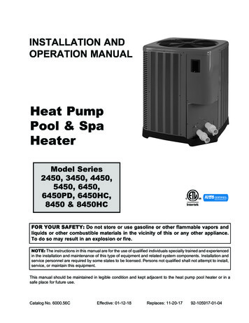
Fig. 4: Hurricane Tie Down Instructions – 3450 - 44503000 PSI MIN.CONCRETE BYOTHERS, TYP.ANCHOR PERSCHEDULECONCRETE SLABBY OTHERS, TYP.UNIT HEIGHT39" MAXCONCRETE SLABBY OTHERS, TYP.A&CUNIT BASEPAN(3)-#10SMS PERCLIP, TYP.CONCRETE:(4" THICK MIN,3000 PSI MIN.)SUBSTRATEDN.T.S.INTERNAL POSTADJACENT TOCONTROL BOXCLIP ACLIP BNOTE: CHECK I&O MANUAL FORMINIMUM PAD DIMENSIONS ANDSCREW LENGTH (U.O.N)FRONT ISOMETRICDIM. 1DATUM FACE29.00" MIN OFFSET FROM DATUM FACE13.00" MAX OFFSET FROM DATUM FACEDIM. 3DIM. 44.50" MAX OFFSET FROM DATUM FACE28.00" MIN OFFSET FROM DATUM FACEDIM. 2DIM. 1CONTROLBOXCLIP DCLIP CPLANMIAMI TECH CLIP: 14GA (0.07")ASTM A653 Fu 90 KSI STEEL(CUTD8) OR 0.080" 5052-H32ALUMINUM (CUTDA8)FLORIDA APPROVAL FL#19731.1OR APPROVED EQUALSEE GENERAL NOTE 6TIE-DOWN CLIP OFFSETS:N.T.S.1.000"0.750"1.000"8.000"TIE-DOWN CLIP0.306"TYP.0.187"1.250"TIE-DOWN CLIP LAYOUTCLIP OFFSET DIMENSION SHALLBE TAKEN FROM THIS SIDE ONLYUNIT BASEPANDCCONTROLCOVERUNITL33.75 ENGT"MHAXMECHANICAL UNITHIDTIT W AXUN 5" M7.33(1)-1/4"Ø CARBON STEEL POWERS WEDGE BOLT , 2" EMBED TOCONCRETE, 3" MIN. EDGE DISTANCE, 3" MIN. SPACING TO ANYADJACENT ANCHOR.DESCRIPTIONELEVATIONTIE-DOWN CLIPSA & C ARE SIMILAR ANDOCCUR ON OPPOSITEFACESN.T.S.UNIT HEIGHT39" MAXTHESE ISOMETRICS ARE INTENDED FORDIAGRAMMATICAL PURPOSES ONLY.BACK ISOMETRICANCHOR SCHEDULE:BUNIT BASEPANLOUVERPANEL,TYP.N.T.S.MECHANICAL UNITBA18-GA ASTMA653 PAINTEDUNITL33.75 ENGT"MHAXDIM. 2HIDTIT W AXUN 5" M7.33DIM. 30.313"DIM. 49Screws to attach brackets tounit are supplied with the unit- DO NOT use screws notspecified or provided by manufacturer. Screws are stainlesssteel #10 x 3/4" self drilling.Each bracket requires 4 screwsattached to the unit.Minimum pad dimensions are43-1/4" x 43-1/4" x 4" thick.
Fig. 5: Hurricane Tie Down Instructions – 5450 - 8450UNIT HEIGHT51" MAXBCONCRETE:(4" THICK MIN,3000 PSI MIN.)SUBSTRATEA&CUNIT BASEPAN(4)-#10SMS PERCLIP, TYP.N.T.S.(1)-1/4"Ø CARBON STEEL POWERS WEDGE BOLT , 2" EMBED TO CONCRETE, 3"MIN. EDGE DISTANCE, 3" MIN. SPACING TO ANY ADJACENT ANCHOR.DESCRIPTIONELEVATIONTIE-DOWN CLIPSDCLIP ACLIP BDIM. 1DATUM FACEN.T.S.30.00" MIN OFFSET FROM DATUM FACE31.00" MIN OFFSET FROM DATUM FACE13.00" MAX OFFSET FROM DATUM FACEDIM. 2DIM. 3DIM. 44.50" MAX OFFSET FROM DATUM FACETIE-DOWN CLIP OFFSETS:DIM. 11.000"TIE-DOWN CLIP0.306"TYP.0.187"Screws to attach brackets tounit are supplied with the unit- DO NOT use screws notspecified or provided by manufacturer. Screws are stainlesssteel #10 x 3/4" self drilling.Each bracket requires 4 screwsattached to the unit.Minimum pad dimensions are43-1/4" x 43-1/4" x 4" thick.CONTROLBOXCLIP DCLIP CAPPLICABLE MODELS:5450, 6450 & 8450PLANMIAMI TECH CLIP: 14GA (0.07") ASTM A653Fu 90 KSI STEEL (CUTD10) OR 0.080"5052-H32 ALUMINUM (CUTDA10).FLORIDA APPROVAL FL#19731.1OR APPROVED EQUALSEE GENERAL NOTE 6CCONTROL COVER1.250"0.750"1.000"10.000"0.313"TIE-DOWN CLIP LAYOUTCLIP OFFSET DIMENSION SHALLBE TAKEN FROM THIS SIDE ONLYUNIT BASEPANINTERNAL POSTADJACENT TOCONTROL BOXTHESE ISOMETRICS ARE INTENDED FORDIAGRAMMATICAL PURPOSES ONLY.A & C ARE SIMILARAND OCCUR ONOPPOSITE FACESUNIT BASEPANLOUVERPANEL,TYP.N.T.S.FRONT ISOMETRICMECHANICAL UNITBACK ISOMETRICDUNIT35. LENG75"TMA HXN.T.S.BCONCRETE SLABBY OTHERS, TYP.UNIT HEIGHT51" MAXMECHANICA
Installation Considerations Situate the heat pump pool heater carefully to minimize installation costs while providing maximum efficiency of operation, and to allow adequate service access, as follows: For unrestricted air intake and service access, position each side of the unit at lea