Transcription
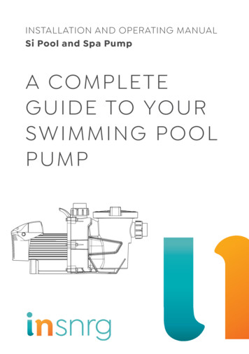
INSTALLATION AND OPERATING MANUALSi Pool and Spa PumpA COMPLETEGUIDE TO YOURSWIMMING POOLPUMP
CONGRATULATIONS ONPURCHASE YOUR INSNRGSWIMMING POOL PUMP.THIS MANUAL HAS BEEN CAREFULLY DEVELOPED TOGIVE YOU ALL THE INFORMATION YOU NEED TO GET THEBEST VALUE FROM YOUR PURCHASE.THE IMPORTANT BITS04SECTION 1:12SECTION 2: Health and Safety ConcernsInstallation requirementsHow to operate the major features of the unitThe importance of maintenanceIf you have a problem, what to trouble shoot before youcontact your professionalFinally, your entitlements under your product warranty.Insnrg have developed their product to provide you with theultimate experience and are sure you will be delighted with yourpurchase.Please note: This manual has been designed to cater forinstallation rules and codes in the USA, Canada and Australia.Specific rules and regulations for each country has beenhighlighted by the National flag of each country. Please ensureWe want you to be delightedSpecifications and DimensionsP u m p Lo c a t i o n s a n d C l e a ra n c e sInstallation TipsIt is important that you read through the manual to identify thekey areas you need to understand, particularly the following: We care about your safety17SECTION 3:Now to Have some FunStarting / Priming the Pump19SECTION 4:Oops, something not right ?MaintenanceWinterisingTro u b l e S h o o t i n gWa r ra n t yContact Detailsyou follow the installation rules specific to your country.23
SECTION 1WE CAREABOUT YOURSAFETYIMPORTANT WARNINGSWarning – Please read and followall instructions in this owner’smanual and on the equipment.Failure to follow instructions cancause severe injury and/or death.INSTALLERS: Insnrg highly recommend theinstallation of all their equipment by a suitablyqualified pool professional who will ensure yourhigh performance Insnrg products are installedto your local standards and codes to ensureoptimum safety and performance.4WARNINGThis appliance is not intended for use by persons (including children) withreduced physical, sensory or metal capabilities, or lack of experience andknowledge, unless have been given supervision or instruction concerning use ofthe appliance by a person responsible for their safety.WARNINGIf the supply cord is damaged, it must be replaced by the manufacturer, itsservice agent or similarly qualified persons in order to avoid a hazard.WARNINGFailure to remove pressure test plugs and/or plugs used in winterization of thepool/spa from the suction outlets can result in an increase potential for suctionentrapment as described above.WARNINGFailure to keep suction outlet components clear of debris, such as leaves, dirt,hair, paper and other material can result in an increase potential for suctionentrapment as described above.WARNINGSuction outlet components have a finite life, the cover/grate should beinspected frequently and replaced at least every ten years or if found to bedamaged, broken, cracked, missing, or not securely attached.WARNINGNever operate or test the circulation system at more than 50 PSI.WARNINGNever change the filter control valve position while the pump is running.5
CAUTIONAll components of the filtration system including Pumps, Filters, Heaters must bepositioned so to prevent being used as means of access to the pool by youngchildren. To reduce risk of injury, do not permit children to use or climb on thisproduct. Closely supervise children at all times.WARNING - HAZARDOUS PRESSUREPool and Spa water circulation systems operate under hazardous pressureduring start up, normal operation, and after pump shut off. Stand clear ofcirculation system equipment during pump start-up. Failure to follow safety andoperation instructions could result in violent separation of the pump housingand cover, and/or filter housing and clamp due to pressure in the system, whichcould cause property damage, severe personal injury, or death. Before servicingpool and spa water circulation systems, all system and pump controls must be inthe off position and filter manual relief valve must be in open position. Beforestarting system pump, all system valves must be set in a position that allowssystem water to return back to the pool. Do not change filter control valveposition whilst system pump is operating. Before starting system pump, fullyopen filter manual air relief valve. Do not close filter manual air relief valve untila steady stream of water (not air) is discharged.WARNINGThis pump is to be supplied by an isolating transformer or supplied througha residual current device (RCD) having a rated residual operating current notWARNINGElectrical ground all electrical equipment before connecting to electricalpower supply. Failure to ground all electrical equipment can cause seriousor fatal electrical shock hazard.WARNINGDo NOT ground to a gas supply line.WARNINGTo avoid dangerous or fatal electrical shock, turn OFF power to allelectrical equipment before working on electrical connectionsWARNINGFailure to bond all electrical equipment to pool structure will increase riskfor electrocution and could result in injury or death. To reduce the riskof electric shock, see installation instructions and consult a professionalelectrician on how to bond all electrical equipment. Also, contact alicensed electrician for information on local electrical codes for bondingrequirements.exceeding 30 mA.WARNING - RISK OF ELECTRIC SHOCKAll electrical wiring MUST be in conformance with applicable local codes,regulations, and the National Electric Code (NEC). Hazardous voltage can shock,burn, and cause death or serious property damage. To reduce the risk of electricshock, do NOT use an extension cord to connect unit to electric supply. Providea properly located electrical receptacle. Before working on any electricalequipment, turn off power supply to the equipment.WARNING6To reduce the risk of electric shock replace damaged wiring immediately.Locate conduit to prevent abuse from lawn mowers, hedge trimmers andother equipment.Notes to electrician: Use a solid copper conductor, size 8 orlarger. Run a continuous wire from external bonding lug to reinforcingrod or mesh. Connect a No. 8 AWG (8.4 mm2) [No. 6 AWG (13.3 mm2)for Canada] solid copper bonding wire to the pressure wire connectorprovided on the electrical equipment and to all metal parts ofswimming pool, spa, or hot tub, and metal piping (except gas piping),and conduit within 5 ft. (1.5 m) of inside walls of swimming pool, spa, orhot tub.IMPORTANT - Reference NEC codes for all wiring standardsincluding, but not limited to, grounding, bonding and other generalwiring procedures.7
WARNINGRisk of Electric Shock. Connect only to a branch circuit protected by aground-fault circuit-interrupter (GFCI). Contact a qualified electrician ifyou cannot verify that the circuit is protected by a GFCI.WARNINGRisk of Electric Shock . The electrical equipment must be connected onlyto a supply circuit that is protected by a ground-fault circuit-interrupter(GFCI). Such a GFCI should be provided by the installer and should betested on a routine basis. To test the GFCI, push the test button. The GFCIshould interrupt power. Push reset button. Power should be restored. Ifthe GFCI fails to operate in this manner, the GFCI is defective. If the GFCIinterrupts power to the electrical equipment without the test buttonbeing pushed, a ground current is flowing, indicating the possibility ofan electrical shock. Do not use this electrical equipment. Disconnectthe electrical equipment and have the problem corrected by a qualifiedservice representative before using.CAUTIONThis pump is intended for use with permanently-installed pools and maybe used with hot tubs and spas if so marked. Do not use with storablepools. A permanently-installed pool is constructed in or on the groundor in a building such that it cannot be readily disassembled for storage.A storable pool is constructed so that it is capable of being readilydisassembled for storage and reassembled to its original integrity.TYPES OF ENTRAPMENTHAZARDS:Suction Entrapment HazardSuction outlets and/or suction outlet covers which are, damaged,broken, cracked, missing, or unsecured can cause severe injuryand/or death due to the following entrapment hazards:Hair Entrapment- Hair can become entangled in suction outletcover.Limb EntrapmentA limb inserted into an opening of a suction outlet or suctionoutlet cover that is damaged, broken, cracked, missing, or notsecurely attached can result in a mechanical bind or swelling ofthe limb.Body Suction EntrapmentA negative pressure applied to a large portion of the body or limbscan result in an entrapment.Evisceration/ DisembowelmentA negative pressure applied directly to the intestines throughan unprotected suction outlet or suction outlet cover which is,damaged, broken, cracked, missing, or unsecured can result inevisceration/ disembowelment.Mechanical EntrapmentThere is potential for jewellery, swimsuit, hair decorations, finger,toe or knuckle to be caught in an opening of a suction outletcover resulting in mechanical entrapment.89
TO REDUCE THE RISKOF ENTRAPMENTHAZARDS: 10When outlets are small enough to be blocked by a person, aminimum of two functioning suction outlets per pump mustbe installed. Suction outlets in the same plane (i.e. floor orwall), must be installed a minimum of 1 metre (3 Feet) apart, asmeasured from near point to near point. Dual suction fittings shall be placed in such locations anddistances to avoid “dual blockage” by a user. Dual suction fittings shall not be located on seating areas oron the backrest for such seating areas. The maximum water velocity through the suction outletassembly and its cover for any suction. Outlet must not exceed the suction fitting assembly and it’scover’s maximum design flow rate. The suction outlet (drain)assembly and its cover must comply with the latest version ofANSI/ASME A112.19.8, the standard for Suction Fittings For Usein Swimming Pools, Wading Pools, Spas, and Hot Tubs, or itssuccessor standard, ANSI/APSP-16. Never use Pool or Spa if any suction outlet component isdamaged, broken, cracked, missing, or not securely attached. Replace damaged, broken, cracked, missing, or not securelyattached suction outlet components immediately. In addition to the above instructions for two or moresuction outlets per pump, they must be installed inaccordance with latest ASME, APSP Standards and CPSCguidelines, and follow all National, State, and Local codesapplicable. Installation of a vacuum release or vent system, whichrelieves entrapping suction, is recommended11
WE WANT YOU TO BEDELIGHTED WITH YOURPURCHASE, CORRECTINSTALLATION WILL PROLONGLIFE AND MAXIMISE THEPERFORMANCE OF THIS UNIT.Congratulations on yourpurchase of an Insnrg Pump.SPECIFICATIONS ANDDIMENSIONS8765F371mm (14.6in)SECTION 2E).9inD331mm(13.0in)mm(28733MODELSi 200Si 300Si 400Si 500VOLTS230230230230CINPUT WATTS .58.3FLOW RATE(@ 8m/h)200FULL LOAD AMPS4.5Your Si Single Speed PumpBSi PUMP FLOWA CHARThas been designed andSi 200manufactured to provideSi 3008Si4007Si50065you with years of troublefree operation if installedand operated correctly. Thefollowing guidelines needto be adhered to to gain thebest performance from yourswimming pool pump.12Insnrg highlyrecommend theuse of qualifiedservice techniciansto ensure the bestperformance aswell as the healthand safety of yourfamily.Pump maximum total head is 21 metres13
PUMP LOCATION ANDCLEARANCESFor optimal performance of your new Insnrg Pump werecommend installing the pump within 30 cm (1 ft) above waterlevel. If the pool pump needs to be elevated more than 1 m(3 ft) above the water level of the pool, then a check valve isrecommended on the suction line to the pump.If the pump is located below water level, isolation valves must beinstalled on both the suction and return lines to prevent the backflow of pool water during any routine or required servicing.For electrical connection, install the pump such that anydisconnecting means and/or junction boxes are within sight ofthe pump and at least 1.5 m (5 ft) horizontally from the edge ofthe pool and/or spa. Choose a location that will minimize theamount of elbows required in the PVC piping.NOTE: In Canada, the minimum distance maintained from theedge of the pool and/or spa as noted above must be 3 m (10 ft),as required by the Canadian Electrical Code (CEC, CSA C22.1).The pump must be placed on a solid foundation that will notvibrate. To further reduce the possibility of vibration noise, boltthe pump to the foundation, or place it on a rubber mat.The pump foundation must have adequate drainage to preventthe motor from getting wet. The pump has been designed foruse outdoors, however, to prolong the life of the pump anyprotection from the rain and sun will ensure a great result.All motors generate heat when in operation, therefore, pleaseensure that the motor is installed with adequate ventilationaround the motor. Do not install the motor directly onto a wallor fence, the Fan at the back requires at least 2” (50mm) of spaceto generate enough air-flow.Provide access for future service by leaving a clear area aroundthe pump. Allow plenty of space above the pump to remove thelid and basket for cleaning.If the equipment is under cover, provide adequate lighting.1415
TIPS ON INSTALLATIONFOR BEST RESULTS1. Minimise the amount of PVC Pipe and Fittings through yourfiltration system. The longer the pipe and the greater theamount of fittings the more pressure is built into the system andthe harder the Pump has to operate. This will eventually reducethe lifespan of the Pump as well as costing you more energy tooperate.2. Always use minimum of 50mm (2”) PVC Pipe on the Inlet of thePump.3. Where possible use minimum of 50mm (2”) PVC Pipe on theOutlet of the Pump.4. Keep Pump clear of any debris, rubbish, other equipment,chemicals, walls etc. It is important that the circulation ofair around the motor is clear to help reduce the runningtemperature and extend the lifespan of the pump.SECTION 3HAVE FUN ANDGET THE MOSTOUT OF YOURPURCHASENow that your Insnrg Pump is installed andoperating, it is important to understand how tokeep it in the best condition and give you the bestresults for many years to come.5. Ensure that if any other equipment exists in your filtrationsystem (ie Filter, Heater, Sanitiser etc) that you have thoroughlychecked that the Pump Flow rate does not exceed the maximumflow rates for the other equipment. If it is not suitable, this willaffect the performance of the Pump and the other equipmentand most likely void any warranty claims on all items.1617
STARTING /PRIMING THE PUMPOnce your Insnrg Si Single Speed Pump has been installed, it is nowtime to turn on and fill with water, a process known as ‘priming’ thePump. If the Pump is not primed correctly it could cause the Pump to‘run dry’.Note: Running the pump dry could cause a loss of pressure, resulting indamage to the pump case, impeller and seal.Firstly, check where your Pump is installed in relation to the pool waterlevel. If below the water level of the pool you need to check that theisolation valves on both the suction and return lines are returned tothe ‘OPEN’ position. They must be OPEN before you start operating thePump.The pump strainer pot must be filled with water before the pump isinitially started. Your Insnrg Pump has a unique feature that enables thePump to be filled to a higher level, making the priming process quickerand easier. Follow the steps below to prime the pump:SECTION 4OOPS,SOMETHING’SNOT RIGHT?Maintenance, Trouble Shooting,Replacement Parts, Warranty &Contact Section1. Remove the pump lid and locking ring.2. Fill the pump strainer pot with water, generally use a Bucket and/orGarden Hose.3. Reassemble the pump lid and locking ring onto the strainer pot. Thepump is now ready to prime.4. Open the air relief valve on the filter, and stand clear of the filter.5. Turn on the pump.6. When water comes out of the filter air relief valve, close the valve.The system should now be free of air and recirculating water to andfrom the pool.1819
MAINTENANCE PLANYour new Si Single Speed Pump isone of the hardest working itemsin your household. It is designedto withstand harsh outdoorconditions and withstand highvelocity water with chemicals.Some of these parts will wearin the normal course of useand require regular checks andmaintenance. A well thought outpro-active maintenance schedulewith identify faults early andextend the lifespan of your pump.WHEN?WeeklyQuarterlyWHAT ARE YOULOOKING FOR?HOW CAN YOU FIX?Is it important to protect your Si Single Speed Pump from freezingwater conditions. As water freezes it expands and that can causethe internals of the Pump to break under the intense pressure ofexpanding water. It is our to you to monitor temperatures and takethe following actions:1. In mild climate areas, when temporary freezing conditions mayoccur, run your pump and filtering equipment all night to maintainwater circulation and prevent freezing.2. If freezing conditions are expected, take the following steps toreduce the risk of freeze damage. Freeze damage is not coveredunder warranty.Check and EmptyBasketEmpty Leaves and other debrisCheck all GasketsIsolate and turn off the Pump.Remove all Gaskets and turn over.You can also apply a silicon basedgrease to extend the life. If dry,then contact your local pool professional to replace.Check around theunit for leaves/debris or signs offlooding.Replace any debris that is restricting air circulation around thePump. If in a flood prone location,rectify.Check for any Insects/Ants etcIt is a good practice to use a goodquality surface spray around yourequipment. Make sure all units areturned off and then spray aroundall units to eliminate any insect/ants etcCheck for any leaks20To protect against extremes oftemperature, your unit is ventedto allow expensive electronics tocool. Ants and some insects areoften attracted to the warmer,dry environment inside theenclosure. We recommend that,with power turned off, you spraya surface insecticide on thesurfaces surrounding the controlto prevent ant and insect ingress.Repeat every three months or asnecessary.WINTERISATIONIf you notice any water leakingfrom the pump. Check gasketsfirst and reseal. If continues,contact your local poolprofessional to assess and rectify.To prevent freeze damage follow the procedures listed below:1. Shut off electrical power for the pump at the house circuitbreaker. 2. Drain the water out of the pump housing by removing the twothumb-twist drain plugs from the housing. Store the plugs in thepump basket.3. Cover the motor to protect it from severe rain, snow and ice.Once the freezing conditions are finished, it is important to reversethe above procedure and prime the pump for operation.21
8TROUBLESHOOTINGThe chart below identifies some of the main issues you mayencountered with your pump. This should assist with the majority ofproblems. Insnrg highly recommends regular checks and maintenanceof your swimming pool equipment by a qualified pool professional.This will extend the life of your equipment and give you the bestperformance.FE76543REPLACEMENT PARTSOFPUMP191D2WHAT IS THE PROBLEM? WHAT YOU CAN DO ABOUT IT? Check that any Valves on the Suction and Return lines are openPump will not Prime Pump Gasket is damagedToo much Air in the PumpBasket Debris in Diffuser or Impellor22 Check that Lid and Gasket is correctly seated and sealedCheck Unions and Gaskets on Suction and Return side of the Pumpare correctly seated and sealedFill Wet End of Pump with water as high as possibleCheck that water level in the Pool is high enough that water is drawinginto the SkimmerRemove any suction cleaners from the Skimmer BoxImportant that the Gasket can fully seal and eliminate any air cominginto the Pump. Replace if damaged.Check that any Valves on the Suction and Return lines are
2 3 congratulations on purchase your insnrg swimming pool pump. this manual has been carefully developed to give you all the information you need to get the