Transcription
ADTRAN Operating System (AOS)Configuring OSPFv2 in AOSConfiguration Guide61200870L1-29.3DJune 2020
To the Holder of this DocumentConfiguring OSPFv2 in AOSTo the Holder of this DocumentThis document is intended for the use of ADTRAN customers only for the purposes of the agreement underwhich the document is submitted, and no part of it may be used, reproduced, modified or transmitted in anyform or means without the prior written permission of ADTRAN.The contents of this document are current as of the date of publication and are subject to change withoutnotice.Trademark Information“ADTRAN” and the ADTRAN logo are registered trademarks of ADTRAN, Inc. Brand names and productnames included in this document are trademarks, registered trademarks, or trade names of their respectiveholders.Disclaimer of LiabilityThe information or statements given in this document concerning the suitability, capacity, or performance of thementioned hardware or software products are given “as is”, and any liability arising in connection with suchhardware or software products shall be governed by ADTRAN’s standard terms and conditions of sale unlessotherwise set forth in a separately negotiated written agreement with ADTRAN that specifically applies to suchhardware or software products.To the fullest extent allowed by applicable law, in no event shall ADTRAN be liable for errors in this documentfor any damages, including but not limited to special, indirect, incidental or consequential, or any losses, suchas but not limited to loss of profit, revenue, business interruption, business opportunity or data, that may arisefrom the use of this document or the information in it.Copyright 2020 ADTRAN, Inc.All Rights Reserved.261200870L1-29.3D
Configuring OSPFv2 in AOSRevision HistoryRevision HistoryRev D61200870L1-29.3DJune 2020Updated document format and corrected IP addresses inexample illustration.3
Table of ContentsConfiguring OSPFv2 in AOSTable of ContentsConfiguring OSPFv2 in AOS. . . . . . . . . . . . . . . . . . . . . . . . . . . . . . . . . . . . . . . . . . . . . . . . 5OSPFv2 Overview . . . . . . . . . . . . . . . . . . . . . . . . . . . . . . . . . . . . . . . . . . . . . . . . . . . . . . . . 5Link-State vs. Distance-Vector Routing Protocols . . . . . . . . . . . . . . . . . . . . . . . . . . . . . . . . . . . . 5OSPFv2 Network Topologies . . . . . . . . . . . . . . . . . . . . . . . . . . . . . . . . . . . . . . . . . . . . . . . . . . . . 6Hello Protocol . . . . . . . . . . . . . . . . . . . . . . . . . . . . . . . . . . . . . . . . . . . . . . . . . . . . . . . . . . . . . . . . 9OSPFv2 Link-State Advertisement . . . . . . . . . . . . . . . . . . . . . . . . . . . . . . . . . . . . . . . . . . . . . . . 10OSPFv2 Tables and Databases . . . . . . . . . . . . . . . . . . . . . . . . . . . . . . . . . . . . . . . . . . . . . . . . . 11OSPFv2 Router Types . . . . . . . . . . . . . . . . . . . . . . . . . . . . . . . . . . . . . . . . . . . . . . . . . . . . . . . . 13OSPFv2 Area Types . . . . . . . . . . . . . . . . . . . . . . . . . . . . . . . . . . . . . . . . . . . . . . . . . . . . . . . . . . 14Importance of Addressing Schemes . . . . . . . . . . . . . . . . . . . . . . . . . . . . . . . . . . . . . . . . . . . . . . 15OSPFv2 and VRF . . . . . . . . . . . . . . . . . . . . . . . . . . . . . . . . . . . . . . . . . . . . . . . . . . . . . . . . . . . . 15OSPFv2 Redistribution . . . . . . . . . . . . . . . . . . . . . . . . . . . . . . . . . . . . . . . . . . . . . . . . . . . . . . . . 16Hardware and Software Requirements and Limitations . . . . . . . . . . . . . . . . . . . . . . . . 16Configuring OSPFv2 in AOS. . . . . . . . . . . . . . . . . . . . . . . . . . . . . . . . . . . . . . . . . . . . . . . 16Accessing the CLI . . . . . . . . . . . . . . . . . . . . . . . . . . . . . . . . . . . . . . . . . . . . . . . . . . . . . . . . . . . .Configuring OSPFv2 Global Settings . . . . . . . . . . . . . . . . . . . . . . . . . . . . . . . . . . . . . . . . . . . . .Configuring OSPFv2 Redistribution Settings . . . . . . . . . . . . . . . . . . . . . . . . . . . . . . . . . . . . . . .Configuring OSPFv2 Interface Settings . . . . . . . . . . . . . . . . . . . . . . . . . . . . . . . . . . . . . . . . . . .Using Route Maps with OSPFv2. . . . . . . . . . . . . . . . . . . . . . . . . . . . . . . . . . . . . . . . . . . . . . . . .1617212326OSPFv2 Configuration Examples. . . . . . . . . . . . . . . . . . . . . . . . . . . . . . . . . . . . . . . . . . . 30Example 1: Single Area OSPF with Default Route Propagation and Static Route Redistribution 30Example 2: Multi-VRF OSPFv2 CLI Configuration Example. . . . . . . . . . . . . . . . . . . . . . . . . . . . 32Example 3: Redistributing BGP into OSPFv2 . . . . . . . . . . . . . . . . . . . . . . . . . . . . . . . . . . . . . . . 34OSPFv2 Command Summary . . . . . . . . . . . . . . . . . . . . . . . . . . . . . . . . . . . . . . . . . . . . . . 36Troubleshooting OSPFv2 . . . . . . . . . . . . . . . . . . . . . . . . . . . . . . . . . . . . . . . . . . . . . . . . . 44OSPFv2 Show Commands . . . . . . . . . . . . . . . . . . . . . . . . . . . . . . . . . . . . . . . . . . . . . . . . . . . . . 44OSPFv2 Clear Commands . . . . . . . . . . . . . . . . . . . . . . . . . . . . . . . . . . . . . . . . . . . . . . . . . . . . . 49OSPFv2 Debug Commands . . . . . . . . . . . . . . . . . . . . . . . . . . . . . . . . . . . . . . . . . . . . . . . . . . . . 49Warranty and Contact Information. . . . . . . . . . . . . . . . . . . . . . . . . . . . . . . . . . . . . . . . . . 50Warranty . . . . . . . . . . . . . . . . . . . . . . . . . . . . . . . . . . . . . . . . . . . . . . . . . . . . . . . . . . . . . . . . . . . 50Contact Information. . . . . . . . . . . . . . . . . . . . . . . . . . . . . . . . . . . . . . . . . . . . . . . . . . . . . . . . . . . 50461200870L1-29.3D
Configuring OSPFv2 in AOSConfiguring OSPFv2 in AOS1. Configuring OSPFv2 in AOSThis document explains the advantages of the Open Shortest Path First version 2 (OSPFv2) protocol over adistance-vector routing protocol such as Routing Information Protocol (RIP), describes the key componentsnecessary to implement OSPFv2, discusses the types of networks in which OSPFv2 is implemented, andgives details on topics such as Hello packets, link-state advertisements (LSAs), tables and databases, routertypes, and areas. In addition, this guide provides configuration instructions for OSPFv2 globally and perinterface on ADTRAN Operating System (AOS) products, an OSPFv2 configuration example, andtroubleshooting information.2. OSPFv2 OverviewOSPFv2 (version 1 was never implemented) is a powerful alternative to RIP, superior to RIP in many ways,but it makes more demands on router resources and requires more planning to implement. The next sectionof this configuration guide delineates the differences between OSPFv2 and RIP and explains both thebenefits and negative aspects of OSPFv2.Link-State vs. Distance-Vector Routing ProtocolsBasic RIP configuration and setup are well known. RIP looks at Hop Count to determine its cost for thenetwork. Every 30 seconds, RIP propagates its routing table out all interfaces configured for RIP. As a result,on larger networks RIP is very chatty. Although RIP has certain mechanisms to handle routing loops (splithorizon and split horizon with poison reverse), it does not handle redundant paths gracefully. In someinstances, RIP's convergence time causes the network to be down for an extended time while trying tore-converge the network.Because of these issues, a link-state protocol such as OSPFv2 may be a better solution than RIP in largenetworks (links that consist of more than 15 hops) and in significantly redundant networks. This guidedescribes how OSPFv2 solves these RIP issues.OSPFv2 was designed to address RIP's shortcoming of offering only a hop count metric. Unlike RIP, OSPFv2is a link-state routing protocol, which means that changes in routing are based on the status and speeds ofthe physical links. In addition, changes are immediately propagated to every router on the network.When an OSPFv2 router is first activated, it uses OSPFv2’s Hello protocol (for more information refer to HelloProtocol on page 9) to discover any connected neighboring routers. It then exchanges link-state informationwith these routers in the form of LSAs. Each router creates an LSA database that consists of every OSPFinterface, the corresponding neighbor, and a metric representing the speed of the interface. Each router thenuses LSAs to pass this information along to each neighboring router. Each router passes all received LSAs toall its other neighbors.The link-state database is distinct from the routing table. From the link-state database information, eachrouter calculates a path to every destination on the network, building a tree with itself at the root. Thiscomprises its shortest path first (SPF) tree, which forms the basis of the routing table. The routers exchangeLSAs every 30 minutes, unless there is a change in network topology. If an interface goes down, for example,the information is propagated across the network at once. If there is a redundant path, the convergence willlast as long as it takes to recalculate the SPF tree and update the routing tables. This can happen in a fewseconds or less, depending on the size of the network. Because of these calculations, routers runningOSPFv2 require more CPU resources. Frequent flooding of LSAs may also cause problems on wide areanetwork (WAN) links.OSPFv2 compensates for increased CPU and memory demands by dividing the network into separate,hierarchical domains, called areas. Routers exchange LSAs only with other routers in their own areas. Thereis also a backbone area known as Area 0. All areas must be adjacent to Area 0. A border between two areasis defined on an area border router (ABR). ABRs have at least one interface in Area 0 and one interface inanother non-backbone area. The best designed OSPFv2 networks contain contiguous networks to each area61200870L1-29.3D5
OSPFv2 OverviewConfiguring OSPFv2 in AOSthat can be summarized on the backbone through variable length subnet masks (VLSMs). This makes itpossible to summarize multiple networks in one routing table entry.Because routers within the same area share the same information, they have identical topological databases.When two neighboring routers are synchronized, the routers are said to be adjacent. When network topologychanges, adjacent routers send LSAs to provide information on a router's adjacencies or to inform otherswhen a router's state changes. By comparing established adjacencies to link-states, failed routers can bedetected quickly and the network's topology can be altered appropriately.Where RIP is unable to consider the speed of interfaces when determining the best path through the network,OSPFv2 addresses this by considering a cost that is derived by the speed of the interface. However, since theformula for determining the cost is not standardized, the default settings will vary.The OSPFv2 protocol was developed by the OSPFv2 working group of the Internet Engineering Task Force.It is expressly designed for the Transmission Control Protocol (TCP)/IP Internet environment and includesexplicit support for Classless Inter-Domain Routing (CIDR) and the tagging of externally derived routinginformation. OSPFv2 also provides for the authentication of routing updates, and utilizes IP multicast whensending/receiving the updates.The following table summarizes the differences between link-state and distance-vector routing protocols.Table 1. Distance-Vector versus Link-StateDistance-VectorLink-StateSends its entire routing table at periodic intervals outof all interfaces (typically, this is based in seconds). Italso sends triggered updates to reflect changes in thenetwork.Sends incremental updates when a change is detected.OSPFv2 sends summary information every 30 minutes,regardless of whether incremental updates have beensent in that same time.Typically involves updates sent using a broadcastaddress to everyone on the link.Typically involves updates sent to those routersparticipating in the routing protocol domain via amulticast address.Uses a metric based on distance of the remotenetwork from the router.Is capable of using a complex metric, referred to byOSPFv2 as cost.Has knowledge of the network based on informationlearned from its neighbor.Has knowledge of the network based on informationlearned from every router in the area.As mentioned previously, a neighbor in OSPFv2 is a router that shares the same network link (this is thesame physical segment), and a router running OSPFv2 discovers its neighbors and adjacencies by sendingHello packets every 10 seconds. The Hello packet has a source address of the router and a multicastdestination address set to ALLSPFRouters: 224.0.0.5. The multicast address 224.0.0.6 is used forcommunication to a designated router (DR) or backup designated router (BDR). The type of network mediaused determines how the Hello protocol functions and how OSPFv2 builds its neighbor. The following sectiondescribes OSPFv2 network topologies.OSPFv2 Network TopologiesOSPFv2 can be used in the following network topologies: Broadcast multi-access Point-to-point Point-to-multipoint Non-broadcast multi-access (NBMA) Virtual links661200870L1-29.3D
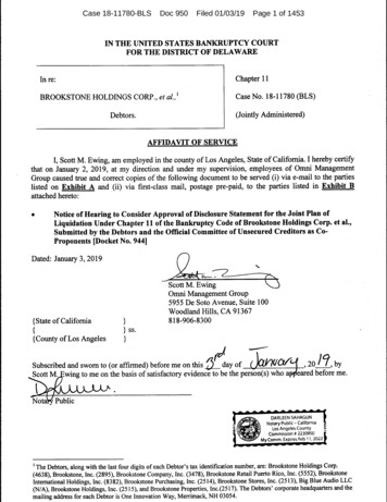
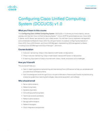
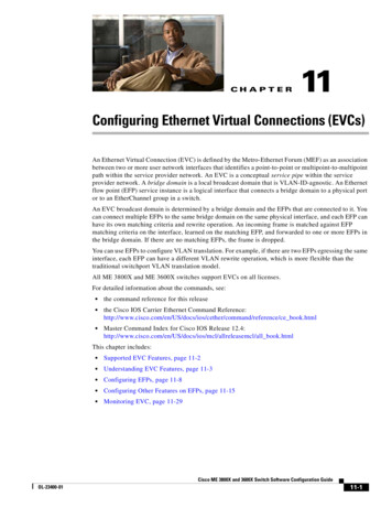
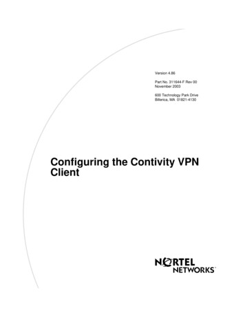
Configuring OSPFv2 in AOSOSPFv2 OverviewBroadcast Multi-accessThis network topology is used in local area networks (LANs) such as Ethernet, token ring, or fiber distributeddata interface (FDDI). OSPFv2 sends out multi-access traffic. A DR and a BDR are elected. (These two typesof routers will be discussed later in this document.) Each pair of routers on a broadcast network is assumed tobe able to communicate directly. Networks supporting many (more than two) attached routers use a singlephysical message to all the attached routers (broadcast). Neighboring routers are discovered dynamically onthese networks using OSPFv2's Hello protocol. The Hello protocol itself takes advantage of the broadcastcapability. The OSPFv2 protocol makes further use of multicast capabilities, if they DesignatedrouterFigure 1. Broadcast Multi-access Network TopologyPoint-to-PointThis topology is used when only one other router is directly connected to the transmitting or receivinginterface. A typical example of this is a serial line. OSPFv2 has no need of a DR or BDR in this scenario.Network traffic uses the multicast address for OSPFv2 AllSPFRouters 224.0.0.5.Figure 2. Point-to-Point Network TopologyPoint-to-MultipointPoint-to-multipoint topology features a single interface that connects to many destinations. The underlyingnetwork treats the network as a series of point-to-point circuits and replicates LSA packets for each circuit.The addressing of network traffic, again, is multicast. There is no DR or BDR election. This technology usesone IP subnet. According to the RFC, there are only two types of non point-to-point networks:61200870L1-29.3D7
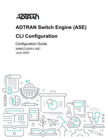
OSPFv2 OverviewConfiguring OSPFv2 in AOSpoint-to-multipoint and NBMA. (Cisco has a non-broadcast implementation of point-to-multipoint. The RFConly cites broadcast point-to-multipoint networks.)Figure 3. Point-to-Multipoint Network TopologyNon-broadcast Multi-accessNon-broadcast multi-access (NBMA) networks, which are not configurable on AOS devices, includemultipoint or access networks such as Frame Relay, X.25, and Asynchronous Traffic Mode (ATM). Broadcastmessages are turned off by default. Neighbor tables must be created manually. Networks supporting many(more than two) routers but having no broadcast capability are considered NBMA networks. Neighboringrouters are maintained on these networks using OSPFv2’s Hello protocol. However, due to the lack ofbroadcast capability, some configuration information may be necessary to aid in the discovery of neighbors.(A separate neighbor command is implemented.) On non-broadcast networks, OSPFv2 protocol packets thatare normally multicast need to be sent to each neighboring router, in turn. Frame Relay is an example of anon-broadcast network.Frame RelayorATMFigure 4. Non-broadcast Multi-access Network TopologyNon-broadcast networks are referred to as NBMA networks or point-to-multipoint networks, depending onOSPFv2's mode of operation over the network. The first mode, called non-broadcast multi-access or NBMA,simulates the operation of OSPFv2 on a broadcast network. The second mode, called point-to-multipoint,treats the non-broadcast network as a collection of point-to-point links.861200870L1-29.3D
Configuring OSPFv2 in AOSOSPFv2 OverviewVirtual LinkA virtual link topology is a virtual connection that tunnels through the network. The OSPFv2 network traffic issent in unicast datagrams across these links. There are three scenarios for the connection: Two backbone areas that need to be combined into one large area 0.0.0.0 (possibly, two independentOSPFv2 networks are combined). This is a virtual connection to a remote area that does not have any connections to the backbone (area0.0.0.0). The area is critical to the company and an extra link has been configured for redundancy.Hello ProtocolA link-state routing protocol develops a relationship with a neighbor router: one that is on the same physicalnetwork. The two routers must also have the same subnet mask and the same hello timers. The routingprotocol develops and maintains a relationship by sending a simple message, known as the Hello protocol,across the medium. This Hello protocol is used by OSPFv2 routers to advertise themselves on the networkwhen they first join and to form relationships with other OSPFv2 routers. This relationship (the neighborrelationship) is maintained as long as the simple message (Hello protocol) is received. If it is not receivedbefore the dead timer, the neighbor is determined to be unavailable.Table 2. Hello Protocol TimerNetwork TypeHello TimerDead TimerFrame Relay - NBMA30 seconds120 secondsFrame Relay - Point-to-Point10 seconds40 secondsEthernet - Broadcast10 seconds40 secondsStreamlined communications result because, after the topological databases are synchronized, incrementalupdates are sent to the neighbors as soon as a change is perceived, as well as every 30 minutes.Adjacencies created between neighbors control the distribution of the router protocol packets. Adjacenciesand neighbor relationships result in a much faster convergence of the network than can be achieved by RIPversion 1.61200870L1-29.3D9
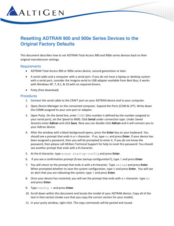
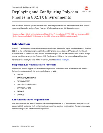
OSPFv2 OverviewConfiguring OSPFv2 in AOSOSPFv2 Link-State AdvertisementLSAs are link-state protocol packets that contain information about neighbors and path costs. LSAs are usedby the receiving router to maintain their routing tables. The following figure shows LSAs in action.Router andNetworkLSAsExternal and Area 4Summary LSAsExternal andArea 3 LSAsRouter and NetworkLSAsFigure 5. OSPFv2 Link-State AdvertisementThe table below describes LSA types.Table 3. LSA TypesLSA Type10Routing Table EntryDescriptionType 1 - RouterOThis is generated by each router, listing all thelinks to which it is connected, their status, andtheir cost. It is propagated within the area.Type 2 - NetworkOThis is generated by the DR on a multi-accessLAN to the area.Type 3 - SummaryIAThis LSA includes the networks or subnets withinan area that may have been summarized andthat are sent into the backbone and betweenABRs.Type 4 - ASBR-SummaryIAThis LSA is sent to the autonomous systemboundary router (ASBR) from the ABR to allowrouters to calculate the routing path for externaland NSSA LSAs that are generated from therouter that the ASBR-Summary describes. (Asper RFC2328 section 12.4.3.1 these are notallowed in stub areas or totally stubby areas.)61200870L1-29.3D
Configuring OSPFv2 in AOSOSPFv2 OverviewTable 3. LSA Types (Continued)LSA TypeRouting Table EntryDescriptionT
Hello packets every 10 seconds. The Hello packet has a source address of the router and a multicast destination address set to ALLSPFRouters: 224.0.0.5. The multicast address 224.0.0.6 is used for communication to a designated router (DR) or backu