Transcription
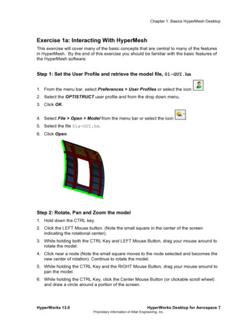
Chapter 1: Basics HyperMesh DesktopExercise 1a: Interacting With HyperMeshThis exercise will cover many of the basic concepts that are central to many of the featuresin HyperMesh. By the end of this exercise you should be familiar with the basic features ofthe HyperMesh software.Step 1: Set the User Profile and retrieve the model file, 01-GUI.hm1. From the menu bar, select Preferences User Profiles or select the icon.2. Select the OPTISTRUCT user profile and from the drop down menu.3. Click OK.4. Select File Open Model from the menu bar or select the icon.5. Select the file 01a-GUI.hm.6. Click Open.Step 2: Rotate, Pan and Zoom the model1. Hold down the CTRL key.2. Click the LEFT Mouse button. (Note the small square in the center of the screenindicating the rotational center).3. While holding both the CTRL Key and LEFT Mouse Button, drag your mouse around torotate the model.4. Click near a node (Note the small square moves to the node selected and becomes thenew center of rotation). Continue to rotate the model.5. While holding the CTRL Key and the RIGHT Mouse Button, drag your mouse around topan the model.6. While holding the CTRL Key, click the Center Mouse Button (or clickable scroll wheel)and draw a circle around a portion of the screen.HyperWorks 13.0HyperWorks Desktop for Aerospace 7Proprietary Information of Altair Engineering, Inc.
Chapter 1: Basics HyperMesh Desktop7. This will zoom into the region surrounded by the drawn circle.8. While holding the CTRL Key rotate the scroll wheel forward to Zoom Out and backwardto Zoom In.9. While holding the CTRL Key click the middle mouse button/scroll wheel to “fit” the modelto the screen.Step 3: Use the Model Browser to control visualization1. Press F on the keyboard to “fit” the model to the screen. If it does not work, click in thegraphics window and then press F.2. Make sure the Model Browser tab is active.3. Expand the Components category by clicking the next to it. This will list all of thecomponents in the model.4. Using the Geometryand ElementsIcons, turn on and off components.8 HyperWorks Desktop for AerospaceProprietary Information of Altair Engineering, IncHyperWorks 13.0
Chapter 1: Basics HyperMesh Desktop5. Using the Show/Hide Buttonturn off and on components in the graphics window.Right click to hide a component and left click in the area of a hidden component to see aghost image of the hidden component. Releasing the button reveals the component.6. Using the Isolate Button, right click on a component in the graphics window toisolate it (turn off all other components) and left click on a hidden component to see aghost image of the hidden component. Releasing the button isolates the selectedcomponent.7. Use the global controlsto turn on, off and reverse all of the components.8. Highlight components using the Left Mouse Button in the Graphics Area, and note howthe Global Controls now only affect the highlighted components.9. Use the icon (Both options.) to switch the global controls between the Geometry, Elements and10. Review the other Model Browser Views:a.Component ViewThis view is highly useful when working solely with components as none of theother collectors are shown in the view. This view contains all of the visibilitycontrol and right click functions of the Model View. Additionally it adds fieldsthat show the mesh and geometry shading as well as the property and materialapplied to each component.Currently there aren’t any material or properties assigned, but expand thebrowser area to see what is available in this view.HyperWorks 13.0HyperWorks Desktop for Aerospace 9Proprietary Information of Altair Engineering, Inc.
Chapter 1: Basics HyperMesh Desktopb.Property ViewThis view allows the user to view all of the properties in the model and color theentities on the screen by their assigned property. The visibility controls as wellas all right click extended functionality work with this view as well.c.Material ViewThis view allows the user to view all of the materials in the model and color theentities on the screen by their assigned material. The visibility controls as wellas all right click extended functionality work with this view as well.10 HyperWorks Desktop for AerospaceProprietary Information of Altair Engineering, IncHyperWorks 13.0
Chapter 1: Basics HyperMesh Desktop11. Return to the Model View and use the right click Extended Menu to try the followingfunctions:a. Create a new componentb. Rename a componentc. Delete a componentd. Show/Hide a componente. Isolate a componentf.Isolate Only a component (see if you can figure out the difference betweenIsolate and Isolate Only)g. Right click on a color and change the color of a component.Step 4: Working with Collectors1. Right click in the Model Browser and select Create Component.2. Name it Fuselage.3. In the Entity Editor, select a color.The new collector has been created and now we will move the elements for the fuselageexterior skin into this new collector.4. From the menu bar select Mesh Organize Elements To Component or selectthe icon.5. In the Model Browser click the Selector Iconfrom the graphics window. This allows you to pick components6. Click the fuselage skin (blue) in the graphics window.HyperWorks 13.0HyperWorks Desktop for Aerospace 11Proprietary Information of Altair Engineering, Inc.
Chapter 1: Basics HyperMesh Desktop7. Click the Add To Panel Collector iconthe selection. This will add the selected components to8. Click the dest component button and select the newly created Fuselage component.9. Click move and the elements in the collector will be moved to the new component.10. Click return to exit the panel.Step 5: Use of Panels and Directional FunctionsThis step will introduce the user to commonly used functions in panels as well as the useof the directional definition tools found in many HyperMesh panels.1. Locate the item in the menu bar that allows you to Translate Elements (Mesh Translate Elements).2. Select the component Rib 6. *Hint: Step 4.5-4.7 above.3. From the direction definition switch select N1, N2, N3.X,Y and Z axis will translate along those cardinal axis, while N1,N2,N3 allows the user todefine a direction as a vector (N1- N2) or as a normal to a plane defined by the pointsN1,N2 and N3 following the right hand rule.4. Pick a node on the flat face of the Rib 6 component shown below. A green dot willappear at the selected node showing that N1 has been defined there. The blue focussquare will automatically move to N2.12 HyperWorks Desktop for AerospaceProprietary Information of Altair Engineering, IncHyperWorks 13.0
Chapter 1: Basics HyperMesh Desktop5. Continue in a Clockwise direction picking two more nodes on the face defining the blueN2 and red N3 nodes. Your model should look similar to the picture above. NOTE: It isnot necessary that your nodes be identical to the image, just similar.6. Enter 30 in the magnitude field.7. Click translate .The entire component will move 30 model units in the positive direction defined by thenormal of the plane N1, N2 and N3.8. Click reject.9. Try moving the component in other directions using both cardinal axis and the N1, N2and N3 options.10. Try moving the component using only N1 and N2 and then change the magnitude fieldto N2-N1 and see what that option does.11. Use the reject button and the opposite direction translation to bring your componentback to the previous location.12. Click return to exit the panel.HyperWorks 13.0HyperWorks Desktop for Aerospace 13Proprietary Information of Altair Engineering, Inc.
Chapter 1: Basics HyperMesh DesktopStep 6: Using the Mask Function and Selecting Entities1. Using the Mask Iconenter the Mask panel.2. Change the entity selection to elems.3. Pick a number of elements on the screen.4. Click mask.This will hide the elements from view but they still can be affected through other panels5. Click the Reverse Icon.This will Unmask the hidden elements and will mask all the elements previously shown.6. Click the Unmask Adjacent Icon.This will Unmask elements immediately adjacent to those on the screen. This can bedone repeatedly7. Click the Unmask All Iconto bring everything into view.8. Click the Mask Icon again9. Hold the Shift Key down and holding the Left Mouse Button, drag a box in the graphicswindow to box select elements.10. Hold the Shift Key down and holding the Right Mouse Button, drag a box in thegraphics window to de-select elements.11. Click the yellow elems button to open the extended selection window.12. Experiment with options, including the following; displayed – Selects entities currently displayed on the screen all – Selects ALL entities in the model, displayed or not. reverse – After selecting a few elements this will “reverse” the selection. by collector – Displays a list of collectors and entities can be selected by thecollector they are in. by geoms – By choosing either surfs or solids, elements can be selected bypicking the geometry that they were created from. Useful in that a singlegeometry selection can select many elements.14 HyperWorks Desktop for AerospaceProprietary Information of Altair Engineering, IncHyperWorks 13.0
Chapter 1: Basics HyperMesh Desktop save/retrieve – Saving a selection places those entities into a 1 slot “user mark”that can be retrieved again and again in selections until it is overwritten.13. Click return to exit the panel.14. From the menu bar; File New Model to clear out the model.HyperWorks 13.0HyperWorks Desktop for Aerospace 15Proprietary Information of Altair Engineering, Inc.
Exercise 1a: Interacting With HyperMesh This exercise will cover many of the basic concepts that are central to many of the features in HyperMesh. By the end of this exercise you should be familiar with the basic features of the HyperMesh software. Step 1: File Size: 2MBPage Count: 9