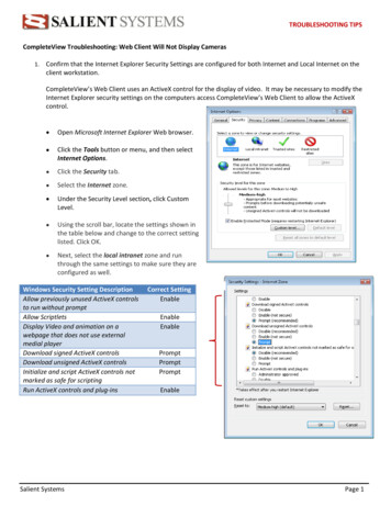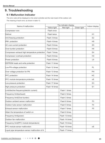
Transcription
X5 Service & Troubleshooting GuideHARDWARE/SOFTWARE09.28.2011
This document is for informational purposes only, and does not constitute a warranty or representation of any kind. Eachcustomer is responsible for selecting what reporting is required by their business and assuring that such reports are accurateand complete. XATA Corporation reserves the right to make changes to this manual and the information contained hereinwithout prior notice to the customer.No part of this document may be reproduced or transmitted in any form or by any means, electronic or mechanical, includingphotocopying and recording, for any purpose without the express written permission of XATA Corporation.In no event will XATA Corporation be liable for direct, indirect, or consequential damages resulting from the use of thisdocument or any defect in the hardware or software described herein, even if it has been advised of the possibility of suchdamages. In some states, the laws do not allow the exclusion or limitation of implied warranties or liabilities for incidental orconsequential damages, so the above limitation or exclusion may not apply.Copyright, XATA Corporation, 2011. All rights reserved.XATA is a registered trademark of XATA Corporation.XATA Corporation965 Prairie Center DriveEden Prairie, MN 55344(952) 894-3680Document Number: XA-6070, Rev. F2 XATA Corporation
Federal Communications Commission RegulationsWarning:Changes or modifications to equipment not expressly approved by the party responsible for compliance could void the user’sauthority to operate this equipment.RF Exposure Warning:When installed as directed, the equipment complies with radiation exposure limits for general population/uncontrolledexposure. To ensure user’s safety and to satisfy RF exposure requirements for mobile transmitting devices, this unit must beinstalled so that a minimum separation distance of 33 cm (13 inches) is always secured between the transmitting structure andthe body of the user or nearby persons.NOTE:This equipment has been tested and found to comply with the limits for Class B digital devices, pursuant to Part 15 – RadioFrequency Devices - of the FCC Rules. These limits are designed to provide reasonable protection against harmful interferencein a residential installation. This equipment generates, uses, and can radiate radio frequency energy and, if not installed andused in accordance with the instructions, may cause harmful interference to radio communications. However, there is noguarantee that interference will not occur in a particular installation. If this equipment does cause harmful interference toradio or television reception, which can be determined by turning the equipment off and on, the user is encouraged to try tocorrect the interference by one or more of the following measures: Reorient or relocate the receiving antenna. Increase the separation between the equipment and receiver. Connect the equipment into an outlet on a circuit different from that to which the receiver is connected. Consult the dealer or an experienced Radio/TV technician for help. XATA Corporation3
Table of ContentsIntroduction . 8X5 Hardware Components . 9Locating the Hardware Part and Serial Numbers .13Maintaining Your X5 Mobile Unit . 14Hardware Locations and Wiring .15Calibration.16Step 1: Prepare for Calibration . 16Step 2: Calibrate a Vehicle . 18Step 3: Calibration Transmission Status. 21Troubleshooting the Mobile Unit . 24Before You Call Support .24Driver Display Troubleshooting & Reboot Processes .24Access Diagnostic Screens & X5 Troubleshooting .26Breakout Box Troubleshooting .27Power Issues Troubleshooting.28X5 Slim Case Lights . 29Interpret Mobile Unit System Messages .30Reboot Messages . 30Communication Messages . 31GPS Messages . 31Other Messages . 324 XATA Corporation
Table of ContentsInterpret Diagnostic Information .33OBD II Troubleshooting .37Hino Converter Troubleshooting .37Hardwired PTO Troubleshooting .38Wiring Configurations and Diagrams . 39Direct Air Switch Wiring Diagram . 39Electric Over Air Diagram – Integrated Indicator Light . 41Electric Over Air Diagram– Separate Indicator Light . 42Air Switch Connections – No Indicator Light . 43Test Message Waiting Light (if installed) .44Replacing Mobile Unit Hardware – RMA Process. 45Removing/Replacing Hardware . 46Replace a Driver Display.46Step 1: Remove the Driver Display . 46Step 2: Replace the Driver Display . 48Remove and Replace a Breakout Box.50Step 1: Remove the Breakout Box . 50Step 2: Replace the Breakout Box . 52Mount the Breakout Box . 54Remove and Replace a Vehicle Power Wiring Harness .55Step 1: Remove the Vehicle Power Wiring Harness . 55Step 2: Replace the Vehicle Power Wiring Harness . 56Replace a Driver Display Cable .59Step 1: Remove a Driver Display Cable . 59Step 2: Replace a Driver Display Cable . 60Replace a Drop Cable .62Step 1: Remove a Drop Cable . 62 XATA Corporation5
Table of ContentsStep 2: Replace the Drop Cable . 64Replace an X5 .67Step 1: Retrieve Vehicle Data from the Existing X5 . 68Step 2: Remove X5 Hardware from Vehicle . 69Step 3: Install the Replacement X5 . 71Step 4: Remove the old X5 from XATANET . 73Step 5: Add the Replacement X5 to XATANET . 75Step 6: Check Vehicle Setup Status. 77Step 7: Complete a Test Trip . 79Step 8: Add the X5 to Exec (for Forms Messaging only) . 80Exec for Windows . 80Remove and Replace the Message Waiting Light .84Step 1: Remove the Message Waiting Light Assembly . 84Step 2: Replace the Message Waiting Light Assembly. 84Remove and Replace the Message Light Harness .86Step 1 Remove the Message Light Harness . 86Step 2: Replace the Message Light Harness . 87Decommissioning a Vehicle .88Redeploy on a New Vehicle .90Troubleshooting Forms Messaging. 91Forms Messaging Data Issues .91Technical Support . 94XATA Solution Support.94General Information .94Escalating an Issue .94Appendix A: Setup on Exec for AS/400 or Exec for Web. 95Create a Unit Profile on Exec for Web . 956 XATA Corporation
Table of ContentsCreate a Unit Profile on Exec for AS/400 . 96Appendix B: Forms Messaging Maintenance Menu . 100Motion Interlock. 101PLN Point Display. 102Discretes Port . 103Vehicle Bus Status . 104Current Position . 105ADV Config . 106AVL Rate. 107Appendix C Test Message Waiting Light . 108Appendix D Micronet CE Wiring Overview . 109X5 Mobile Unit Troubleshooting Form . 110 XATA Corporation7
IntroductionThe XATANET Service & Troubleshooting Guide provides information on the components of the X5XATANET system and how they work together, as well as how to maintain and troubleshoot the system.This guide explains: X5 mobile hardware components, including where they are installed and what they do. Various system messages that may display on the Driver Display and why. Solutions to the most common problems with the X5 mobile unit. How to remove and replace X5 hardware. How to return X5 hardware.If you are unable to solve your issue, technical support information is listed at the back of this manual.The X5 system consists of mobile hardware and software that is connected through cellular or WiFi tothe XATANET web application. Information is sent back and forth between the X5 mobile units and theXATANET web application.The XATANET web application is available through Internet browser on a PC. It is used to view andanalyze data from the X5 mobile units. It also sends routes, messages and other information to theMobile Units. This application also is often called a “Host” because it hosts all the customer data.The XATANET web application also is used to create reports and manage driver, vehicle, and routeinformation.8 XATA Corporation
X5 Hardware ComponentsXATANET Mobile Unit refers to the system installed on a vehicle. Mobile Units collect data entered bythe driver, sent from the engine, and from its own GPS radio, and transmits it to XATANET. It alsoreceives data from XATANET, such as routes, driver logs, and messages.The table below provides an overview of each component of the X5 Mobile Unit.ItemX5 OnboardComputer –Dome(dual mode)X5 OnboardComputer –Slim Case(singlemode)FunctionContains radios,software, and datastorage.Works with satellite,cellular, and Wi-FicommunicationsContains radios,software, and datastorage.Works with cellular andWi-Fi communicationsExternalantennaLocationImageDepends on the vehicle type and ifthere are obstacles to transmission,such as metal farings. The X5 Domemay be mounted to the top, back, orcatwalk. On a straight truck, it maybe mounted on the front of the cargobox towards the top.The X5 Slim Case is mounted insidethe cab and uses a wireless antennamounted externally forcommunications.Usually mounted on top of the cab.(X5 SlimCase only) XATA Corporation9
X5 Service & Troubleshooting GuideItemMountingBracketsFunctionLocationUsed to mount the X5Dome on the vehicle.Under the X5 Dome.Back Mounts areinstalled on the back oftractor, typically on asleeper, extended cab,or when somethinginhibits a roof mount.Generally, on the back of the cab.A roof mount is mostcommon for day cabinstallation.Centered on top of the roof orientedso to allow access to the undersidefrom both sides of the bracket.ImageThe Mounting PlatformBracket is used withRoof Brackets when areefer is directly overthe cab.A catwalk adapter isused with a roof-mountbracket on straighttrucks that include arefrigeration unit and amaintenance catwalk.Mounted as an extension of thecatwalk. This allows the X5 to be outfrom under the reefer unit to obtainthe best signal.X5 Slim Case backmountX5 Slim Case roofmount10 XATA Corporation
Locating the Hardware Part and Serial NumbersItemFunctionLocationBreakoutBoxThis is the interfacebetween the vehicle’spower supply and ECM,and the system.Generally, the Breakout Box isinstalled inside the cab of thetruck. This part should NEVERbe installed in the enginecompartment. The easiest wayto locate this part is to traceeither the drop cable or theDriver Display cable.DriverDisplayThe driver’s computerused to login in/out,record trip status anddelivery information.Shows systemdiagnostic information.Not included at theBasic/Bronze level.It is typically mounted on thedashboard.ImageFor handhelds, the cradle istypically mounted on thedashboard.TREQ -LNOTE: The DriverDisplay software alsocan run on handhelddevices. XATA hascertified select devicesto operate with theXATANET OnboardSystem.TREQ -M4CE-507CE-504Drop CableConnects the X5 to theBreakout Box XATA CorporationDown from the X5, along theback of the cab.11
X5 Service & Troubleshooting GuideItemDisplayCableFunctionConnects the BreakoutBox to the DriverDisplay.LocationImageConnects to the Driver Display,and generally runs through thedash to the Breakout nnects the X5 System Connects to the Breakout Boxto the power supply and and runs to the Deutsch Plug.ECM.EthernetCableOptional: Used toconnect the BreakoutBox to an Ethernetcapable displayConnects to the Breakout Boxand runs to the display.Discrete I/OWiringHarnessOptional: Used toconnect the BreakoutBox to the MessageWaiting LightConnects to the Breakout Boxand runs to the MessageWaiting Light.The MessageWaiting Light onlyapplies to XATANETForms Messagingcustomers.MessageWaitingLightOptional: For XATANETwith Forms Messaging,this lights when amessage is receivedConnects to the i/o DiscretesWiring Harness. In the cab, it ismounted so that the driver willnotice the light.The MessageWaiting Light onlyapplies to XATANETForms Messagingcustomers.12 XATA Corporation
Locating the Hardware Part and Serial NumbersLocating the Hardware Part and Serial NumbersX5 - The part number and serial number are located on a sticker on the side of the X5 near the DropCable connector. The part number is marked with P/N. The serial number is marked with S/N. If thesticker has w
receives data from XATANET, such as routes, driver logs, and messages. The table below provides an overview of each comp