Transcription
TROUBLESHOOTING GUIDEFOREFI SYSTEM CONENTSMAY 2006
TABLE OF CONTENTSEngine Operating System .2Throttle Body .2Control Circuit Operation .3Electronic Control Unit .4Electronic troubleshooting Guida .5EFI Generator Electrical Testing Values .7Component Testing . 8General . 8Relays . 8Stepper Motor . 9Fuel Injector.9Fuel Pressure . 9Map Sensor . 10Oxygen Sensor. l1Magnetic Pick-Up Coil . 12Fuel Pressure Pump . 12Air, Coolant, &Water Temperature Sensors . 13LED Display P.C. Board . 13Battery Charger . 14Exhaust Temperature Switch . 15Coolant Temperature Sendor . 15Oil Pressure Sendor . 15DC Circuit Breaker . 15HighlLow RPM Shutdown . 155Kw and 6,5Kw Wiring Diagram . 168, 10, 12.5 and 14Kw Wiring Diagram . 1720Kw and 25Kw Wiring Diagram . 18 WESTERBEICEEngines & Generators1
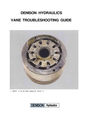
GENERAL DESCRIPTIONENGINE OPERATING SYSTEM DESCRIPTIONThe output driver in the ECU which controls the relays(K , K2) d the control panel indicator lamp(s) is onewhich has Internal current limiting capability of its outputs'and will turn itself off should such an over-currentcondition occur. Therefore, the engine statUs indicatorlamps are of the l2V LED type.The enginelgen.er.ator is equipped with an electronic speedregulated, fuel Injected control system. Engine speed ismaintained constant by varying the amount of air inducedpast a throttle plate into the intake manifold. The throttleplate position is controlled by a rotary proportional actuator energized from a closed loop control circuit whosesignal input is from a magnetic pickup-type speed sensor.The ROM of the MCU contains the program from whichthe engine is controlled. The MCU measures and monitorsthe status of the engine through various inputs and then setsaccordingly the outputs which control the engine. TheMCU has direct control of the amount of the fuel injectedas well as some control of the throttle position. The actualposition of the throttle plate actuator for speed control how ver, is determined by a proportional, integral and derivatIve (PID) analog closed loop control circuit. The MCUmonitors the engine speed and will shut down the engine incase an overspeed condition should ever occur. In addition, theECU has a safety backup overspeed circuit in the unlikelyevent that the MCU fails to respond.This manual provides detailed testing procedures of theoperating system and its components including atroubleshooting chatt and wiring schematics of four EFIgenerators.Fuel is metered to the engine intake manifold by a centralport-type fuel injector system where the amount of fuelinj ted is primarily determined by the engine speed, theengIne load, the engine temperature and the intake airtemperature. Fuel is delivered to the engine by a highpressure fuel pump. The fuel pressure drop across theinj,:"to is maintained onstant by a fuel pressure regnlatorwhich IS ported to the Intake manifold to compensate forpressure variations as a result of engine load changes.Air-fuel management as well as engine operational functionsare performed by an embedded electronic control unit (ECU). nginelgenerator control functions (starting and stopping) areInputted from a remote control panel or from the engineSTARf/OFF switch to the ECU. The ECU then sets therequired operational parameters necessary for the running ofthe engine.THROTTLE BODYThe throttle body, mounted on the intake manifold, is anassembly of the principal components of the EFI(Electronic Fuel Injection System).The EFI is controlled by the ECU (Electronic ControlUnit) which interprets data from sensors that monitor thevital parts of the' engine. The ECU uses this continuousflow of data to determine the appropriate injector pulserate and throttle opening position.A high pressure fuel pump supplies fuel to the area aroundthe injector and the regnlator maintains the fuel pressure inthat area at 35 - 40 PSI.The injector is a solenoid operated pintle valve that metersfuel into the intake manifold depending on engineoperating conditions and generator amperage load asdetermined by the ECU.Air flow into the intake manifold is through the flamearresterlair filter and is controlled by the ECU operation ofthe throttle plate via the actuator (stepper motor). The ottle pla e positioning for proper air flow into the engineIS accomphshed through the ECU interpretation of theengine operating conditions. The Schrader valve is used tomonitor the fuel pressure at the fuel injector and to bleedair after fuel system servicing.On some models an air intake heater is positioned in theintake to heat the incoming air during a cold start.v: WESTERBEKEEngines & Generators2
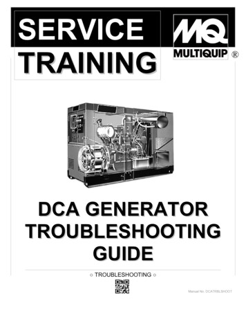
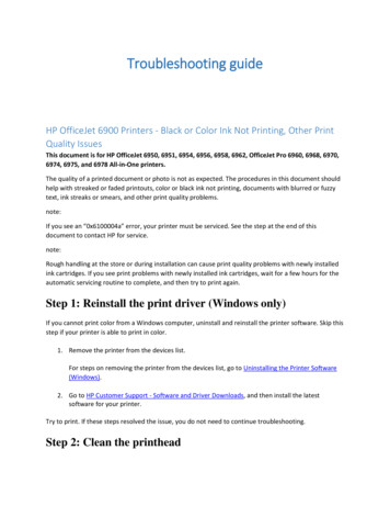
CONTROL CIRCUIT OPERATIONDESCRIPTIONWhen a stop is initiated by momentarily depressing the stopswitch, the ECU will take this command and thende-energize the K2 run relay. This removes DC power to theignition, the fuel pump, and the injector, shutting down theengine. Once the BCU senses zero rpm engine speed (noMPU AC signal) it then releases the latch, which holds thecircuit power on. The green LED light will go out and theECU win revert to an off state.Should a fault occur to initiate an engine shutdown as a resultof low oil pressure, high water injected exhaust elbow.temperature, high engine antifreeze coolant temperature, highengine rpm or low engine rpm, the ECU will ackn wledgethis as a valid stop command. The stop sequence wdl be aspreviously described except that the circuit power willremain on and the fault LED board will register the faultycause by illuminating the related fault LED. This fault LEDwill remain on and will not allow the engine to be restarted.To reset the ECU and tum off the fault LED, the stop switchmust be momentarily depressed. The reset action must beinitiated before the ECU will permit the engine to berestarted.::---.When the engine start/stop switch and the remote start/stopswitch are in their center positions and the green LED is notilInminatOO and the generator is not running, the ECU and allthe engine electrical components are in an off state.When the start switch is actuated (momentarily depressed),the ECU is powered up and a start is assumed. The greenLED will illuminate. The K2 run relay will energize turningon the ignition and the fuel pump. After a time delay ofapproximately 4 seconds, the Kl relay will energize, whichin tum energizes the starter solenoid and an engine crankingsequence will result - starting the engine.Should the engine fail to start within approximately 10-12seconds, the start sequence will be tenninated and the ECUwill go to the off state and the green LED light will go out.When the engine starts, the starter will automaticallydisengage (start relay Kl is de-energized). The green EDlight on the switch is on and circuit power to the ECU ISlatched on. The generator will come up to speed and theengine is now under the control of the ECU.Ql ",,-BREAKERFAULTINDICATOR LIGHTS.START SWITCHSTOPISTARTWITH GREEN u' --""":::'''''''' '-llilFIREBOY, CO DETECTORAND/OR AUXILIARY STOPCONNECTIONofW/WESTERBEKESTART WESTERBEKEEngines & Generators30STOPoREMOTE CONTROLPANEL
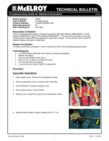
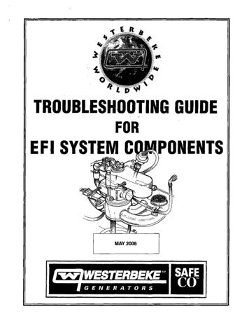
ELECTRONIC CONTROL UNIT (ECU)DESCRIPTIONSetting Engine SpeedThe ECU (Electronic Control Unit) is factory programmedand requires no adjustments by the generator operator. Itcontrols all starting, operating and safety shutdown featureson the engine.The Gain Pot is set at #50 midpoint for optimum systemresponse.Program dipswitches are in the OFF position and should notbe disturbed.The vacant program connector is used by the factory to inputthe operating program into the ECU.The electrical connections from the engine electrical hamessare made to the ECU through two plug connections, one 23pin and one 35 pin and may therefore vary in nU beraccording to the generator model. For further details, consultthe engine circuit wiring diagram in this manual.The ECU is normally set for operation at 60 Hz unlessspecified otherwise, and is internally configured for a 2 poleor 4 pole generator. If it is necessary to replace the E ,make sure it is configured by label for the generator muse.The engine speed can be set for operation at either 50 or60 Hz. Corresponding engine speeds for a 2 pole generatorwould be 3,000 or 3,600 rpm; for a 4 pole generator, 1,500 or1,800 rpm.1. Set up whatever equipment is to be used to measureengine speed or generator output frequency.2. Start up and run the generator at the current operatingspeed and frequency.3. Adjust the GAIN setring between 40 - 60 for best systemreaction to AC amperage load changes.NOTE: A higher GAIN adjustment can induce unstableengine operation. In such cases, lessen the GAINadjustment.ECU ADJUSTMENTSStability TrimENGINE HARNESSWhen changing engine speed, or if an engine huntingcondition should occur, the gain pot may require adjustment.There is no specific set point for this adjustment and it isnormally set to the middle of its range or to a point in .itsrange which obtains optimal engine speed response wlthOUtany tendency of hunting.PROGRAMCONTROLLERDIPSWITCHES - -:-GAINELECTRONIC CONTROL UNIT(ECU)REPLACING THE ECURemove t1ie control box cover. Before attempting to removethe ECU, disconnect its power by removing the fuse fromthe front of the control panel. With the engine hamessconnections unplugged, unscrew the four side screws andremove the ECU from its· holder.INSTALLING THE NEW ECUTo install the new ECU, reverse the above procedure. WESTERBEKEEngInes & Generators4
ELECTRICAL TROUBLESHOOTING GUIDEThe following test procedures wiU require the use ofa multimeter and thewiring diagram (in this manual). Also refer to the relay testingpage. WESrERBEKE recommends that these tests be peiformed by aqualified technician.engine PROBLEMEngine does not crank.TESTING(12 VDC is battery voltage measured to ground)Test lor B (12v) at the clrcuH breaker to the PCboard terminal T4.IIOK.INSPECTION/SOLUTIONCheck lor bad connections at the engine harnessconnector Pt, the red wire, or at the battery onthe starter. Check the connections at the PC boardterminal 4 and althe circuit breaker.Test lor 8 (12v) at the circuH breaker to the panel Look lor a bad connection lrom the circuit breakerfuse end and to the PC board terminal T2.to the luse or at the PC board terminal T2.Replace the circuit breaker.II OK Test lor 8 (12v) lrom the fuse end to the PC boardterminal Tl.IIOK.Test lor 8 (12v) at the relay Kl terminal 30.IIOK.Inspect the connections at the luse or PC boardterminal Tl. Replace the luse.Check lor a bad connection at the engine harnessconnector Pl, pin 3. The redlwhite wire or at Kl,K2, terminal 30.Test lor B (12v) at the starVstop switch terminals Look lor bad connections at the panel connector2 and 10.52, pin 1, whitelblacklred wire to the terminalPC board or at the starVstop switch terminals 21I0K.and 10.Test lor 8 (12v) at the start switch terminal 1Replace the start switch.when the switch is activated.II OK Test lor 8 (12v) at relay Kl, terminal 86.Check lor bad connections at the panel connector52, pin 3, green wire to the PC board. Then checkII OK the engine harness connection at the connectorPl, pin 7-grey wire.Inspect connections on jumpers on the terminalstrip T51 or between any external contactsconnected to T51. Replace the PC board.1I0K.Test lor B (l2v) at relay Kl terminal 85. ActivateInspect lor a bad connection at relay Kl terminal 8the start swHch and alter alew seconds the voltage orange wire or at ECU connector P2, pln2.should drop below .5 volts.Replace the ECUHOK.Actlvate the start swHch, alter 4-5 seconds B (t2v) Look lor a bad connection at relay Kl.should be present at terminal 87 on relay Kl.HOK.Activate the start switch, alter 4-5 seconds check lor Look lor a bad connection at relay Kl, terminal 858 (12v) at the start solenoid.orange wire or at the ECU connector P2 pin.II OK Replace the ECU.Inspect the starter.Check the connections at relay Kt terminal 87.yellow/red wire or at the start solenoid.Replace the starter. WESTERBEKEEngines & Generators5
ELECTRICAL TROUBLESHOOTING GUIDE17Ie following test procedures will require the use of a multimeter and theengine's wiring diagram (in this manual). Also refer to the relay testingpage. WESTERBEKE recommends thai these tests be peiformed by aqualified technician.PROBLEMEngine cranks but fails to start. TESTING(12 VOC is battery voltage measured to ground)INSPECTION/SOLUTIONTest lor B (12v) at terminals 30 and 86on the K2 RelayIIOK.Check lor bad connections at both terminals.Replace the K2 relay.Test lor B (12v) at relay K2, terminal 86 andactivate the start switch. Voltage should be lessthan 5 volts.IIOK.Inspect the connections at relay K2, terminal 86,the green wire, or at the ECU connector P2, pin 19.Replace the ECU.Activate the start switch, test lor B (I2v) atrelay K2, terminal 87.Replace the K2 relay.NOTE: For other possible causes (failure to start) such asfuel pump, speed sensor (MPU),ignition, etc, refer to these sections in this manual.Engine starts, runs but shuts down. Test lor voltage across
60 Hz. Corresponding engine speeds for a 2 pole generator would be 3,000 or 3,600 rpm; for a 4 pole generator, 1,500 or 1,800 rpm. 1. Set up whatever equipment is to be used to measure engine speed or generator output frequency. 2. Start up and run the generator at the current operating speed and frequency. 3. Adjust the GAIN setring between 40 -60 for best system