Transcription
SERVICETRAINING DCA GENERATORTROUBLESHOOTINGGUIDE TROUBLESHOOTING Manual No. DCATRBLSHOOT
CALIFORNIAProposition 65 Warning:Engine exhaust and some of its constituents, and some dust created by powersanding, sawing, grinding, drilling and other construction activities containschemicals known to the State of California to cause cancer, birth defects andother reproductive harm.Some examples of these chemicals are: Lead and lead-based paint.Crystalline silica from bricks.Cement and other masonry products.Arsenic and chromium from chemically treated lumber.Your risk from these exposures varies, depending on how often you do this typeof work. To reduce your exposure to these chemicals: ALWAYS work in a wellventilated area, and work with approved safety equipment, such as dust maskthat are specially designed to filter out microscopic particles.2Multiquip Inc. DCA Generators Troubleshooting Guide Manual No. DCATRBLSHOOT
IMPORTANT!Read the operator's manual for safety instructions before you attempt to troubleshoot. Use extremecaution when troubleshooting power equipment. Never start or run power equipment inside a closedarea, breathing exhaust fumes can kill.Basically, a tool is an object that enables you to take advantage of the laws of physics and mechanicsin such a way that you can seriously injure yourself.This training manual is intended to provide information and procedures to safely troubleshoot and givea basic understanding of troubleshooting techniques for the DCA series generators.You must be familiar with the operations of the DCA series generator before attempting totroubleshoot or make repairs. Basic operating and maintenance procedures are described in theoperation and parts manual supplied with the generator. Use the supplied manual to orderreplacement parts. If you are missing the operation and parts manual, please contact Multiquip Inc toorder a replacement or you may visit our website at www.multiquip.comFor your safety and the safety of others carefully read, understand and observe all instructiondescribed in this manual.Safety precautions should be followed at all times when servicingequipment. Consult operations manual for more safety information.THIS GUIDE IS USED FOR TRAINING PURPOSE ONLY AND NOT FOR GENERAL DISTRIBUTIONMultiquip Inc. DCA Generators Troubleshooting Guide Manual No. DCATRBLSHOOT3
SAFETYPLEASE REMEMBER SAFETY FIRST!!!!!!!!!!!!!This troubleshooting guide emphasizes safety precautions necessary during operation and testing.Safety precautions should be followed at all times when operating, maintaining and testing powerequipment. Failure to read and understand safety precautions and warnings could result in injury toyourself and others.PLEASE READ ALL SAFETY PRECAUSIONS AND WARNINGS LISTED IN THE SECTIONMARKED SAFETY BEFORE OPERATING, SERVICNG OR TESTING THIS EQUIPMENT.If you are not sure of the instructions or procedures, seek qualified help before continuing.This manual is not intended to be a substitute for properly trained personnel. Repairs should only beattempted by qualified, trained technicians. Each installation, application and operations of generatorscan create its own set of circumstances. No manual can cover every possible situation. When indoubt, ask. There is no such thing as dumb questions. BE SAFE!!!!!!!The following tests should only be carried out by qualified and/or experienced technician who havereceived SAFETY TRAINING ON LIVE EQUIPMENT.All test instruments and their leads / connectors / probes must be checked to ensure that they aresuitable for the voltage levels being tested, and are in good working order.Whenever the generator is running, always assume and proceed as if voltage is present at thegenerator leads and at the regulator panel connections. Caution must be observed. Otherwise, seriouspersonal injury or death can result.Before any work is done, and testing is conducted appropriate measure should be taken to preventunexpected start-up of the generator.ALWAYS DISABLE ENGINE BEFORE WORKING INSIDE A GENERATOR TOPREVENT ACCIDENTIAL STARTUP!Proper grounding is necessary to help prevent shock if the frame becomes energized during livetesting.Residual voltage is present at the generator leads, selector switch, circuit breaker, gages andat the regulator panel connections, even with the regulator disconnected or fuse removed.Caution must be observed or serious personal injury or death can result. Consult qualifiedpersonnel with any questions.Always wear proper PPE when conducting live voltage tests4Multiquip Inc. DCA Generators Troubleshooting Guide Manual No. DCATRBLSHOOT
CONTENTS Troubleshooting Charts . .6o No Voltage – Residual Voltage Only . .7o No Voltage . .8o Low Voltage – No Load . . .9o Low Voltage – On Load . . .10o High Voltage . . . .11o Voltage Unstable – No Load . . .12o Voltage Unbalance . . . .13TROUBLESHOOTING PROCEDURES Testing Exciter Field Resistance .14Testing Voltage Input to AVR – Open Delta Windings .15Manual Excitation Test – Using a Battery & Voltage Balance Test . .16Rotating Rectifier Test . .17Testing Rotating Rectifier Using a 12V DC Test Light . .18Exciter Field Insulation Test . .19Stator Insulation Test .20Test Stator Windings . .21Test Main Rotor Field .22Test Exciter Armature .23DATA CHARTS Table of Generator Data . .24Automatic Voltage Regulator . . .25Gen-Set Data . . . .26WYE Diagrams . . . . .27Voltage Selector Switch Automatic Voltage Regulator . .28-29GENERATOR GLOSSARY Index . . .30Multiquip Inc. DCA Generators Troubleshooting Guide Manual No. DCATRBLSHOOT5
TROUBLESHOOTING CHARTSThis manual is intended to suggest a systematic approach to locating and correcting generatormalfunctions. The steps have been arranged in an attempt to do the easy checks first and prevent furtherdamage when troubleshooting a disabled machine.The first step of troubleshooting is to gather as much information as is possible from operating personneland individuals present during the failure. Typical information includes: How long the unit had been operating;What voltage was the generator running at when the fault occurred;What loads were on line;Information about the application the generator was operating is sometimes crucial to determinefault and cause of fault;Prior issues with machine;Maintenance history;Weather conditions;Protective equipment that did or did not function;In addition, information as to the operating condition of the generator's prime mover is vital. Has the prime mover been maintaining constant speed? If not, have there been extended periods ofunder speed operation?Has the prime mover experienced an over-speed condition? If yes, what was the maximum speed,and how long did the unit operate at that elevated speed?The generator speed should be maintained at rated nameplate value during all operating tests. Thefrequency of the generator depends upon rotational speed.Always make a thorough visual inspection to check for obvious problems before attempting to run thegenerator. Remove covers and look for any obvious problems. Burnt windings, broken connectors, burntwires, mounting brackets, etc., can usually be identified through inspection. Look for any loose or frayedinsulation, loose or dirty connections and broken wires. Check for any foreign objects, loose nuts, bolts andelectrical connections.If possible rotate the generator rotor by hand to be sure it turns freely.If serious problems can be identified before attempting to operate the machine, additional damage can beavoided.6Multiquip Inc. DCA Generators Troubleshooting Guide Manual No. DCATRBLSHOOT
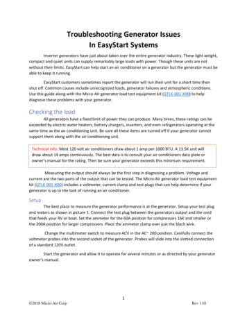
NO VOLTAGE – RESIDUAL VOLTAGE ONLYMultiquip Inc. DCA Generators Troubleshooting Guide Manual No. DCATRBLSHOOT7
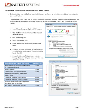
NO VOLTAGE8Multiquip Inc. DCA Generators Troubleshooting Guide Manual No. DCATRBLSHOOT
LOW VOLTAGE – NO LOADMultiquip Inc. DCA Generators Troubleshooting Guide Manual No. DCATRBLSHOOT9
LOW VOLTAGE – ON LOAD10Multiquip Inc. DCA Generators Troubleshooting Guide Manual No. DCATRBLSHOOT
HIGH VOLTAGEMultiquip Inc. DCA Generators Troubleshooting Guide Manual No. DCATRBLSHOOT11
VOLTAGE UNSTABLE – NO LOAD12Multiquip Inc. DCA Generators Troubleshooting Guide Manual No. DCATRBLSHOOT
VOLTAGE UNBALANCEMultiquip Inc. DCA Generators Troubleshooting Guide Manual No. DCATRBLSHOOT13
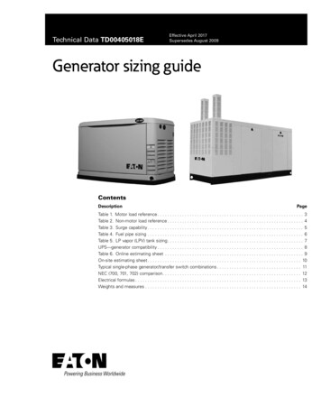
TESTING EXCITER FIELD RESISTANCE14Multiquip Inc. DCA Generators Troubleshooting Guide Manual No. DCATRBLSHOOT
TESTING VOLTAGE INPUT TO AVROPEN DELTA WINDINGSMultiquip Inc. DCA Generators Troubleshooting Guide Manual No. DCATRBLSHOOT15
MANUAL EXCITATION TESTUSING A BATTERY & VOLTAGE BALANCE TEST16Multiquip Inc. DCA Generators Troubleshooting Guide Manual No. DCATRBLSHOOT
ROTATING RECTIFIER TESTMultiquip Inc. DCA Generators Troubleshooting Guide Manual No. DCATRBLSHOOT17
TESTING ROTATING RECTIFIERUSING A 12V DC TEST LIGHT18Multiquip Inc. DCA Generators Troubleshooting Guide Manual No. DCATRBLSHOOT
EXCITER FIELD INSULATION TESTMultiquip Inc. DCA Generators Troubleshooting Guide Manual No. DCATRBLSHOOT19
STATOR INSULATION TEST20Multiquip Inc. DCA Generators Troubleshooting Guide Manual No. DCATRBLSHOOT
TEST STATOR WINDINGSMultiquip Inc. DCA Generators Troubleshooting Guide Manual No. DCATRBLSHOOT21
TEST MAIN ROTOR FIELD22Multiquip Inc. DCA Generators Troubleshooting Guide Manual No. DCATRBLSHOOT
TEST EXCITER ARMATUREMultiquip Inc. DCA Generators Troubleshooting Guide Manual No. DCATRBLSHOOT23
TABLE OF GENERATOR DATA24Multiquip Inc. DCA Generators Troubleshooting Guide Manual No. DCATRBLSHOOT
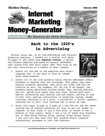
AUTOMATIC VOLTAGE REGULATORThere are four connectors that attach to the AVR and two wires to the AVR terminals. The AVR also has threepotentiometers, only one is for course adjustment the other two should NOT be touched.IMORTANT: There is no procedure for directly testing the AVR, use process of elimination.8 amp fuse MQ part # 6978K753Open delta leads and excitation leads connect tothe AVR on this connector.DCA 25 ONLYA Wire is – YELLOWB Wire is – ORANGEC Wire is – WHITED Wire is – GRAYJ Wire is – REDK Wire is – BLUEDCA 45 to DCA 150A Wire is labeled AB Wire is labeled BC Wire is labeled CD Wire is labeled DJ Wire is labeled JK Wire is labeled K(wires colors are black)This connector has no outside connection and has acouple of bridge jumper wires.P1, P2 Wire is WHITE and are bridged together.ℓ, K Wire is WHITE and are bridged together.Wires connected here are for AVR internal sensing.Two WHITE wires from the V-LegRelay are connected here.U Wire is RED and is connected to terminal # 14 on the voltage selector switch.V Wire is WHITE and is connected to V-Leg Relay (RY1)W Wire is BLUE and is connected to terminal # 36 on the voltage selector switch.This potentiometer (pot) is thevoltage course adjustment pot.This connects the Rheostat (VR) to the AVR.1 Wire is GRAY3 Wire is YELLOWVISUAL REMINDER: The potsare positioned similar to abackwards capital letter ‘L’DO NOT! adjust the other two pots, these are factory pre-set.Multiquip Inc. DCA Generators Troubleshooting Guide Manual No. DCATRBLSHOOT25
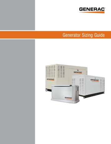
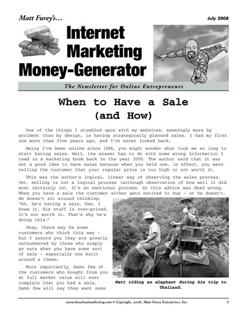
GEN-SET DATAThe chart below can be used as a reference guide for measuring resistance on the Gen-SetCROSS REFERENCE CHARTRESISTANCE MEASURED IN OHMS ΩMain ArmatureGeneratorGen-SetModel #Model #DCA-25SSAIAVR InputsMainExciterArmatureFieldArmatureFieldAC OutputsDC DC-UVWJ K-0.1420.4751-A-BField SSIU / SSIU2DF-02700.12440.317.6-0.92.7DCA-25USI / CA-45SSIU2 / CA-60SSI / SSI2DB-06610.0481.80.2115-0.611.83DCA-70SSJU / SSJU2DB-08310.0321.20.0817.3-0.371.11DCA-70SSI / 07500.0461.790.13718.8-0.671.85DCA-70USJ / 500.0461.790.13718.8-0.671.85DCA-85SSJU / SSJU2DB-10010.0211.330.0817.3-0.320.96DCA-85USJ /USJ2DB-10010.0211.330.0817.3-0.320.96DCA-85SSK / 51.520.0817.3-0.280.84DCA-125SSM / -13810.0151.520.0817.3-0.280.84DCA-125USJ / USIDB-13810.0151.520.0817.3-0.280.84DCA-150SSK / 16510.0111.750.0817.3-0.270.82DCA-150SSJU / -16510.0111.750.0817.3-0.270.82DCA-150USJ / USJ2DB-16510.0111.750.0817.3-0.270.82Name of PartWiresLocation of WiresMeasuring between AC Output leadsExciter FieldJ&K(connected to AVR)Exciter ArmatureUVW(connected to rotating rectifier)Main FieldDC DC –(connected to rotating rectifier)Main Armature12 Load Leads4 Open Delta Leads(AC Outputs)(connected to AVR – A,B,C,D)26U1 to X1U2 to X2V1 to Y1V2 to Y2W1 to Z1W2 to Z2Multiquip Inc. DCA Generators
The generator speed should be maintained at rated nameplate value during all operating tests. The frequency of the generator depends upon rotational speed. Always make a thorough visual inspection to check for obvious problems before attempting to run the generator. Remove covers and look for any obvious problems. Burnt windings, broken connectors, burnt