Transcription
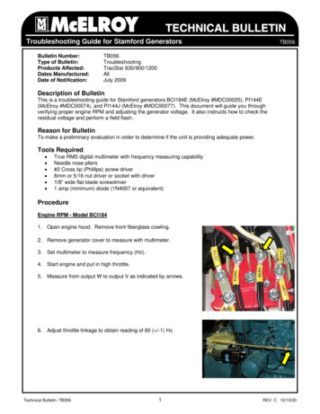
Troubleshooting Guide for Stamford GeneratorsBulletin Number:Type of Bulletin:Products Affected:Dates Manufactured:Date of Notification:TB056TB056TroubleshootingTracStar 630/900/1200AllJuly 2009Description of BulletinThis is a troubleshooting guide for Stamford generators BCI184E (McElroy #MDC00025), PI144E(McElroy #MDC00074), and PI144J (McElroy #MDC00077). This document will guide you throughverifying proper engine RPM and adjusting the generator voltage. It also instructs how to check theresidual voltage and perform a field flash.Reason for BulletinTo make a preliminary evaluation in order to determine if the unit is providing adequate power.Tools Required True RMS digital multimeter with frequency measuring capabilityNeedle nose pliers#2 Cross tip (Phillips) screw driver8mm or 5/16 nut driver or socket with driver1/8” wide flat blade screwdriver1 amp (minimum) diode (1N4007 or equivalent)ProcedureEngine RPM - Model BCI1841. Open engine hood. Remove front fiberglass cowling.2. Remove generator cover to measure with multimeter.3. Set multimeter to measure frequency (Hz).4. Start engine and put in high throttle.5. Measure from output W to output V as indicated by arrows.6. Adjust throttle linkage to obtain reading of 60 ( /-1) Hz.Technical Bulletin: TB0561REV. C 12/10/20
Troubleshooting Guide for Stamford GeneratorsTB056Engine RPM - Model PI1441. Start engine and set to high throttle.2. View engine RPM displayed on console.3. Verify engine speed is 1800 ( /-25) RPM.4. If the RPM is out of spec, call McElroy Tech Support.Output Voltage - Model BCI1841. Open engine hood. Remove front fiberglass cowling.2. Unplug heater cable.3. Remove generator top cover to access terminals and outboardside cover to access Automatic Voltage Regulator (AVR).4. Start engine and put in high throttle.5. Measure phase-to phase voltages at generator terminals:Measure from W to V, then from W to U, then from V to U. Eachphase should read 240( /-5) volts.NOTE: If voltage is very low or zero, shut off engineand go to “Check Residual Voltage.”6. Locate voltage potentiometer at bottom left side of AVR. Adjustpotentiometer until meter reads 240( /-5) volts.7. Shut off engine and reinstall covers.8. Re-connect the heater power cable.Output Voltage - Model PI1441. Remove front fiberglass cowling.2. Remove generator outboard side cover to access AutomaticVoltage Regulator (AVR).3. Start engine and set to high throttle. Turn heater off.4. Make sure GFCI is not tripped.5. View displayed voltage on front panel meter. Reading should be240( /-5) volts AC.Technical Bulletin: TB0562REV. C 12/10/20
Troubleshooting Guide for Stamford GeneratorsTB0566. Locate voltage potentiometer at top left of AVR. Adjustpotentiometer until meter reads 240( /-5) volts.7. Shut off engine and reinstall covers.Residual Voltage CheckPerform this test if voltage is very low (or zero) and fuses aregood/GFCI is not tripped.871. With engine OFF, remove covers from top and outboard sidefrom generator.2. Inspect all connections. Make sure crimps are good andgenerator terminals are tight.3. Inspect wires for worn places of signs of shorting againstgenerator enclosure. Repair any damage.4. Disconnect wires F1 & F2 from Automatic Voltage Regulator(AVR). Secure wires to insure terminals cannot touch anything.F1F2BCI184E5. Start the engine and set to high speed.6. Measure AC volts from terminal 7 to terminal 8. Reading shouldbe at least 5 volts. If not, proceed to Field Flashing.PI144Field Flashing1. Reconnect leads F1 & F2 to their respective terminals.E2. Connect a wire from negative battery terminal to F2.WARNING! Do not use TracStar’s battery for field flashing.Battery cannot be connected to chassis ground.3. Connect a wire from cathode of diode (end with stripe) to F1.4. Connect a wire from positive battery terminal to anode of diode(end without stripe).WARNING! A diode must be used to prevent AVR damage.5. Start engine and measure voltage from terminal 7 to terminal 8.It should be between 170 and 250 volts.6. Turn off engine.7. Remove wires and diode. Re-install all covers.Technical Bulletin: TB0563REV. C 12/10/20
Troubleshooting Guide for Stamford GeneratorsTB056DownloadsFor more in-depth troubleshooting, go to www.stamford-avk.com and download these twomanuals. Follow the instructions within to determine and repair the generator fault.Replacement AVR Part Numbers:McElroy #MDC00060McElroy #MDC00061AVR for BCI184AVR for PI144If no problem is found and the generator is still not producing adequate power, check themachines In-Service date on the McElroy website (www.mcelroy.com). If it is less than one yearfrom that date, contact McElroy Manufacturing for possible warranty evaluation. If it is after thatperiod, contact Cummins Generator Technologies (Newage) at 1-800-367-2764 for furthertroubleshooting.Technical Bulletin: TB0564REV. C 12/10/20
TECHNICAL BULLETIN REVISION HISTORY LISTINGPART NO:TB056DESCRIPTION: TROUBLESHOOTING GUIDE FOR STAMFORD 19/25/15BYRLTRLT12/10/20 BEADESCRIPTION OF REVISIONON SHEET 3, NOTE #6 CORRECTED ’50 TO 61 HERTZ’ TO ’59 TO 61 HERTZ’.REVISED TO CHANGE THE WARRANTY MENTIONED IN THE DOCUMENTFROM TWO YEARS TO ONE YEAR.RE-WRITTEN TO INCLUDE GENERATORS FOR T630/T900 SERIES 1,T630/T900 SERIES 2, AND T1200.
Troubleshooting Guide for Stamford Generators TB056 Engine RPM - Model PI144 1. Start engine and set to high throttle. 2. View engine RPM displayed on console. 3. Verify engine speed is 1800 ( /-25) RPM. 4. If the RPM is out of spec, call McElroy Tech Support. Output Voltage - Model BCI184 1. Open engine hood. Remove front fiberglass cowling. 2. Unplug heater cable.