Transcription
844G/854G GigaCenter InstallationGuideDecember 2014#220-00759, Rev. 11
ContentsAbout This Guide. 5Chapter 1: Overview . 7Introduction. 8Agency Listing . 11Pre-Installation Options . 13Wall Mount Installation Options . 13Additional Installation Options . 16Site Preparation . 18Wi-Fi Considerations . 19Before You Begin . 19Installation Tips . 20Required Tools and Supplies . 20Chapter 2: Connectorized Installation . 23Unpacking the GigaCenter. 23Installation Variables . 24Tabletop Mounting the GigaCenter . 25Tabletop Mounting Dimensions . 26Installing the Composite Cable - Tabletop Mount . 27Proprietary Information: Not for use or disclosure except by written agreement with Calix. Calix. All Rights Reserved.
4Wall Mounting the GigaCenter . 30Wall Mounting Dimensions . 30Wall Mounting the Fiber Management Tray . 32Installing the Composite Cable - Wall Mount . 33Installing the GigaCenter onto the Fiber Management Tray . 34Chapter 3: UPS Installation . 37Mounting the Universal Power Supply . 37Installing the Power/Signal Cable . 40Chapter 4: Final Set-up and Testing . 43Connecting Outside Services . 43Wi-Fi Protected Set-up (WPS) LED Behavior . 45LED Behavior . 46LED States and Status . 48Appendix A. 51Cleaning Fiber Connectors . 51Proprietary Information: Not for use or disclosure except by written agreement with Calix. Calix. All Rights Reserved.
5About This GuideThis document provides general installation practices for the Calix 844G or 854G GigaCenter.This document also provides a general description of the products, and guidance for planning,site preparation, power installation, splicing to the outside plant, and basic troubleshooting.Intended AudiencesThis document is intended for use by network planning engineers, outside plant engineers, fieldsupport personnel, and craft personnel responsible for installation and maintenance of Calixpremises equipment.Federal Communications Commission (FCC) StatementThis equipment has been tested and found to comply with the limits for a Class A digital device,pursuant to Part 15 of the FCC rules. These limits are designed to provide reasonable protectionagainst harmful interference when the equipment is operated in a commercial environment. Thisequipment generates, uses, and can radiate radio frequency energy, and, if not installed and usedin accordance with the instruction manual, may cause interference to radio communications.Operation of this equipment in a residential area may cause harmful interference; the user willbe required to correct the interference at his expense.Safety NoticesThis document uses the following safety notice conventions.DANGER! Danger indicates the presence of a hazard that will cause severepersonal injury or death if not avoided.WARNING! Warning indicates the presence of a hazard that can cause severepersonal injury if not avoided.CAUTION! Caution indicates the presence of a hazard that can cause minor tomoderate personal injury if not avoided.ALERT! Alert indicates the presence of a hazard that can cause damage toequipment or software, loss of data, or service interruption if not avoided.DANGER! CLASS 1 LASER PRODUCT. INVISIBLE LASER RADIATIONMAY BE PRESENT. Fiber optic radiation can cause severe eye damage orblindness. Do not look into the open end of an optical fiber.Proprietary Information: Not for use or disclosure except by written agreement with Calix. Calix. All Rights Reserved.
6IMPORTANT SAFETY INSTRUCTIONSWhen using your telephone equipment, basic safety precautions must always be followed toreduce the risk of fire, electric shock, and injury to persons, including the following: Do not use this product near water. For example, near a bathtub, washbowl, kitchen sink, orlaundry tub, in a wet basement, or near a swimming pool.Avoid using a telephone (other than a cordless phone) during an electrical storm. There maybe a remote risk of electric shock from lightning.Do not use the telephone to report a gas leak in the vicinity of the leak.Use only the power cord and batteries indicated in this manual. Do not dispose of batteriesin a fire as they may explode.Check with local code for possible special disposal instructions for batteries.For external power supplies, the external power supply used in this device is to be Class IIor a Limited Power Source (LPS) power supply.Proprietary Information: Not for use or disclosure except by written agreement with Calix. Calix. All Rights Reserved.
Chapter 1OverviewThe Calix 844G or 854G GigaCenter terminates passive optical network (PON) fiber at thesubscriber's premises and provides industry standard interfaces for the subscriber'sinformation, communication, and entertainment equipment. From single family residentialunits or multi-dwelling units, to small business applications, Calix GigaCenters enablesubscriber to receive broadband data, voice over Internet protocol (VoIP) telephone service,digital RF video, and Internet protocol television (IPTV) over a single fiber.The Calix 844G and 854G GigaCenters are next generation residential premises servicedelivery platforms that extend the access network into the home and act as a strategiclocation for control of the gigabit experience. Supporting broadband connectivity within thehome and managing subscriber voice, data and video services, this intelligent, highperformance service platform integrates a 2.5 GPON optical interface with switching androuting functions that manage premises network traffic at speeds up to 1 Gbps. TheGigaCenter service interfaces include: carrier class wireless networking with 802.11ac Wi-Fiand four Gigabit Ethernet (GE) ports for IPTV video and data services, two integrated voicelines supporting carrier grade VoIP and network-based TDM voice circuits, a USB port forhome networking services, and an option for RF video.Note: For additional information on achieving carrier class wireless networking, refer to RGWi-Fi Best Practices Guide available on the Calix Resource Center.Proprietary Information: Not for use or disclosure except by written agreement with Calix. Calix. All Rights Reserved.
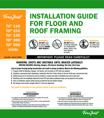
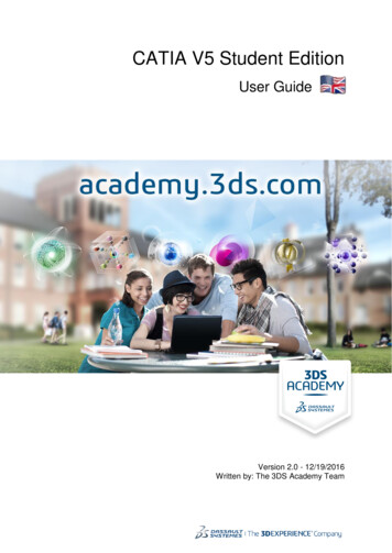
8854G-1 GigaCenterIntroductionThis document describes the installation of the following: 844G-1 GigaCenter, 2 POTS, 4 Gigabit Ethernet ports, Dual Wi-Fi, 1 USB, UPS PowerInterface844G-2 GigaCenter, 2 POTS, 4 Gigabit Ethernet ports, Dual Wi-Fi, 1 USB, 12 VDCPower Interface with On/Off switch854G-1 GigaCenter, 2 POTS, 4 Gigabit Ethernet ports, Dual Wi-Fi, 1 USB, 1 RF Video,UPS Power Interface854G-2 GigaCenter, 2 POTS, 4 Gigabit Ethernet ports, Dual Wi-Fi, 1 USB, 1 RF Video,12 VDC Power Interface with On/Off switchThere are three types of installation configurations:1. Vertical Table-top Configuration - A base stand is attached to the GigaCenter and placedon any available flat surface. Incoming and outgoing connections are plug-and-play.2. Wall Mount Configuration - This enclosure-less configuration mounts the GigaCenter toany available vertical surface using the mounting slots molded into the provided splicetray. Incoming and outgoing connections are plug-and-play.Proprietary Information: Not for use or disclosure except by written agreement with Calix. Calix. All Rights Reserved.
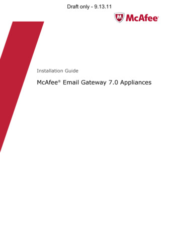
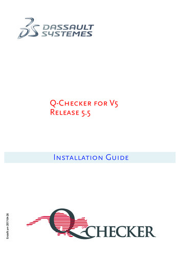
93. Structured Wiring Enclosure (SWE) Configuration - Similar to the wall mountconfiguration, the SWE Configuration mounts the unit to a SWE Enclosure using thewall mount slots molded into the splice tray. Incoming and outgoing connections remainplug-and-play.Note: In configuration #1 above, it is assumed that the incoming fiber connection hasbeen spliced into a Network Interface Device (NID) or a Local Convergence Point(LCP) enclosure and terminated with an SC/APC fiber pigtail for attachment to theGigaCenter.Note: In configuration #2 and #3 above, it is assumed that the incoming fiber drop hasbeen routed near the wall mount for SWE mount location and can be routed into thesplice tray as appropriate.Powering OptionsThe 844G and 854G GigaCenter is available in any of two different powering options: Attached to any 110 or 220 VAC power outlet using the supplied 12 VDC walltransformer.Attached to an indoor grounded or ungrounded Universal Power Supply (UPS)providing life-line service in the event of a power failure. The UPS is connected to localpower using the provided molded power cord.Note: Power cord configurations must be appropriate for use in the country where theGigaCenter is being deployed.Note: Only Calix provided and approved power cords or voltage adapters should beused to connect the 854G/855G GigaCenter.Mounting Options700GE or 800GE devices can be mounted in a variety of different environments: Vertical Wall MountHorizontal Wall MountVertical Tabletop MountStructured Wiring Enclosure (SWE) - Not ShownProprietary Information: Not for use or disclosure except by written agreement with Calix. Calix. All Rights Reserved.
10Wall Mount VerticalWall Mount HorizontalTable Top MountSplice Tray and Base Stand (included)Note: Do not mount the GigaCenter flat on a tabletop or ceiling.Proprietary Information: Not for use or disclosure except by written agreement with Calix. Calix. All Rights Reserved.
11Agency ListingFCC WARNING: These devices comply with Part 15 of the FCC Rules and Regulations.Operation is subject to the following conditions:This device may not cause harmful interference, and, this device must withstand anyinterference received, including interference that may cause undesired operation.The ONT has been tested and found to comply with the limits for a Class B digital devicepursuant to Part 15 of the FCC Rules and Regulations. These limits are designed to providereasonable protection against harmful interference when this equipment is operated in acommercial environment. This equipment generates, uses, and can radiate radio frequencyenergy and, if not installed and used in accordance with the instructions in this guide, maycause harmful interference to radio and television communications.Hazardous materialsThe externally mounted power supply includes a battery for back-up purposes. This battery isclassified as hazardous material and should be disposed of according to the manufacturer'srecommendations.Applicable standardsFollowing is a list of standards that apply to GigaCenter products:GigaCenter StandardsTelcordia GR-303Telcordia GR-909Telcordia GR-63Telcordia GR-950Telcordia GR-1089Telcordia GR-49Telcordia GR-2890Telcordia GR-499Telcordia GR-1244ITU G983.1TR-TSY-000077TR-TSY-000083TA-NWT-000406ANSI T1.231ANSI T1.403ANSI T1.410IETF RFC 2495IETF RFC 1757IETF RFC 2131IETF RFC 951IETF RFC 1514FSAN (Issue 3)UL 1950UL 1697FCC Part 15NEC (National Electrical Code)REA (Rural Electric Association)Canadian ICES-003IEC-61000 4-5 SurgeEN55022 Class AETSI 300-386EN 60950-1EN 60825-1ACMA A-TickACMA C-TickEuropean ConformityProprietary Information: Not for use or disclosure except by written agreement with Calix. Calix. All Rights Reserved.
12Product labelingThe following required labeling shows the laser class and IEC standard that defines the laserused in this product.Laser specifications Complies with 21 CFR 1040.10 and 1040.11 except for deviations pursuant to LaserNotice No. 50, dated June 24, 2007.Nominal laser wavelength: 1310 nmLaser Radiation Maximum Output: 3.2 mWPulse Duration: 6.45 x 10⁻¹¹ s to 6.45 x 10⁻¹⁰ sLaser standards GigaCenter: Class 1 Laser product.1310nm or 1490nm Laser Transmitter: Class 1 Laser product with a Class 3a internalhazard.Radiated emissions This Class-B digital device complies with radiated emissions requirements as defined inCanadian ICES-003.Power cable The unit must be powered by an external power source as follows: CE marked (EU),FCC (US), UL listed power source marked Class II, Limited Power Source (LPS) andrated output between 10-15 VDC (12 VDC nominal), 2.5 Amp minimum.Note: Calix recommends a 7 wire, #16 AWG (2 wires @ 16AWG, 5 wires @ 24AWG), ULapproved cable be used between the unit and the UPS at a drop length not to exceed 70 feet(21.3 meters).Note: Calix connectorized (2 x 4) 8-pin to 7-pin power cables are recommended for use withthe unit. This cord configuration is available in 4 foot (1.2 meters) and 10 foot (3 meters)lengths. For deployments where greater than 10 feet (3 meters) is required, a 25 foot (7.6meters) cable is available that can be cut to length (9-pin connectorized on ONT end and noconnector on UPS end).Proprietary Information: Not for use or disclosure except by written agreement with Calix. Calix. All Rights Reserved.
13Pre-Installation OptionsWhen planning for fiber attachment to the GigaCenter, two options are most oftenconsidered: The incoming fiber connection has been spliced into a Local Convergence Point (LCP)or similar demarcation point and fitted with an SC/APC fiber pigtail for attachment tothe unit.A 5mm drop fiber has been routed to the wall mounted splice tray and fusion spliced toan SC/APC fiber pigtail for attachment to the unit.Determine the optimal spot to locate the GigaCenter for Wi-Fi best performance.Note: For additional information on optimizing Wi-Fi reception, refer to RG Wi-Fi BestPractices Guide available on the Calix Resource Center.You can pre-install a 844-1/854-1 GigaCenter at the customer premises prior to turning upservices. Pre-installation includes the following steps: Physically mounting the unit to a wall or Structured Wiring Enclosure inside thecustomer's home.Installing and securing a composite or drop cable (includes the fiber optic cable).Splicing or connecting the composite cable to a Fiber Management Tray (splice tray)located behind the wall-mounted unit.Once the pre-installation is complete, cap the end of the fiber pigtail to avoid any potentialdanger from laser emissions. When ready, the unit and the optional Uninterruptible PowerSupply (UPS) are installed inside the customer premises.Note: This document includes installation instructions for the UPS in addition toinstructions for installing the unit itself.Wall Mount Installation OptionsWhen mounting the GigaCenter onto a wall or inside a Structured Wiring Enclosure, the unitcan be installed with or without a UPS.Note: All hardware mounting is designed such that cable lengths are minimized andcables/cords can be routed as directly as possible.Note: For all configurations, power cord lengths of 3 foot (1 meters), 10 foot (3 meters), and20 foot (6 meters) are available.Proprietary Information: Not for use or disclosure except by written agreement with Calix. Calix. All Rights Reserved.
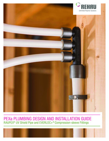
14Mounting OptionsRefer to the following page for illustrations of the various mounting options. Vertical Wall Mount Option A - The 844G/854G is mounted to any rigid surface withthe UPS installed within 4 to 10 feet (1.2 to 3 meters). Power for the UPS is provided viaan appropriate 2 or 3-prong 110/220 VAC receptacle. The (2 x 4) 8-pin (ONT/RSGend) to 7-pin terminal block connector (UPS end) cable provides 12 VDC power andsignaling to the GigaCenter. The fiber pigtail is either routed out the left-hand side andconnected to a LCP or NID or is stored in the splice tray directly behind the GigaCenter.Subscriber services exit the unit out the the left hand side. Horizontal Wall Mount Option B - Similar to Option A, the unit is mounted such thatservices exit the unit out the bottom and the UPS is mounted directly below. Thisconfiguration also may be appropriate for deployments inside a SWE.Note: The power and signal cable is terminated only at the GigaCenter end (2 x 4) 8-pinconnector while the connection at the UPS is manually wired (screw-down) to the 7-pinterminal block connector provided with the UPS. Since the power/signal cable is 25 feet(7.6 meters) in length, the two devices need not be in close proximity to one another.Horizontal Wall Mount Option C - This deployment option does not include back-uppower. The Calix provided 110/200 VAC to 12 VDC power converter is plugged directlyinto the wall socket or power receptacle. The fiber pigtail and subscriber services exit theunit out the bottom of the unit. This option is also suitable for use in SWEenvironments.Vertical Wall Mount Option D - Identical to Option C except the GigaCenter isrotated 90 counter-clockwise with fiber and subscriber services exiting the unit out theleft-hand side. This option is also suitable for use in SWE environments. Vertical Wall Mount Option AProprietary Information: Not for use or disclosure except by written agreement with Calix. Calix. All Rights Reserved.
15Horizontal Wall Mount Option BHorizontal Wall Mount Option CProprietary Information: Not for use or disclosure except by written agreement with Calix. Calix. All Rights Reserved.
16Vertical Wall Mount Option DAdditional Installation OptionsThe following components may be required to complete your installation:UPSA tabletop UPS is available from Calix. This UPS is available in a variety of powerconfigurations. The tabletop UPS includes a power/signal cord that runs from theGigaCenter to the UPS.Proprietary Information: Not for use or disclosure except by written agreement with Calix. Calix. All Rights Reserved.
17UPS Power CordPower cords are available for North America (NA), European Union (EU), United Kingdom(UK), Australia/New Zealand (AU/NZ), and Brazil (BR).Signal Cable4 foot (1 meter) and 10 foot (3 meters) cables are available, terminated at both ends. A 20foot (6 meters) cable is also available (terminated at the GigaCenter end with the other endcapable of being "cut to l
844G/854G GigaCenter Instal