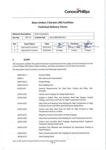
Transcription
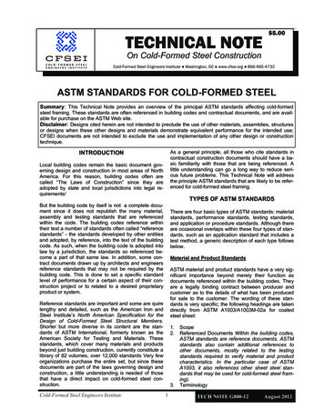
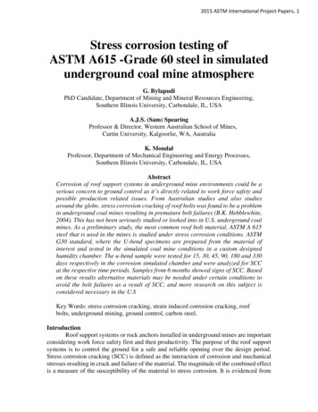
ASTM A711Steel Forging StockASTM A788Steel Forgings, General RequirementsASTM A961Common Requirements for Steel Flanges, Forged Fittings, Valves,and Parts for Piping ApplicationsASTM E18Standard Test Methods for Rockwell Hardness of Metallic MaterialsASTM E165Liquid Penetrant Examination for General IndustryASTM E1444Standard Practice for Magnetic Particle InspectionAPI 6FBSpecification for Fire Test for End ConnectionsNACE MR 0175Sulfide Stress Cracking Resistant Metallic Materials for Oil FieldEquipmentEN 10204Metallic products – types of inspection documentsALL/CMP/SPE/003TDT 03: Coated Alloy Steel BoltingALL/CMP/SPE/002TDT 02: Austenitic Stainless Steel and Superduplex BoltingALL/SUP/LOG/PRO/2000 Export Packing and Marking Logistics ProcedureDOC/ENG/SPE/0010Project Coating SpecificationH8-GEN-00-020-S010100Bayu Undan Piping Material Specification2PRE-REQUISITION REQUIREMENTS2.1GENERALThe proposal to supply hub connectors shall include, but not be limited to the following: Proof of extensive successful service application under comparable conditions with thechoice of similar size, rating and materials. Documentation to demonstrate compliance with 304.7.2 of ASME B31.3 current edition. Type testing details as witnessed and certified by independent quality certifyingorganisations or similar. Leak test procedure for the hub connector joints. Details of production tests or scheme for sampling and testing. Equivalent or superior material specifications for components including informationabout relevant material properties, and material specifications for product forms usedfor manufacturing. The documentation provided shall demonstrate the following:oThe design provides for joints that are leakage proof within the bursting pressureof pipe (of size and thickness as per the Piping Class) butt welded to the hub.oPressure/Temperature rating for the hub connector is at least equal to ASMEB16.5 for the same pressure class and material quality.oAt rated design pressure, the hub connector is leak-free while being subject tobending moments due to pipe loading. The quantified bending moment (in kNm)Bayu Undan and Darwin LNG FacilitiesTechnical Delivery terms for the Supply of Hub Connectors2 of 11
oodue to piping load that can be safely withstood by the hub connector (under fulldesign pressure / temperature conditions) shall be listed for each size andpressure rating (covered under the relevant Piping Class in H8-GEN-00-020-S010100).Fatigue loading shall not cause any leakage in the bolted connection before a leakor failure will occur in adjoining welds or pipes, i.e. bolts or seals shall not besubjected to critical fatigue stress values at any cyclic load combination ofpressure and bending as described above.The design complies with the fire test requirements of API Specification 6FB, partsI and II.Note:1. Leakage of hub connector joint shall be zero (no pressure drop/decay and visible leak) whilehydrostatic tested under 1.5 times the design rated pressure.2. Fugitive emissions from the flange joint shall effectively be zero. The supplier shall provideinformation to describe testing procedure and predicted leakage rate.2.1BOLT-UP REQUIREMENTS / ASSEMBLY PROCEDUREFor each applicable Piping Class furnish tables covering:3 Clamp, Hub, Seal Ring, Bolt size and length, and weight of each unit. Complete bolting up procedures including the following minimum information shall beprovided along with the bid:oRequirements for alignment inclusive of tolerances (facial and lateral both)oHandling of sealsoDescription of toolsoBolt tensioning instructionsoBolt tensioning valuesoGuidelines for qualifying the personnel to carry out bolt up and assemblyMATERIALSMaterial for all components shall be supplied in accordance with the ASTM specifications identifiedin this document. Supplemental and modified requirements to the identified ASTM materialspecifications are outlined under each item as necessary.Repair by welding is not permitted.Component material specifications required for Bayu Undan piping classes are summarised inTable 1.Bayu Undan and Darwin LNG FacilitiesTechnical Delivery terms for the Supply of Hub Connectors3 of 11
TABLE 1 – HUB CONNECTOR MATERIAL SPECIFICATIONSPiping Class3MaterialTypeRatedTemperatureRange (0C)Size RangemmHub incl.BlindClampSeal RingBoltNutDC1, DC2, DC2N,EC1, EC2, FC1, FC1NCS & LTCS-29 to 150DN25 to DN300A105NAISI 4140 1, 5AISI 4140 2, 5A193 B7 8A194 2HDD1N, ED1N, FD1NDuplex S31803-50 to 150DN25 to DN300A182 F51A320 L7M 1 ,6A182 F55 S32760SOLUTION ANNEALEDA320 L7 8A194-4A194-7AISI 4140 2, 5A320 L7 8A194-4A194-7316SS 2A193 B8M CL2 8A194 8M2, 7DL1, FL1LTCS-46 to 150DN25 to DN300A350 LF2 Class 1DS1, DS1N, ES1, FS1316SS-100 to 150DN25 to DN300A182 F3164AISI 4140316SS1, 5Notes:1.2.3.4.5.6.7.8.AISI 4140 and A320 L7M (MODIFIED) Clamps shall be supplied coated with Zinc Nickel, 10-12micron (corrosion resistance performance equivalent 1500hrs against SaltSpray Fog Test as per ASTM B117-16.Components exposed to the process shall comply with NACE MR0175 requirements.Refer to respective Piping Class sheet for pressure / temperature ratings. Hub connector size range for all classes is DN20 to DN250, except that for ANSI Class 2500 sizerange up to DN300 is allowed. Usage other than as specified shall be approved by COP Technical Authority.A182 F316 Hubs, maximum carbon content 0.035% (equivalent to 316L). All other properties shall meet ASTM A182-F316 requirements.AISI 4140 Clamps and Seal Rings, all sizes, to be Charpy Impact Tested at ‐46 C, 41J average, 30J single minimum as per Galperti recommendation.A320 L7M (MODIFIED) Clamps, all sizes, to be Charpy Impact Tested at ‐73 C, 27J average, 20J single minimum as per A320 Specification.A182 F55 S32760 Seal Rings, all sizes, to be Charpy Impact Tested at -50 C, 50J average, 40J single minimum as per Galperti recommendation.Bolting materials shall be as identified in the relevant Piping Class and in full compliance with requirements specified in ALL/CMP/SPE/002 or 003 as applicable to the type ofmaterial.Bayu Undan and Darwin LNG FacilitiesTechnical Delivery terms for the Supply of Hub Connectors4 of 11
3.1 HUBHub Material shall be as specified for the piping class and as summarised in Table 1.Maximum thickness under tolerance shall be 0.3mmBevel ends shall be in accordance with ASME B16.253.1.1ASTM A105ASTM A105 forgings shall be supplied in the normalised condition. Supplementary requirement S2regarding heat treatment and marking shall apply.For carbon steel material, carbon content shall not be more than 0.23% and carbon equivalent (CE)shall be 0.43% weight as determined by the formula:CE C Mn/6 (Cr Mo V)/5 (Ni Cu)/15Note, this is more restrictive than S4 of A105 which specifies 0.47% for sections 2” thick or less, and0.48% for sections above 2” thickness.3.1.2ASTM A350-LF2Supplementary requirement S55 of ASTM A961regarding MPI of the finished forging shall apply to10% of the items with size DN50 and above. The acceptance criteria shall be in accordance withASME VIII Div 1, Appendix 6.Flanges shall be normalized. Hubs shall be quenched and tempered.Impact test results shall be at least 27 Joules (for standard specimen 10 x 10 mm) as an average ofthree tests. One result may be lower than 27 Joules, but shall have a minimum of 21 Joules. For subsize specimens, the impact values required by ASTM A350 shall be multiplied by 1.5.3.1.3ASTM A182-F316Molybdenum content of the material shall not be less than 2.5% by weight.All austenitic stainless steels shall be supplied and used in solution heat-treated condition.Items shall be supplied in white pickled condition except for machined surfacesAustenitic Stainless Steel used for hubs shall be dual stamped, i.e. carbon content of 316L andmechanical properties of 316.3.1.4ASTM A182-F51Pitting resistance number (PREN) for the material shall be not less than 33 when calculated using theformula: PREN %Cr 3.3*%Mo 16*%NNitrogen content shall be 0.15% minimum.For hubs, ferrite in the final heat treated condition shall be between 40 – 60%.Charpy V-notch Impact testing shall be carried out at -500C.For a standard specimen, the average impact value of three specimens shall be 40J or more, with anallowable single value of 31J. For sub-size specimen, impact value less than 70% of the standardspecimen is not acceptable.Bayu Undan and Darwin LNG FacilitiesTechnical Delivery terms for the Supply of Hub Connectors5 of 11
Hardness shall be measured and shall be less than 28 HRC.Repair welding is not permitted.Items shall be supplied in white pickled condition.3.2CLAMPThe clamp shall be manufactured by forging. Cast construction is not acceptable.The forging shall be manufactured in accordance with ASTM A788 including supplementaryrequirements S5, S13, S18 and S19.Charpy Impact Testing to be carried out as follows: AISI 4140 Clamps, all sizes, to be Charpy Impact Tested at ‐46 C, 41J average,30J single minimum. A320 L7M (MODIFIED) Clamps, all sizes, to be Charpy Impact Tested at ‐73 C, 27Javerage, 20J single minimum.The billet used to produce alloy steel clamp forgings shall be produced in accordance with ASTMA788 with grade 4140 chemical composition in accordance with ASTM A29.3.3SEAL RINGSeal rings shall be machined from forged material of composition and grade specified for the pipingclass. All seal rings shall comply with NACE MR0175.Charpy Impact Testing to be carried out as follows:3.4 AISI 4140 Seal Rings, all sizes, to be Charpy Impact Tested at ‐46 C, 41J average, 30Jsingle minimum. A182 F55 S32760 Seal Rings, all sizes, to be Charpy Impact Tested at -50 C, 50J average,40J single minimum.BOLTS AND NUTSBolting materials shall be as identified in the relevant Piping Class and in full compliance withrequirements specified in ALL/CMP/SPE/002 or 003 as applicable to the type of material.4APPLICABILITY OF NACE MR0175 REQUIREMENTSFor piping classes designated for sour service, the hub forging and seal ring shall be supplied in acondition that meets NACE MR0175 requirements for the material.Additionally, for carbon steel, sulphur content shall be restricted to 0.010% by weight.Material certificates/compliance statements shall clearly indicate the required property and NACEcompliance requirement and the compliance details against each of those specified details.Bayu Undan and Darwin LNG FacilitiesTechnical Delivery terms for the Supply of Hub Connectors6 of 11
5NON-DESTRUCTIVE EXAMINATIONNDE methods and acceptance criteria, extent and sampling shall be in accordance with the ASTMSpecification material design code and as specified herein.5.1Inspection StandardsItemType of InspectionsApplicable StandardsForging (hub,clamp, seal ring)VisualASME B31.3, 344.2Magnetic Particle Test (MT)ASTM A275, ASTM E1444 andASME V Article 7ASTM E165 and ASME VArticle 6ASME B31.3, 344.6 and ASMEV Article 5ASTM A370Dye Penetrant Test (PT)Ultrasonic Test (UT)Hardness Test (HT)Impact TestASME B31.3, 323.3 and ASTMA370Refer:ALL/CMP/SPE/002 (TDT 02)Austenitic Stainless Steel andSuper Duplex BoltingALL/CMP/SPE /003 (TDT 03)Coated Alloy Steel BoltingBolts/nutsDye-Penetrant Test (PT) shall be carried out on the bevel ends plus a 25mm band adjacent to thebevel (both inside and outside surface) for 10% of the hubs.Magnetic Particle Test (MT) may be applied instead of PT, if it is not feasible to carry out PT or whenthe work efficiency and detection rate of defects is better.5.1ACCEPTANCE CRITERIA5.2.1Visual ExaminationVisual examination shall be carried out in accordance with ASME V Article 9.Forgings shall be free from defects such as Cracks, Mechanical Marks, Abrasions, Pits, Scale, Fins etcOther item shall be free from defects and to a standard acceptable to the principal’s inspector.5.2.2Magnetic ParticleThe techniques specified in ASTM A275 and ASTM E1444 shall be used to determine the presence ofany longitudinal and transverse flaws, using fluorescent particles. All flaws or indication of flaws shallbe ground out to their full extent and the resultant wall thickness and diameter of the surface defectfree component shall comply with the product specification.Bayu Undan and Darwin LNG FacilitiesTechnical Delivery terms for the Supply of Hub Connectors7 of 11
5.2.3Dye Penetrant TestsThe techniques specified in ASTM E165 shall be used to determine the presence of any longitudinaland transverse flaws. All flaws or indication of flaws shall be ground out to their full extent and theresultant wall thickness and diameter of the surface defect-free component shall comply with theproduct specification.Linear indications longer than 1.6mm are not acceptable.Bayu Undan and Darwin LNG FacilitiesTechnical Delivery terms for the Supply of Hub Connectors8 of 11
6TRACEABILITY AND CERTIFICATION REQUIREMENTSAll materials shall be supplied with EN 10204 3.1 certificates for each batch/heat traceable to theactual items/components being supplied. Certification for bolting shall comply with TDT 02 and TDT03.Certification for forged components and other product forms shall comply with the requirements ofASTM A788.Both specified and actual mechanical properties and chemical compositions, inclusive of NACEMR0175 requirements (if applicable), shall be included in type II certificates.Positive material identification test results for materials other than carbon steel shall be included intype II certificate.All the documents relating to quality assurance and quality control including certificates shall be inEnglish and readily legible. Documents provided in other languages or illegible shall not be acceptedand shall be referred to COP before clearing final inspection.7MARKING REQUIREMENTSThe items shall be low stress (round nose) stamped at the locations as follows:Hub Connectors: On the outer rimClamps: On the outside surface along the centre lineSeal Rings: On the outer rim or on the label attached to the gasket.Details of marking for hub connectors shall be in line wi
ASTM A711 Steel Forging Stock ASTM A788 Steel Forgings, General Requirements ASTM A961 Common Requirements for Steel Flanges, Forged Fittings, Valves, and Parts for Piping Applications ASTM E18 Standard Test Methods for Rockwell Hardness of Metallic Materials ASTM E165 Liquid Penetrant Examination for General Industry ASTM E1444 Standard Practice for Magnetic Particle
