Transcription
RESOURCE GUIDEMATERIALS AND SERVICESJULY 2019 JUNE 2020
JUNE 14-16, 2020llllExpert-led educationExpansive trade showValuable networking withpeers worldwideAffordable, flexible registrationoptions to fit your budgetEASA 1331 Baur Blvd. St. Louis, MO 63132 USAPhone: 1 314 993 2220 Fax: 1 314 993 1269Email: easainfo@easa.com Website: www.easa.com
Table Of ContentsIdentification MaterialsEASA Lapel Pin. 1EASA Logo Uniform Patch. 1EASA Logo Vinyl Decals. 1Promotional/Customer Education MaterialsElectrical Engineering Pocket Handbook. 2Failures in Three-Phase Stator Windings. 2Getting the Most from Your Electric Motors. 2Guide for the Repair of Power and Distribution Transformers (EASA AR200). 3Mechanical Reference Handbook. 3Recommended Practice for the Repair of Rotating Electrical Apparatus(ANSI/EASA AR100-2015). 3The Effect of Repair/Rewinding on Motor Efficiency EASA/AEMTRewind Study and Good Practice Guide to Maintain Motor Efficiency. 4Guidelines for EASA Imprinted Products. 4Engineering Reference/Education Materials And ToolsAC Motor Redesign. 5AC Motor Verification and Redesign (with integrated AC & DC motorwinding database) – Version 4. 5Chart – Bolts and Nuts. 5Chart – Commutator Machining. 6Chart – Cylindrical Roller Bearing. 6Chart – High-Potential Tests Using AC / High-Potential Tests Using DC. 6Chart – Lock Nuts and Lock Washers for Ball Bearings. 6Chart – Motor Lead Wire. 7Chart – Radial Ball Bearing. 7Chart – Round Magnet Wire Data. 7Fundamentals of DC Operation and Repair Tips. 7Fundamentals of Pump Repair. 8Internal Connection Diagrams. 8Mechanical Repair Fundamentals of Electric Motors, 2nd Edition. 8Motor Rewind Data – Version 4. 8Principles of Medium and Large AC Motors. 9Root Cause Failure Analysis. 9Technical Manual. 9(Continued on next page)i
Table Of ContentsNameplatesEASA Nameplates. 10Engineering FormsAC Stator Form Coil Data Sheet. 10Stator Core Test Forms. 10Warranty Report Form. 10Winding Data Forms.11Technical Training & Easa Seminars/Webinars How To Wind Three-Phase Stators (Self-Paced, Interactive Training for Stators600 Volts or Less) – Version 2. 12Vibration Analysis for Service Centers. 12EASA Vo-Tech. 12Management And Sales Training Advanced Inside Sales. 13Employee Safety Guide. 13Job Descriptions for EASA Service Centers. 13New Directions in Inside Sales (DVD). 14The Perfect Sales Call. 14NewsletterCurrents. 15Price ListsPrice lists. 16-21Order FormOrder form. 22ii
IDENTIFICATION MATERIALSEASA Lapel PinAnnounce your affiliation with EASA in a fashionable manner with this professionallooking lapel pin. This handsome copper-plated lapel pin is the perfect match for ourindustry and will look perfect on a sport coat, dress shirt or tie.EASA Logo Uniform PatchAdd the mark of professionalism to uniforms, shirts, jackets, coveralls and otherapparel. The 4” by 1 ½”, high-quality embroidered emblem looks great when worn asa shoulder patch or on the chest. Sold in sets of 10.EASA Logo Vinyl DecalsAvailable in two sizes, these vinyl decals look great on any smooth surface. The large(8 ½” x 3 ⅛”) decal will set off items like metal cabinets, doors, lockers and servicecenter walls. The handy small (5” x 1 ⅞”) decal is just right for smaller applicationssuch as toolboxes, notebooks, folders, car bumpers and rear windows. Sold in setsof 10.EASA Resources – How To Order1
PROMOTIONAL/CUSTOMER EDUCATION MATERIALSElectrical Engineering Pocket HandbookFilled with practical information, the handbook makes a great “give-away” itemfor your customers and potential customers. When imprinted with your companyinformation, it reminds customers to call on your firm when in need of electricalapparatus sales or service. Use the handbook to make everyone in your organizationa sales person. If one of your technicians helps a customer with a troubleshootingproblem, for example, remind the customer of this valuable assistance by providingEASA’s professionally produced handbook with your company’s contact information.Imprint Your Logoand ContactInformation HereActual size: 3.5” x 6”Failures in Three-Phase Stator WindingsFailures in Three-Phase Stator Windings is a six-page brochure on heavy, enameledstock that assists members in a variety of ways such as a training aid, an informative handout or a promotional mailer. For the greatest impact and a lastingimpression, include your company imprint on the front cover, inside or both. Thebrochure features large, full-color photographs of the most common failures in threephase stator windings, and brief descriptions of the possible causes. A photographof a good stator is included for the purpose of comparison. The booklet also isavailable in French and Spanish.Imprint Your Logoand ContactInformation HereAvailablein FrenchandSpanish!Actual size: 8.5” x 11”Getting the Most from Your Electric MotorsGetting the Most from Your Electric Motors helps end-users obtain the longest, mostefficient and cost-effective operation from general and definite purpose motors.The booklet covers items such as: Installation, startup and baseline information Operational monitoring and maintenance How to read a motor nameplate Motor storageUse it as a great marketing tool. Provide a copy to customers with your contactinformation and branding imprinted on the cover.Imprint Your Logoand ContactInformation HereThis publication is available for FREE download at www.easa.com.Actual size: 8.5” x 11”2Promote Your Business with EASA Handbooks
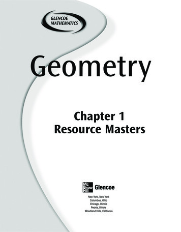
PROMOTIONAL/CUSTOMER EDUCATION MATERIALSGuide for the Repair of Power and DistributionTransformers (EASA AR200)EASA AR200GUIDEL APPAICARTRVIOSEREA SAICNUSATELECF O R T H E R E PA I R O F P O W E R A N DDISTRIBUTION TRANSFORMERSTE AIASSOCReliable SolutionsTodayEASA’s Guide for the Repair of Power and Distribution Transformers (EASA AR200)establishes guidelines for each step of the repair of power transformers. It describesrecord keeping, tests, analysis and general guidelines for the repair of powertransformers. Transformers covered are liquid-filled distribution or transformers upto 10 MVA and 69 kV, and dry type distribution and power transformers up to 5 MVAand 25 kV. Some of the topics addressed include condition assessment, failure investigation, insulation tests, rewinding of both dry and liquid-filled units and assessingsuitability for service. Entire sections are devoted to winding considerations, repair ofdry type transformers and repair of liquid-filled transformers.An appendix addresses electrical testing safety considerations.Actual size: 8.5” x 11”This publication is available for FREE download at www.easa.com.Imprint Your Logoand ContactInformation HereMechanical Reference HandbookThis handbook contains carefully selected materials designed to assist repair firms intheir everyday work. Just as important, your customers and potential customerscan use this 90-page pocket handbook as a handy reference for mechanical data formotors and driven equipment. When imprinted with your firm’s contact information,the Mechanical Reference Handbook also makes a great tool for sales calls and otherpromotional activities.Recommended Practice for theRepair of Rotating Electrical Apparatus(ANSI/EASA AR100-2015)Actual size: 3.5” x 6”Recognized as anAmerican NationalStandard (ANSI)ANSI/EASAA R 1 0 0 - 2 0 15EASA Standard AR100-2015RECOMMENDEDPRACTICEFOR THE REPAIR OF ROTATINGELECTRICAL APPARATUSActual size: 8.5” x 11”With the American National Standards Institute (ANSI) status noted on the cover,EASA’s Recommended Practice for the Repair of Rotating Electrical Apparatus (ANSI/EASA AR100-2015) is an important publication to distribute both internally and tocustomers. Order extra copies so you and everyone at your repair facility will have thiscomprehensive set of guidelines nearby for handy reference. EASA’s RecommendedPractice promotes integrity and good faith among members, suppliers and customersby maintaining a level of workmanship that will produce quality products. Adherence to EASA’s Recommended Practice helps member firms improve the quality of theiroperations while providing their customers with guidelines for judging whether repairshave been performed in an acceptable manner.This publication is available for FREE download at www.easa.com.Use EASA Promotional Materials to Grow Your Business3
PROMOTIONAL/CUSTOMER EDUCATION MATERIALSThe Effect of Repair/Rewinding on Motor EfficiencyEASA/AEMT Rewind Study and Good Practice Guideto Maintain Motor EfficiencyGet extra copies of this important publication for your technicians and customers.It explains the findings of the study conducted by EASA and the Association ofElectrical and Mechanical Trades (AEMT) that analyzed the impact of repair andrewinding on the energy efficiency of electric motors. In addition to its conclusionthat using best repair/rewind practices does not degrade efficiency, the study alsoshows that motors can be rewound/repaired multiple times with no loss in efficiency.Also, the Good Practice Guide outlines good practice repair methods used to achievethe results. It can be used as a stand-alone document and contains repair tips, relevantmotor technology and information about sources of losses in induction motors thataffect efficiency.Actual size: 8.5” x 11”This publication is available for FREE download at www.easa.com.Guidelines for EASA Imprinted Products*PricingPricing for imprinted products is based on the quantity purchased as well as the number of colors (inks) used. There is anadditional charge for a requested proof whether or not an order is placed. An additional 2 invoicing fee will be charged ifnot paid in full in advance.The prices for imprinted products listed in the Price List at the back of this brochure are for black ink only. Imprinted priceslisted are an estimate only. Contact Customer Service Representative Nancy Kemper at EASA Headquarters ( 1 314 993 2220or nkemper@easa.com) for exact prices on ALL orders for imprinted products.Colors (Inks)When submitting any artwork, you MUST specify the Pantone PMS color codes for all inks (other than black). If you do notknow these codes, ask your logo designer, graphic artist or marketing department/firm for the details. You may also refer towww.pantone-colours.com for help in determining the codes. EASA is not responsible for any incorrect colors based onincorrect color codes submitted.Acceptable Artwork Formats Submit one file containing the logo/graphic/text EXACTLY as it should appear on the imprinted product. The logo/graphic/text must fit within the printable area (2.75” wide x 2.25” tall). The preferred format for submission is Adobe Illustrator .AI (native Illustrator file) or Adobe Illustrator .EPS(Encapsulated PostScript). Vector files, such as those created by Adobe Illustrator, are resolution independentand create the sharpest images no matter what the size. If your .AI/.EPS/vector graphic artwork submission contains fonts, the graphics should be converted tooutlines to ensure fonts display correctly. Although it is not preferable, logos may be submitted as high-resolution (600 dpi or higher) JPGs or TIFs.Logos taken directly from your company website are generally low resolution (72 or 96 dpi) and ARE NOTsuitable for printing. Artwork also may be submitted in a Portable Document Format (PDF) if the original image will fit within theprintable area (2.75” wide x 2.25” tall) and is to be printed as one solid color.Booklet ReprintsIf your imprint order is EXACTLY the same as a previous order, submit a copy of the cover from the previous order. Pleasealso indicate all Pantone PMS colors.* Products available for imprints are: Electrical Engineering Pocket Handbook; Mechanical Reference Handbook; Getting the Most from YourElectric Motors; and Failures in Three Phase Windings.4EASA’s Recommended Practice Has ANSI Status
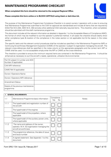
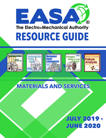
ENGINEERING REFERENCE MATERIALS AND TOOLSAC Motor RedesignAC MotorRedesignAvailableinSpanishEASA’s AC Motor Redesign manual explains how to make all possible changes inthe ratings of AC electric motors, within design limitations. Besides mathematicalformulas, it provides guidelines on the limitations for each type of redesign. Theseare useful in determining whether a desired new rating is possible before the motor isstripped. Terms are expressed in both English and metric units. Each chapter containsat least one example to guide you through your own redesigns. The publication also isavailable in Spanish.This publication is available for FREE download at www.easa.com.Electrical Apparatus Service Association, Inc.1331 Baur Boulevard St. Louis, Missouri 63132314-993-2220 Fax: 314-993-1269 www.easa.comActual size: 8.5” x 11”AC Motor Verification and Redesign (with integratedAC & DC motor winding database) – Version 4Version 4 of EASA’s AC Motor Verification & Redesign program on CD-ROM hasbeen combined with EASA’s Motor Rewind Data – Version 4 program to form a singleapplication that addresses service center winding needs. The marriage of these twosoftware programs will provide seamless access to a full array of motor windingreference and redesign functions. Among its many features, the new verificationprogram and redesign software provides new usability features such as fraction andbasic math format for entering core dimensions, and more flexibility for redesignoptions. The integration with the EASA motor rewind database allows users to directlyreference those database records to validate their original winding data, or for bare coreredesigns. The Version 4 program is an indispensable tool for verifying winding dataand accurately calculating redesign options. The new flexibility in comparing redesignoptions allows service centers to design windings that best meet their customers’ needs. BOLTS AND NUTSCOMMON BOLT GRADE MARKINGSASTM AND SAE GRADE MARKINGS FOR STEEL BOLTS AND SCREWS*GRADE MARKINGNo markSPECIFICATIONMATERIALCOMMENTSSAE—Grade 1Low or medium carbon steel.ASTM—A 307Low carbon steel.SAE—Grade 2Low or medium carbon steel.SAE—Grade 5Medium carbon steel, quenchedand tempered.SAE Grade 5.0; yield strength is 90,000 to120,000 psi (6,300 to 8,400 kg/cm2), dependingupon bolt diameter.ASTM—A 449If no grade markings appear, SAE Grades 1 or2 are presumed, with yield strength as low as60,000 psi (4,200 kg/cm2), depending upon boltdiameter.SAE—Grade 5.2Low carbon martensite steel,quenched and tempered.SAE Grade 5.2; the same strength as Grade5.0 but has a lower temperature rating; maycarry the “A 325” designation.A 325ASTM—A 325Type 1Medium carbon steel, quenchedand tempered. Radial dashesoptional.When “A 325” appears in the center of thehead, with or without radial dashes, the bolt isASTM A 325 Type 1, a variety commonly usedin structures.ASTM—A 325Type 2Low carbon martensite steel,quenched and tempered.None.A 325A 325ASTM—A 325Type 3Atmospheric corrosion(weathering) steel, quenched andtempered.BCASTM—A 354Grade BCAlloy steel, quenched andtempered.SAE—Grade 7Medium carbon alloy steel,quenched and tempered. Rollthreaded after heat treatment.None.SAE—Grade 8Medium carbon alloy steel,quenched and tempered.ASTM—A 354Grade BDAlloy steel, quenched andtempered.SAE—Grade 8.2Low carbon martensite steel,quenched and tempered.SAE Grade 8.0, with a yield strength of 150,000psi (10,500 kg/cm2).SAE Grade 8.2; the same as Grade 8.0 but hasa lower temperature limit.ASTM—A 490Type 1Alloy steel, quenched andtempered.None.A 490A 490ASTM—A 490Type 3Atmospheric corrosion(weathering) steel, quenched andtempered.Chart – Bolts and NutsEASA’s laminated Bolts and Nuts Chart provides a bounty of useful information.One side of the chart shows the most commonly used bolt grade markings. Thereverse side shows bolt tightening torque values for both metal-to-metal contactand non-metallic parts bolted to metalic parts. The chart also lists precautions fortightening bolted joints.* ANSI/ASME B18.2.1-2012.Besides these grade markings, various codes or logos are used by manufacturers to identify themselves.ELECTRICAL APPARATUS SERVICE ASSOCIATION, INC.1331 Baur Blvd. St. Louis, MO 63132 U.S.A. 314-993-2220 Fax 314-993-1269 www.easa.com easainfo@easa.comCopyright EASA 2015–0915RC3CActual size of all charts: 8.5” x 11”Keep Employees Up-To-Date with EASA Reference Materials5
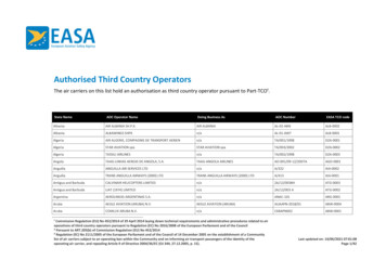
ENGINEERING REFERENCE MATERIALS AND TOOLSChart – Commutator Machining COMMUTATOR MACHININGEASA’s laminated Commutator Machining Chart includes valuable informationfor the service center. The troubleshooting guide includes a table as a guide toassess the condition of the commutator and to aid in solving and eliminatingthe cause. The other side contains information on turning and undercuttingthe commutator.TURNING AND UNDERCUTTINGPREPARING THE ARMATURE1 Check tightness of commutator bolts (tightening nut)while commutator is hot. Tighten to manufacturer’sspecifications.3 Make sure bearing seats run true before machining thecommutator.2 Repair commutator and armature winding as needed.4 Wrap armature winding to keep chips out while machiningthe commutator.TURNING THE COMMUTATORSURFACE SPEEDSingle-point carbide toolft/min 0.26 x D x rpm where D(commutator diameter) is in inchesm/min 0.00314 x D x rpm where D(commutator diameter) is in mm300-500 ft/minSynthetic diamond tool90-150 m/minMax 750 ft/min*DEPTH OF CUTFEED RATE230 m/min*0.007 – 0.010 in0.18 – 0.25 mm0.005 – 0.007 in/rev0.13 – 0.18 mm/rev*Or follow recommendations of manufacturer.Note: Use a flat file to chamfer the ends of the commutator bars (0.040 in/1 mm).COMMUTATOR RUNOUT AND FINISH 5000 ft/minPeripheral speed 5000 ft/minMaximum total indicated runout0.0030” (0.076 mm)0.0015” (0.038 mm)Maximum total indicated runout in any quadrant0.0015” (0.038 mm)0.0010” (0.025 mm)Maximum between adjacent bars0.0002” (0.005 mm)0.0002” (0.005 mm)Maximum taper (in/ft)0.0020”/ft (0.051 mm/m)Surface finish40 to 60 micro-inches (1.02 to 1.52 microns)CopperUNDERCUTTING THE COMMUTATORChart – Cylindrical Roller BearingEASA’s Cylindrical Roller Bearing Chart provides useful information in a handyand durable format. One side of the chart shows the maximum and minimumshaft diameters and end bell housing bores (in inches) for roller bearings mostfrequently used in electrical rotating equipment. The reverse side of the chartincludes nominal bearing dimensions in inches and millimeters. The ABMAnumbers listed are for single-row, cylindrical roller bearings. It, too, is covered bya high-quality lamination that protects it from stains, spills and smudges.1 Type ofundercutU-shaped and beveled, as shown in Figure 1. (Note: In certaincases, the shop manager may determine that a different typeof undercut should be used.)2 Depth ofundercutFactory specifications vary. A good rule to follow: make thedepth equal to 1 - 1 ½ times the slot width.3 Cleaningof slotsUse slotting files and hand scrapers to eliminate mica finsalong the sides of slots.Figure 1Bevel Bevel the bar edges 0.015” (0.4 mm).MicaMicaClean the slots using clean, oil-free air.CopperCopperU-shaped undercuts and bevels.CYLINDRICAL ROLLER BEARING DIMENSIONS4 Polishing ish the commutator with a fine-grit stone or sandpaper to eliminate any minor burrs. The surface finishshould200beSeriesno more than 40 to 60 micro-inches (1.02 to 1.52 microns).300 SeriesODemery paper. ElectricallyWidth conductiveABMABore in the surface of theODcommutatorWidthNote: Never useparticles can lodgeMicaBearingbars and cause smminchesGrowler and0.393730 43622.4409170.6693St. Louis, MO1663132 U.S.A. 314-993-2220 www.easa.com1.1811 1331 Baur62 Blvd. 2.44090.629930RU03 Fax 314-993-1269301.181172 easainfo@easa.com2.8346190.7480Copyright EASA2016 – L APPARATUS SERVICE ASSOCIATION, INC. Adapted from ABMA Std. 20, Table 1, Part 3.CAUTIONHigh-PotentialTests TESTSUsing ACHIGH-POTENTIALUSING ACELECTRICAL APPARATUS SERVICE ASSOCIATION, INC.1331 Baur Blvd. St. Louis, MO 63132 U.S.A. 314-993-2220 Fax 314-993-1269 www.easa.com easainfo@easa.comCopyright EASA 2015 – 1115RC3CBe sure to follow all applicable safety procedures associated with high-potential testing before, during and following the test.INSULATION CONDITION TESTScylndr brng chrt 115.indd 1Chart – High-Potential Tests Using ACHigh-Potential Tests Using DCEASA’s high quality, laminated cards for service center use, High-Potential TestsUsing AC and High-Potential Tests Using DC, provide extensive informationabout conducting high-potential tests. Both cards are covered with a highquality lamination to protect them from stains, spills and smudges in the harshservice center environment.11/13/15 11:41 AMRECOMMENDED MINIMUM INSULATIONRESISTANCE VALUES AT 40 C1. Perform visual inspection and insulation resistance test(ALL VALUES IN MΩ)before conducting the high-potential test shown below. Thetable at right shows the recommended minimum insulationMINIMUM INSULATIONTEST SPECIMENRESISTANCEresistances as defined by IEEE 43-2013. A 500V megohmmeter is suitable for machines rated up to 2500V. AboveFor most windings made beforethat voltage, a 1000V megohmmeter is recommended.IR1 min kV 1about 1970, all field windings, and2. The tables shown are for testing new windings, one timeothers not described below.only, by applying AC voltage, 50-60 Hz, continuously forFor most AC windings built afterone minute between the winding and frame or core strucIR1 min 100about 1970 (form-wound coils).ture. Subsequent tests (such as acceptance tests) should For most machines with randombe at 80% of these values, and thereafter should not bewound stator coils and form-woundmore than 2/3 of table values. To avoid excessive stressingIR1 min 5coils rated below 1 kV and DCof the insulation, repeated application of the high-potentialarmatures.test voltage is not recommended.Notes:3. AC high-potential tests for windings which have not beencleaned and dried should not exceed 125 to 150% of rated1) IR1 min is the recommended minimum insulation resistance, in megohms, atCAUTIONvoltage.40 C of the entire machine winding (all phases).Bereconditionedsure to follow allapplicablesafety ing4. AC high-potential tests forwindingsshould2) kV is theassociatedrated line-to-linevoltage for three-phasemachines,line- and following the test.be performed at 60% of the new winding test value.to-ground voltage for single-phase machines, and rated direct voltage forDC machines or field windings.5. Testing of electrical apparatus by the use of DC high-poINSULATIONtential test equipment isrecommended. CONDITIONMultiply the AC TESTSfor stator INSULATION3) It may not be possible to obtain the RECOMMENDEDabove minimum IR1 min valuesMINIMUMwindings having extremely large end arm RESISTANCEsurface areas, or forVALUESDC arma- AT 40 Ctest potential shown in 1.the Performtables belowby 1.7 to obtainvisual inspection and insulation resistance test beture windings with commutators. For such windings (ALLtrendingof historicalthe equivalent DC test potential,or see thethechartfor High-test shownVALUESIN MΩ)fore conductinghigh-potentialbelow. The tablevalues can be used to help evaluate the condition of their insulation.1 minPotential Tests Using DC. at right shows the recommended minimumIRinsulationresisMINIMUM INSULATIONTEST SPECIMEN4) Thevalues in Tableis4 may not be applica
EASA’s Guide for the Repair of Power and Distribution Transformers (EASA AR200) establishes guidelines for each step of the repair of power transformers. It describes record keeping, tests, analysis and general guidelines for the repair of power transformers. Transformers covered are liqui