Transcription
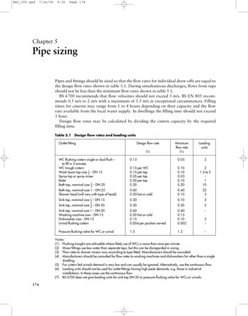
HAC C05.qxd7/24/089:35Page 174Chapter 5Pipe sizingPipes and fittings should be sized so that the flow rates for individual draw-offs are equal tothe design flow rates shown in table 5.1. During simultaneous discharges, flows from tapsshould not be less than the minimum flow rates shown in table 5.1.BS 6700 recommends that flow velocities should not exceed 3 m/s. BS EN 805 recommends 0.5 m/s to 2 m/s with a maximum of 3.5 m/s in exceptional circumstances. Fillingtimes for cisterns may range from 1 to 4 hours depending on their capacity and the flowrate available from the local water supply. In dwellings the filling time should not exceed1 hour.Design flow rates may be calculated by dividing the cistern capacity by the requiredfilling time.Table 5.1Design flow rates and loading unitsOutlet fittingDesign flow ratel/sMinimumflow ratel/sLoadingunitsWC flushing cistern single or dual flush –to fill in 2 minutesWC trough cisternWash basin tap size –12 – DN 15Spray tap or spray mixerBidetBath tap, nominal size –34 – DN 200.130.0520.15 per WC0.15 per tap0.05 per tap0.20 per tap0.300.100.100.030.100.2021.5 to 3–110Bath tap, nominal size 1 – DN 25Shower head (will vary with type of head)0.600.20 hot or cold0.400.10223Sink tap, nominal size –12 – DN 150.200.103Sink tap, nominal size–340.300.205Sink tap, nominal size 1 – DN 20Washing machine size – DN 15Dishwasher size – DN 15Urinal flushing cistern– DN 200.600.20 hot or cold0.150.004 per position served0.400.150.100.002–3–Pressure flushing valve for WC or urinal1.51.2–Notes:(1) Flushing troughs are advisable where likely use of WCs is more than once per minute.(2) Mixer fittings use less water than separate taps, but this can be disregarded in sizing.(3) Flow rates to shower mixers vary according to type fitted. Manufacturers should be consulted.(4) Manufacturers should be consulted for flow rates to washing machines and dishwashers for other than a singledwelling.(5) For cistern fed urinals demand is very low and can usually be ignored. Alternatively, use the continuous flow.(6) Loading units should not be used for outlet fittings having high peak demands, e.g. those in industrialinstallations. In these cases use the continuous flow.(7) BS 6700 does not give loading units for sink tap DN 20 or pressure flushing valve for WCs or urinals.174
HAC C05.qxd7/24/089:35Page 175Pipe Sizing 175Correct pipe sizes will ensure adequate flow rates at appliances and avoid problemscaused by oversizing and undersizing; see figure 5.1.Oversizing will mean: additional and unnecessary installation costs;delays in obtaining hot water at outlets;increased heat losses from hot water distributing pipes.Undersizing may lead to: inadequate delivery from outlets and possibly no delivery at some outlets during simultaneous use;some variation in temperature and pressure at outlets, especially showers and othermixers;some increase in noise levels.(a) flow ratepipe under consideration through at point of delivery(b) available head (pressure)the water main atfromthe storage cistern at pointof delivery headheade.g. 4 mpoint ofdeliveryhead vertical distance in metres from water linein cistern to point under consideration head at main minus height above mainAvailable head 20 m – 4 m(mains supply) 16 m headAvailable head(from cistern)CWSCmaine.g. 20 m headFigure 5.1(c) resistance to flowthrough pipes, valvesand fittingsPipe sizing considerationsIn smaller, straightforward installations such as single dwellings, pipes are often sized onthe basis of experience and convention.In larger and more complex buildings, or with supply pipes that are very long, it is necessary to use a recognized method of calculation such as that shown in sections 5.1 and 5.2.
HAC C05.qxd7/24/089:35Page 176176 Hot and Cold Water SupplyBS EN 806-3 gives an alternative ‘simplified method’ of pipe sizing that can be used for‘standard installations’.5.1Sizing procedure for supply pipesThe procedure below is followed by an explanation of each step with appropriate examples.(1) Assume a pipe diameter.(2) Determine the flow rate:(a) by using loading units;(b) for continuous flows;(c) obtain the design flow rate by adding (a) and (b).(3) Determine the effective pipe length:(d) work out the measured pipe length;(e) work out the equivalent pipe length for fittings;(f) work out the equivalent pipe length for draw-offs;(g) obtain the effective pipe length by adding (d), (e) and (f).(4) Calculate the permissible loss of head:(h) determine the available head:(i) determine the head loss per metre run through pipes;(j) determine the head loss through fittings;(k) calculate the permissible head loss.(5) Determine the pipe diameter:(l) decide whether the assumed pipe size will give the design flow rate in (c) withoutexceeding the permissible head loss in (k).Explanation of the procedureAssume a pipe diameter (1)In pipe sizing it is usual to make an assumption of the expected pipe size and then provewhether or not the assumed size will carry the required flow.Determine the flow rate (2)In most buildings it is unlikely that all the appliances installed will be used simultaneously.As the number of outlets increases the likelihood of them all being used at the same timedecreases. Therefore it is economic sense to design the system for likely peak flows based onprobability theory using loading units, rather than using the possible maximum flow rate.(a) Loading units. A loading unit is a factor or number given to an appliance which relatesthe flow rate at its terminal fitting to the length of time in use and the frequency of usefor a particular type and use of building (probable usage). Loading units for variousappliances are given in table 5.1.By multiplying the number of each type of appliance by its loading unit and addingthe results, a figure for the total loading units can be obtained. This is converted to adesign flow rate using figure 5.2.An example using loading units is given in figure 5.3.
HAC C05.qxd7/24/089:35Page 177Pipe Sizing 1778000(b) Continuous flows. For some appliances, such as automatic flushing cisterns,the flow rate must be considered as a continuous flow instead of applyingprobability theory and using loading units. For such appliances the fulldesign flow rate for the outlet fitting must be used, as given in table 5.1.However, in the example shown in figure 5.3, the continuous flow for thetwo urinals of 0.008 l/s (from table 5.1) is negligible and can be ignored fordesign purposes.(c) Design flow rate. The design flow rate for a pipe is the sum of the flow ratedetermined from loading units (a) and the continuous flows (b).302550002015Determine the effective pipe length (3)(d) Find the measured pipe length. Figure 5.4 is an example showing how themeasured pipe length is found.200010810006 wash basins65 WCscleaners’ sink550042 urinal bowls4003002006 wash basins321.512 wash basins10 WCs2 urinal bowls2 cleaners’ sinks1.0Total loading units0.8Loading units0.60.5200.4100.3Flow rate in litres per second10050sink5 WCs 1 1–22—3 1820—644Therefore, from figure 5.2, the required flow rate for the system is 0.7 l/s.Figure 5.3Example of use of loading unitsAssumed pipe diameter 20 mm.pipe bend1mdouble check valveassemblyFigure 5.2Conversionchart – loadingunits to flow ratestopvalveelbows0.5 m0.25 mdrawofftaps3mMeasured pipe length 4.75 m.NoteFigure 5.4There is no need to consider both branch pipes to taps.Example of measured pipe length
HAC C05.qxd7/24/089:35Page 178178 Hot and Cold Water SupplyTable 5.2Equivalent pipe lengths (copper, stainless steel and plastics)Bore of pipeEquivalent pipe lengthmmElbowmTeemStopvalvemCheck .54.35.66.07.911.5––Notes:(1) For tees consider change of direction only. For gate valves losses are insignificant.(2) For fittings not shown, consult manufacturers if significant head losses are expected.(3) For galvanized steel pipes in a small installation, pipe sizing calculations may be based on the data in thistable for equivalent nominal sizes of smooth bore pipes. For larger installations, data relating specifically togalvanized steel should be used. BS 6700 refers to suitable data in the Plumbing Engineering Services DesignGuide published by the Institute of Plumbing.(e, f) Find the equivalent pipe lengths for fittings and draw-offs. For convenience thefrictional resistances to flow through fittings are expressed in terms of pipe lengthshaving the same resistance to flow as the fitting. Hence the term ‘equivalent pipe length’(see table 5.2).For example, a 20 mm elbow offers the same resistance to flow as a 20 mm pipe0.8 m long.Figure 5.5 shows the equivalent pipe lengths for the fittings in the example in figure 5.4.(g) Effective pipe length. The effective pipe length is the sum of the measured pipe length(d) and the equivalent pipe lengths for fittings (e) and draw-offs (f).Therefore, for the example shown in figure 5.4 the effective pipe length would be:Measured pipe lengthEquivalent pipe lengthselbows 2 0.8tee1 1.0stopvalve1 7.0taps2 3.7check valves 2 4.34.75 m Effective pipe length 30.35 m1.6 m1.0 m7.0 m7.4 m8.6 mPermissible loss of head (pressure) (4)Pressure can be expressed in the following ways.(i)(ii)In pascals, the pascal (Pa) being the SI unit for pressure.As force per unit area, N/m2.1 N/m2 1 pascal (Pa).
HAC C05.qxd7/24/089:35Page 179Pipe Sizing 179Using the example from figure 5.4:20 mm elbow 0.8 m pipe length20 mm tee 1.0 m pipe length20 mm draw-off tap 3.7 m pipe length20 mm stopvalve 7.0 m pipe length20 mm check valve 4.3 m pipe lengthFigure 5.5(iii)(iv)Examples of equivalent pipe lengthsAs a multiple of atmospheric pressure (bar).Atmospheric pressure 100 kN/m2 100 kPa 1 bar.As metres head, that is, the height of the water column from the water level to thedraw-off point.1 m head 9.81 kN/m2 9.81 kPa 98.1 mb.In the sizing of pipes, any of these units can be used. BS 6700 favours the pascal. However, this book retains the use of metres head, giving a more visual indication of pressure thatcompares readily to the height and position of fittings and storage vessels in the building.(h) Available head. This is the static head or pressure at the pipe or fitting under consideration, measured in metres head (see figure 5.1).(i) Head loss through pipes. The loss of head (pressure) through pipes due to frictionalresistance to water flow is directly related to the length of the pipe run and the diameter of the pipe. Pipes of different materials will have different head losses, dependingon the roughness of the bore of the pipe and on the water temperature. Copper,stainless steel and plastics pipes have smooth bores and only pipes of these materialsare considered in this section.(j) Head loss through fittings. In some cases it is preferable to subtract the likely resistances in fittings (particularly draw-offs) from the available head, rather than usingequivalent pipe lengths.Table 5.3 gives typical head losses in taps for average flows compared with equivalent pipe lengths. Figures 5.6 and 5.7 provide a method for determining headlosses through stopvalves and float-operated valves respectively.Note Where meters are installed in a pipeline the loss of head through the metershould be deducted from the available head.
HAC C05.qxd7/24/089:35Page 180180 Hot and Cold Water SupplyTable 5.3Typical head losses and equivalent pipe lengths for tapsNominal size of tapFlow rateHead lossl/smEquivalentpipe lengthmG –12 – DN 150.150.53.7G –12 – DN 150.200.83.7G –34 – DN 200.300.811.8G 1 – DN 0.050.040.03Nominal size of stopvalve0.30.3Flow in litres per second0.4Head loss in metres (wall friction gradient)0.510.60.50.4Note Gate valves and spherical plug valves offer little or no resistanceto flow provided they are fully open.Figure 5.6Head loss through stopvalves
9:35Page 181Pipe Sizing 0.2430.10.080.060.050.040.030.020.01Based on Q AV 0.75V 2gHwhereFigure 5.7Q is flow (l/s)A is cross sectional area of pipe (m2)V is velocity (m/s)g is acceleration due to gravity (m/s2)H is head of water (m)Head loss through float-operated valvesFlow through orifice in litres per second110InchesMillimetres0.60.70.8Diameter of orifice7/24/08Head of water in metres (pressure)HAC C05.qxd
HAC C05.qxd7/24/089:35Page 182182 Hot and Cold Water Supply(k) Permissible head loss. This relates the available head to the frictional resistances in thepipeline. The relationship is given by the formula:Available head (m)Effective pipe length (m)Permissible head loss (m/m run) This formula is used to determine whether the frictional resistance in a pipe will permitthe required flow rate without too much loss of head or pressure. Figure 5.8 illustratesthe permissible head loss for the example in figure 5.4.Pressure at taps 45 m headteedouble check valveassemblyelbowsstopvalvepipe benddraw-offtaps20 mm pipelineFlow rate for 2 taps 0.4 l/sPermissible head loss available head (45 m)effective pipe length (30.55 m) 1.48 m/m runFigure 5.8Example of permissible head lossDetermine the pipe diameter (5)In the example in figure 5.4 a pipe size of 20 mm has been assumed. This pipe size must givethe design flow rate without the permissible head loss being exceeded. If it does not, a freshpipe size must be assumed and the procedure worked through again.Figure 5.9 relates pipe size to flow rate, flow velocity and head loss. Knowing theassumed pipe size and the calculated design flow rate, the flow velocity and the head losscan be found from the figure as follows.(1) Draw a line joining the assumed pipe size (20 mm) and the design flow rate (0.4 l/s).(2) Continue this line across the velocity and head loss
Wash basin tap size 1 . sary to use a recognized method of calculation such as that shown in sections 5.1 and 5.2. HAC_C05.qxd 7/24/08 9:35 Page 175. 176 Hot and Cold Water Supply BS EN 806-3 gives an alternative ‘simplified method’ of pipe sizing that can be used for ‘standard installations’. 5.1 Sizing procedure for supply pipes The procedure below is followed by an explanation of .