Transcription
CD1.1 Tools for PlatinumOperator's GuideDocument No: MAN-EAM-1100Issue F, May 2019Designed and manufactured byGüralp Systems Limited3 Midas House, Calleva ParkAldermaston RG7 8EAEngland
CD1.1 Tools for PlatinumContentsTable of Contents1 Preliminary Notes.51.11.21.31.4Proprietary Notice.5Cautions and Notes.5Manuals and Software.5Conventions.52 Introduction.62.1 Platinum architecture.62.2 CD1.1 architecture.73 The CD1.1 modules.83.1 The CD1.1 multiplexor (data-mux-cd11).83.1.1 Frame assembly time-outs.93.2 The GDI to CD1.1 converter (gdi2cd11).113.2.1 Channel Subframe Status Field.113.3 The CD1.1 receiver (data-in-cd11).143.4 The CD1.1 sender (data-out-cd11).144 Typical configurations.164.14.24.34.4Single seismic station.16Central station of an array.17Handling different frame lengths.17Different frame lengths from one digitiser.185 Using the Multiplexor.195.1 Creating a new multiplexor instance.195.2 Configuration options for the multiplexor.205.2.1 General tab.205.2.2 Subframes tab.21MAN-EAM-1100Issue F - May 2019
CD1.1 Tools for Platinum6 Using the GDI to CD1.1 converter.226.1 Creating a new GDI to CD1.1 converter instance.226.2 Configuration options for the converter.236.2.1 The General tab.236.2.2 Channel map tab.256.2.3 The Calibration tab.266.2.4 The monitoring tab.277 Using the CD1.1 Receiver.307.1 Creating a new CD1.1 receiver instance.307.2 Configuration options for the receiver.317.2.1 The General tab.317.2.2 The Senders tab.337.3 Operation notes.338 Using the CD1.1 Sender.348.1 Back-filling and retransmission.348.2 Creating a new CD1.1 sender instance.358.3 Configuration options for the sender.368.3.1 The General tab.368.3.2 The Channels tab.388.3.3 The Log tab.409 Frame database files.429.1 Managing database files.429.2 Examining database files.4310 Logging and analysing.4410.1 Web-based tools.4410.1.1 Multiplexer log analysis tool.4410.1.2 Receiver log analysis tool.4710.1.3 Sender log analysis tool.4910.2 Command-line tools.5310.2.1 cd11-backfilldb-tool.5410.2.2 cd11-framedb-tool.5610.2.3 cd11-timedb-tool.5710.2.4 cd11-frame-analyser-tool.59MAN-EAM-11003Issue F - May 2019
CD1.1 Tools for Platinum10.2.5 cd11-management-tool.6111 Authentication Management.6311.1 Process Overview.6311.2 Spyrus Lynks operation.6311.2.1 Card initialisation.6411.2.2 Key-pair generation.6511.2.3 Public key retrieval.6511.2.4 Key deletion.6511.2.5 Certificate signing requests.6511.3 CD1.1 operation.6711.3.1 cd11-spyrus-tool.sh.6712 Configuring DM24s and CD24s.7012.1 SoH reporting.7012.2 Latency.7013 Calibration Values.7213.113.213.313.413.513.6Seismic sensors (velocity).73Seismic sensors (acceleration).74Wind speed.75Wind direction.75Acoustic or infrasound sensors.75Temperature.7514 Optional flash memory.7615 File tabase directories.77Inter-process communication.78Configuration.78Run Control.79Miscellaneous.7916 Revision history.81MAN-EAM-11004Issue F - May 2019
CD1.1 Tools for PlatinumPreliminary Notes1 Preliminary Notes1.1 Proprietary NoticeThe information in this document is proprietary to Güralp Systems Limited and maybe copied or distributed for educational and academic purposes but may not be usedcommercially without permission.Whilst every effort is made to ensure the accuracy, completeness and usefulness ofthe information in the document, neither Güralp Systems Limited nor any employeeassumes responsibility or is liable for any incidental or consequential damagesresulting from the use of this document.1.2 Cautions and NotesCautions and notes are displayed and defined as follows:Caution: A yellow triangle indicates a chance of damage to or failure ofthe equipment if the caution is not heeded.Note: A blue circle indicates indicates a procedural or advisory note.1.3 Manuals and SoftwareAll manuals and software referred to in this document are available from the GüralpSystems website: www.guralp.com unless otherwise stated.1.4 ConventionsThroughout this manual, examples are given of command-line interactions. In theseexamples, a fixed-width typeface will be used:Example of the fixed-width typeface used.Commands that you are required to type will be shown in bold:Example of the fixed-width, bold typeface.Where data that you type may vary depending on your individual configuration, suchas parameters to commands, these data are additionally shown in italics:Example of the fixed-width, bold, italic typeface.Putting these together into a single example:System prompt: user input with variable parametersMAN-EAM-11005Issue F - May 2019
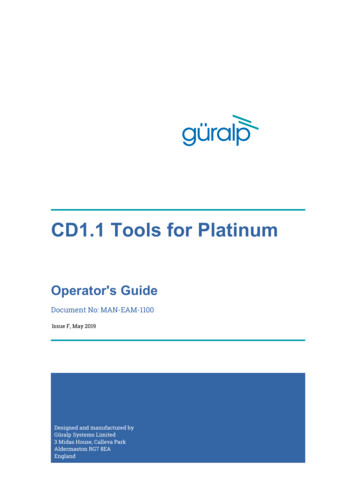
CD1.1 Tools for PlatinumIntroduction2 IntroductionThe Güralp CD1.1 tool suite for the Platinum firmware of Affinity, NAM, and EAMhardware - including *TDE instruments - consists of four modular components thatcan be used together to implement either a single-station CD1.1 sender or a crossarray sender, coalescing subframes from multiple stations into a single outgoingdata frame for the entire array.When building an array, each individual element of the array is actually a fullyindependent CD1.1 sender in its own right.Supported features include fully-conformant status fields (State of Health or SoH),flexible tamper line support, Canadian compression and optional hardwareauthentication. Back-fill capacity is limited only by the size of the fitted flashmodule or disk array.The CD1.1 tool suite runs in parallel to other programs, so it is possible to use otherdata formats simultaneously.2.1 Platinum architecturePlatinum firmware runs natively on the Güralp Affinity, the NAM and the EAM.Instruments such as the 3TDE and 5TCDE have built-in EAMs which run Platinum.Platinum firmware is based on the Linux operating system, which provides a robust,familiar and flexible platform for the protocol-handling and configuration software.Seismic protocols are handled by a number of configurable software modules, whichrun as user-space programs. They can, in general, be stopped, reconfigured andstarted independently of each other. The whole system is managed by a flexible andextensible configuration interface which is accessible in near-identical format fromeither the web interface or a character-based terminal, connected either serially orover a network.The majority of the protocol-handling features of Platinum are based on Güralp DataInterconnect, or GDI. The gdi-base module serves as the central data interchange,accepting data from a wide variety of input protocol-conversion modules, bufferingand re-ordering incoming data where necessary, associating samples with theirmeta-data and providing data via a consistent interface to the output protocolconversion modules.It is possible to use CD1.1 under Platinum without using GDI but, if any data receivedin different formats are to be converted to CD1.1, they will first be converted to GDIand passed via the gdi-base module.For pure CD1.1 implementations, it is neither efficient nor necessary to convert to andfrom GDI, so a separate CD1.1 multiplexor module is provided. Incoming CD1.1 framesare not passed to GDI, so it is not possible to convert them into non-CD1.1 formats,such as SEEDlink.MAN-EAM-11006Issue F - May 2019
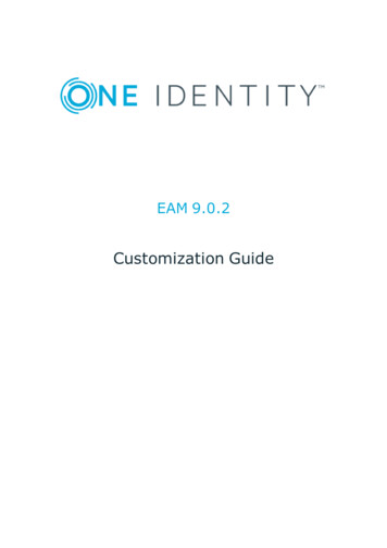
CD1.1 Tools for PlatinumIntroduction2.2 CD1.1 architectureThe CD1.1 tool suite consists of four primary modules: The CD1.1 receiver (data-in-cd11), which receives data in CD1.1. format fromexternal CD1.1 data producers (DPs); The GDI to CD1.1 converter (gdi2cd11), which receives data from GDI and, thus,indirectly, from any other source in any supported format; The CD1.1 multiplexer (data-mux-cd11), which accepts and combines datafrom one or more instances of the previous two modules; and The CD1.1 sender (data-out-cd11), which takes data from a CD1.1 multiplexerinstance and transmits them in CD1.1 format to external CD1.1 data consumers(DCs).Any useful configuration will, therefore, use at least three of these modules. It ispossible to configure more than one instance of any of these modules and these canbe connected together as necessary when building more complex implementations.The diagram, above, shows a simple configuration using all four CD1.1 modules. It isnecessary to use either the CD1.1 Receiver (data-in-cd11) or the GDI to CD1.1converter (gdi2cd11) but not you do not need to use both.The diagram also shows the subframe database which stores all subframes passingthrough. These can then be used to satisfy back-fill requirements andretransmission requests from external receivers. This database can be located eitherin flash RAM or on a hard drive, depending on considerations of storage space andpower consumption.The data paths between modules are implemented using POSIX local IPC sockets.The following sections provide an introduction to how each module works. Typicalconfigurations will then be discussed, followed by a detailed description of eachmodule's instantiation, configuration and use.MAN-EAM-11007Issue F - May 2019
CD1.1 Tools for PlatinumThe CD1.1 modules3 The CD1.1 modulesThis section of the manual will describe the function of each of the four CD1.1modules in detail. For precise configuration instructions, please refer to sections 5through 8.3.1 The CD1.1 multiplexor (data-mux-cd11)This is the central store-and-forward module for CD1.1 subframes. Every CD1.1configuration requires at least one CD1.1 multiplexor instance to be active. Aninstance of this module must be configured before the configuration system willallow any other CD1.1 modules to be instantiated.CD1.1 subframes originating from either external CD1.1 sources (via data-in-cd11)or from non-CD1.1 sources (via gdi2cd11) are transmitted to this module. Themultiplexor stores these subframes, either on disk or in flash RAM, and willcoalesces frames from multiple sources where this is appropriate. It then forwardscomplete data frames onwards to the output stage, data-out-cd11.Subframes are stored briefly before they are assembled into frames. There is a tradeoff between the data latency - the amount of time between a subframe's receptionand its transmission as part of a frame - and the overall framing efficiency - thenumber of subframes that can be packed into a single frame. A parametrisedalgorithm is used to allow the operator to tune this to suit each application's specificrequirements - see section 3.1.1 on page 9 for more details.The multiplexor is responsible for responding to retransmission requests arrivingfrom external receivers via a data-out-cd11 instance. The subframe store is usedto satisfy these requests. An interactive logging tool is provided to allow theoperator to query and inspect the contents of the store.One storage file is created per day. To limit the amount of back-fill being stored, adirectory cleaner task must be set up to remove unwanted storage files.MAN-EAM-11008Issue F - May 2019
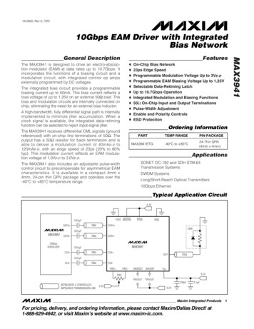
CD1.1 Tools for PlatinumThe CD1.1 modules3.1.1 Frame assembly time-outsTwo separate time-out parameters are used to control the assembly of relatedsubframes into frames: one for real-time data and one for back-filled data.In complex networks, data may arrive from a number of CD1.1 data producers (DPs)along diverse routes, each with different transmission latencies. DPs may be addedand removed at any time and communications may be interrupted for short or longperiods. A dropped link or a decommissioned station should not interrupt the flowof data from other stations. Because of this, the frame assembly algorithm does notand, indeed, cannot know how many subframes it should expect for any given timestamp. It is therefore necessary to use time-outs when assembling subframes intoframes.As an example, let us consider a hypothetical array with three remote sensorstations functioning as CD1.1 DPs, all of which use ten-second subframes, and acentral data consolidation station. The transmission times of the three links to thecentral station are, say, one, two and three seconds. The real-time data time-out atthe central station will be set to three seconds.At some time, T0, each station begins assembling samples into subframes and, ataround T0 10 seconds, they all transmit their completed subframes to the station.Each subframe is labelled with the time-stamp of its first sample: T 0.At T0 11 seconds, the first subframe arrives at the station. The multiplexer inspectsthe time-stamp and, as it has not seen any subframes labelled T 0 before, it stores thesubframe in a new collection, labelled T0, and sets an alarm (specific to thiscollection) for the current time (T0 11) plus the time-out - i.e. T0 14 seconds.At T0 12 seconds, the second subframe arrives at the station. The multiplexerinspects the time-stamp and places the subframe in the existing T 0 collection. At T0 13 seconds, the third subframe arrives and is treated identically. At this point, themultiplexer does not know that it has received all the subframes, so it carries onwaiting.At T0 14 seconds, the alarm for this collection fires and the multiplexer assemblesall the subframes from the T0 collection into a frame and passes it to the data-outMAN-EAM-11009Issue F - May 2019
CD1.1 Tools for PlatinumThe CD1.1 modulescd11 module(s). The collection is moved to the data store and is no longerconsidered active.Now consider the case where the third communication link is interrupted for, say,five seconds, starting at T0 10. The first and second subframes will arrive as beforeand, at T0 14 seconds, they will be assembled into a frame and transmitted.One second later, at T0 15 seconds, the link is restored and the third subframe istransmitted. It will arrive at T0 18 seconds. The multiplexer inspects the timestamp and, as it has no longer has an active collection labelled T 0, it stores thesubframe in a new collection, also labelled T 0, and sets an alarm (specific to thiscollection) for the current time (T0 18 seconds) plus the time-out - i.e. T0 21seconds. No more packets labelled T0 will arrive so, when the alarm fires, the lonesubframe will be wrapped up as a frame and transmitted on its own.If the time-out had been set to eight seconds, the delayed subframe would havearrived in time to be sent along with the other two: the packing efficiency wouldhave been improved but, as the completed frame would not have been transmitteduntil T0 19 seconds, the overall latency would have increased. The time-out shouldthus be adjusted to achieve the desired trade-off between subframe packingefficiency and overall data latency.Where back-filled subframes are involved, it is assumed that latency is of lesserconcern - the data are already significantly delayed - and packing efficiency isconsidered more important. For this reason, although the algorithm is identical, aseparately configurable time-out is provided which only applies to back-fill frames.It is expected that this time-out will normally be set to a significantly higher valuethan the live data time-out.MAN-EAM-110010Issue F - May 2019
CD1.1 Tools for PlatinumThe CD1.1 modules3.2 The GDI to CD1.1 converter (gdi2cd11)This module is used to encode data from non-CD1.1 sources into standards-compliantCD1.1 subframes. It should be used, for example, when data from directly attacheddigitisers and digital instruments are to be transmitted using CD1.1.The subframes contain a number of additional data beside the samples: Channel meta-data is used to populate the “instrument type” and “gain”fields The “channel status” field is populated using information from the stateof-health data provided by gdi-base, from the anti-tamper lines (andother digital input/output fields) and from the internal temperature andvoltage monitoring subsystems. Optionally, a cryptographic signature generated by a hardware engine(such as the Spyrus encryption card). Operation of such hardware isdiscussed in chapter 11 on page 63.The subframes can support any sample rate and can be of various durations (inmultiples of 10 seconds).3.2.1 Channel Subframe Status FieldThe gdi2cd11 module implements the first permitted status field as defined withformat value 1 in the CTBTO standard revision 0.2. There are several reserved bitsand bytes in the standard, and these can optionally be mapped to additional detailsin the gdi2cd11 configuration (see section 6.2.4 on page 27).MAN-EAM-110011Issue F - May 2019
CD1.1 Tools for PlatinumThe CD1.1 modulesThe meaning of the bits is mapped as follows (counting from 1, with 1 being the leastsignificant bit and 8 the most):Byte(s)Bit(s)21Dead sensor channelNot used2Zeroed dataNot used3ClippedNot used4Calibration under waySet when calibration is inprogress on associatedcomponent1Equipment housing openConfigurable tamper monitor2Digitiser openConfigurable tamper monitor3Vault door openedConfigurable tamper monitor4Authentication seal brokenConfigurable tamper monitor5Equipment movedConfigurable tamper monitorFuture useConfigurable tamper monitors1Clock diff. too largeSet if clock difference 1000µs(configurable)2GNSS receiver offSet if ADC module reports nocommunication from GNSS, orGPS power is off3GNSS receiver unlockedSet if ADC module reports clock isnot phase locked to GNSS PPSsignal4analogue input shortedNot used5Calibration loop backNot usedFuture useNot used1Main power failureConfigurable; set if voltage ofchosen line drops below specifiedvalue2Backup power unstableConfigurable; set if voltage ofchosen line drops below specifiedvalue (independent from mainpower failure bit)3–8Future useNot used1–8UndefinedConfigurable; 8-bit voltage,temperature, power or currentreading sue F - May 2019
CD1.1 Tools for PlatinumThe CD1.1 nedConfigurable; 8-bit voltage,temperature, power or currentreading #281–8UndefinedConfigurable; 8-bit voltage,temperature, power or currentreading #39–28Time of last GNSSsynchronisationMost recent reported lock fromADC module, invalid ( year 2000)if never locked.29–32Clock differential inmicrosecondsIf clock is locked, this is themeasured difference between theADC's sample clock and the GNSSPPS line in µs. If unlocked, it isan estimate (magnitude, soalways positive) of the drift basedon the measured worst-case driftof the ADC's crystal.Bytes 6, 7 and 8 of the status field can optionally be used to monitor line voltage,power or current flow, or temperature. As there are only 8 bits available, the scalesfor the value are complex and must be manually configured by the operator in orderto get the best range available. Values that are outside what can be represented areclipped at 0 or 255 (not aliased).The voltage scale allows a value between 5.0 and 30.5 to be represented with 0.1increments. To convert from the unsigned byte value x to an analogue value, use:y 5.0 (0.1 x )The power or temperature scale allows a value between -64 and 63.5 to berepresented with 0.5 increments. Note that EAM modules measure incoming poweras positive, and outgoing power as negative. To convert from the signed byte value xto an analogue value, use:y x 0.5To convert from the unsigned byte value u to an analogue value, use:u 128 :u 128 :y u 0.5y (u 256) 0.5The current scale allows a value between -1.28 and 1.27 to be represented with 0.01increments. Note that EAM modules measure incoming current as positive, andoutgoing current as negative. To convert from the signed byte value x to an analoguevalue, use:y x 0.01MAN-EAM-110013Issue F - May 2019
CD1.1 Tools for PlatinumThe CD1.1 modulesTo convert from the unsigned byte value u to an analogue value, use:u 128 :u 128 :y u 0.01y (u 256) 0.013.3 The CD1.1 receiver (data-in-cd11)This module receives CD1.1 frames from external CD1.1 senders (DPs). It is typicallyused at an array data centre, where it receives data frames from any CD1.1 senders inthe array; typically each array element or station will have its own CD1.1 sender.The receiver is fully standards-compliant, although it has no support for validatingincoming signatures.The receiver can accept connections and data from multiple, simultaneous, remoteDPs. It correctly identifies and requests re-transmission of missing data frames byissuing CD1.1 acknack frames.Note: Unlike other Platinum data reception modules, the CD1.1 receivermodule does not currently alter or decode any subframes it receives and itdoes not pass them to gdi-base: they are passed on unaltered and onlyto the CD1.1 multiplexor module.3.4 The CD1.1 sender (data-out-cd11)This module is a fully standards-compliant CD1.1 sender (DP). It is responsible for: Receiving CD1.1 channel subframes from the multiplexor; Assembling them into full CD1.1 frames; Transmitting them over a TCP network to a remote receiver (DC); Handling retransmission requests originating from its clients;MAN-EAM-110014Issue F - May 2019
CD1.1 Tools for PlatinumThe CD1.1 modules Monitoring the transmission log to determine whether any gaps haveoccurred (for example, due to re-starting of the sender process) and, if so,transmitting the missing packets (back-fill); Logging all transmissions to a “frame list” held on local disk or Flashmemory; and, optionally, Digitally signing the frames using an optional hardware encryption engine(see chapter 11 on page 63).A CD1.1 sender module can only transmit to a single Data Consumer (DC). If there is arequirement to support multiple DCs, multiple sender module instances are needed.Each can send a different set of subframes, if required.Because the multiplexer supports multiple senders, it is more efficient fortransmitted frames to be stored by the multiplexer, rather than by the sender. Thisavoids having to store the same frame multiple times. However, because the framenumbering of outgoing frames is connection specific, the multiplexer cannot knowthese numbers and it stores frames by time-stamp, rather than by frame number.The sender keeps track of which frame is which by storing a database of framenumbers against timestamps. This database is consulted when the sender receivesan acknack frame, so that it can request the corre
MAN-EAM-1100 5 Issue F - May 2019. CD1.1 Tools for Platinum Introduction 2 Introduction The Güralp CD1.1 tool suite for the Platinum firmware of Affinity, NAM, and EAM hardware - including *TDE instruments - consists of four modular components that


![FIPS 140-2 Non-Proprietary Security Policy Acme Packet 1100 [1] and .](/img/49/140sp3490-5601486.jpg)