Transcription
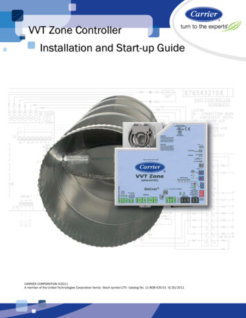
VVT Zone ControllerInstallation and Start-up GuideCARRIER CORPORATION 2011A member of the United Technologies Corporation family · Stock symbol UTX · Catalog No. 11-808-435-01 · 6/20/2011
Table of ContentsIntroduction . 1What is a VVT Zone Controller? .1Specifications .3Safety Considerations .5Installation . 6Field-supplied hardware .6Mounting the VVT Zone Controller .7To mount the controller . 7Wiring the VVT Zone Controller for power .8To wire the controller for power . 9To address the VVT Zone Controller .9Wiring the VVT Zone Controller to the MS/TP network . 10Wiring specifications . 10To wire the controller to the network . 10Wiring sensors to inputs . 11Wiring an SPT sensor . 12Rnet wiring specifications . 12To wire the SPT sensor to the controller . 13Wiring a T55 space temperature sensor . 14Wiring specifications . 14To wire the T55 sensor to the controller . 14Wiring a Supply Air Temperature sensor . 15Wiring specifications . 15To wire the SAT sensor to the controller . 15Wiring a Duct Air Temperature sensor . 16Wiring specifications . 16To wire the DAT sensor to the controller . 16Wiring a CO2 sensor. 17Wiring specifications . 17To wire the CO2 sensor to the controller . 17Wiring a Relative Humidity sensor . 19Wiring specifications . 19To wire the RH sensor to the controller. 20Wiring a remote occupancy sensor . 20Wiring specifications . 21Wiring equipment to outputs . 21Wiring specifications . 21Wiring diagram legend . 22Single duct only . 22Single duct 2-position hot water. 23Single duct modulating hot water . 23Single duct combination base board and ducted heat . 24Single duct 2-stage electric heat . 24Fan box 2-position hot water . 25Fan box modulating hot water - ducted or baseboard . 25Fan box combination baseboard and ducted heat . 26Fan box 2-stage electric heat . 26Wiring field-supplied actuators to the analog output . 27High-torque actuators . 27Linked actuators. 28VVT Zone Controlleri
Table of ContentsStart-up . 29Configuring the VVT Zone Controller's properties . 29Unit Configuration properties . 30Setpoint properties. 30Service Configuration properties . 33Linkage properties . 34Performing system checkout . 35Commissioning the VVT Zone Controller . 36Balancing the system. 36Step 1: Prepare for balancing. 37Step 2: Balance each zone . 37Step 3: Set the system static pressure . 38Sequence of operation . 40Temperature sensors . 40Zone airflow control. 41Zone reheat control . 42Demand control ventilation (DCV) and dehumidification using optional sensors . 43Occupancy. 44Alarms . 45Demand limiting . 46Linkage . 46Air source mode determination. 47Troubleshooting . 48LED's . 48Serial number . 49Replacing the VVT Zone Controller's battery . 49Compliance . 50FCC Compliance . 50CE Compliance . 50BACnet Compliance. 50Appendix A: VVT Zone Controller Points/Properties . 51Status. 51Unit Configuration . 52Setpoints . 53Alarm Configuration . 58Service Configuration . 60Maintenance . 63Alarms . 65Linkage . 65I/O Points . 67Appendix B: VVT terminal modes . 69Index . 71iiVVT Zone Controller
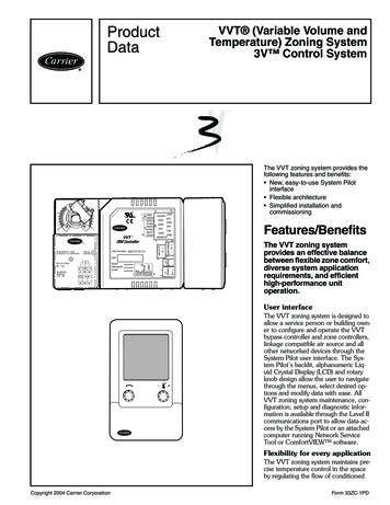
The VVT Zone Controller with built-in actuator maintains zone temperature by operating the terminal fan and regulating the flow of conditioned air into the space. Buildings with diverse loading conditions can be supported by controlling the air source heating and cooling sources or supplemental heat. The VVT ZoneFile Size: 1MBPage Count: 80