Transcription
2010 Cobra Jet Owner's GuideThis is a Racing Vehicle!! This vehicle is intended for offroad use ONLY and is not legal for on-road use!The Cobra Jet is a turn-key, or in this case a push button, racing vehicle and requires proper racepreparation. Please read and understand the owner's guide and the detailed instructions for the variouscomponents supplied with your Cobra Jet. Beyond component specific maintenance we recommend thatyou regularly "nut and bolt" your Cobra Jet. This is a process of checking all the nuts, bolts, wiring, belts,hoses, tires, etc on your vehicle. An example of the importance of this is your vehicles tire pressures.Drag racing tires tend to leak over time and, or change just by sitting in the sun for an extended time andwill need to be checked before every run. Please be diligent with the care of your vehicle!Vehicle InformationStart-Up ProcessAttention: After start-up, prior to any runs, take the time to properly break-in your brake system. It is asimple procedure that is required and will save you time and grief. Make nine total stops to three differentprogressively higher speeds starting with 30 mph, then 50 mph and 75 mph. Allow the brakes to coolslightly between each run without applying pressure to the pedal between runs. After the last stop, allowthe brakes to completely cool before making your initial run on your vehicle.Automatic Equipped Vehicles, C4 and Cruise-O-MaticTurn on the Cobra Jet's electrical system by pulling out the master cut-off switch located on thepassenger rear quarter panel. Once in the driver seat, turn on the first three switches on the centerconsole, you will notice the lights go on above the switches. The first switch is ignition, the second isintercooler fan and the third is fuel pump. You should hear the intercooler fan start as it is switched on. Ifnot, stop and investigate before going forward. Serious damage may occur to the engine if the intercooleris not functioning.Make certain that the transmission is in park, pushed all the way forward. If the transmission is in neutralor in gear, move the lever forward until you hit a detent, this will be neutral. To engage park, move thechrome lever on the side of the shifter up and push forward on the shift lever. The shifter is now inreverse. Grasp the chrome handle on the shifter and move the lever forward, this will be park.Apply pressure to the brake and push the start engine button in the center of the instrument panel.1
The C4 Transmission is a reverse valve body, meaning first gear is in the first position back from neutral,then second and third in order, again moving back.The Cruise-O-Matic Transmission is standard valve body, meaning first gear is in the second positionback from neutral, second gear or high gear is in the first position back from neutral.TR6060 Equipped VehiclesTurn on the Cobra Jet's electrical system by pulling out the master cut-off switch located on thepassenger rear quarter panel. Once in the driver seat, turn on the first three switches on the centerconsole, you will notice the lights go on above the switches. The first switch is ignition, the second isintercooler fan and the third is fuel pump. You should hear the intercooler fan start as it is switched on. Ifnot, stop and investigate before going forward. Serious damage may occur to the engine if the intercooleris not functioning.Make certain that the transmission is in neutral. The TR6060 has a standard six speed pattern withreverse being to right and up. Push in the clutch and push the start engine button in the center of theinstrument panel.LSC5100 Equipped VehiclesTurn on the Cobra Jet's electrical system by pulling out the master cut-off switch located on thepassenger rear quarter panel. Once in the driver seat, turn on the first three switches on the centerconsole, you will notice the lights go on above the switches. The first switch is ignition, the second isintercooler fan and the third is fuel pump. You should hear the intercooler fan start as it is switched on. Ifnot, stop and investigate before going forward. Serious damage may occur to the engine if the intercooleris not functioning.You should be able to move the shift lever forward and backward with neutral being the center of travel.Make certain that it is in the neutral gate, center of travel. Push in the clutch and push the start enginebutton in the center of the instrument panel.Select first gear by -Pull up on the perpendicular lever while in the neutral gate-Push forward on handleIf the shifter feels like it will not go into first gear, bump the clutch pedal while applying forward pressure.For second through fifth, do not touch the perpendicular lever. Pull back and forth on the handle as yougo up through the gears. CAUTION - do not down shift this transmission as you would a fullysynchronized transmission. It is fully face plated and will be damaged if down shifting occurs withoutmatching gear speeds. For reverse, push down on the perpendicular lever while in the neutral gate andpull back into the bottom position. If the shifter feels like it will not go into reverse, bump the clutch pedalwhile applying rearward pressure.2
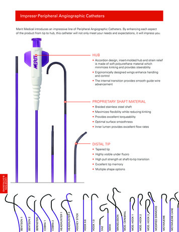
Electrical systemsAdditional information can be found ionsheets/FordInstShtM-6017-463V 54SC.pdfOBDII ConnectorLocated under the passenger side air bag cover.Controls Pack Power Distribution BoxThe Controls Pack Power Distribution Box (PDB) is located under the passenger side air bag cover. ThisPDB is sold as part of the Ford Racing Controls Pack M-6017-54SC and contains fuses/relays requiredfor base engine control. Refer to schematics at the end of this document for fuse/relay locations withinthis PDB.Fuel Pump In-Line Fuse and RelayIn order to minimize voltage drop between the battery and fuel pump, the fuel pump power feed is routeddirectly from the master power to the fuel pump relay in the trunk. Since this wire is not routed through aPDB, a separate in-line fuse and relay is used. The in-line fuse is located next to the master cutoffswitch, located inside the trunk, passenger side. The relay is located next to the fuel pump, also in thetrunk.3
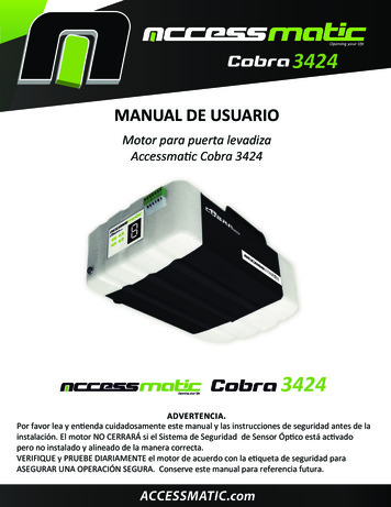
Vehicle Power Distribution BoxThe Vehicle PDB shown in the following picture contains fuses/relays used for headlights, taillights and allother vehicle functions. It also contains the fuse and relay for Intercooler pump and intercooler fancontrol. The PDB is located in the passenger side glove box. Refer to schematics at the end of thisdocument for fuse/relay locations within this PDB.Center ConsoleThe center console contains the Oil Pressure, Fuel Pressure and Engine Coolant Temperature gauges.Additional information on these gauges is available from Autometer athttp://www.autometer.com/tech instructions.aspx. Multiple switches are located below these gauges forcontrol of ignition, fuel pump, and intercooler. In general, the lamps above each switch will illuminatewhen the switch is placed in the ON position. The one exception to this is the intercooler pump lampwhich turns on any time the intercooler pump is activated by either the Powertrain Control Module (PCM)or by manually placing the switch in the ON position. The main function of this switch is to turn on theintercooler pump when the engine is not running.Future ExpansionThree fused 10Amp circuits are available on the center console for addition of customer accessories suchas data loggers, radios, etc. These circuits can be accessed by removing the center console and addingthe circuit to the output side of the desired switch. One of the circuits uses 12V Hot At All Times (HAAT)power while the other two circuits interface to Run/Start (R/S) Power and will only provide power when theignition switch is in the ON position.Power WindowsThe power window control includes a feature to move the window down slightly if the door is opened withthe window in the fully raised position. After extended periods of time with the master switch in the offposition, the window may need to be operated through one complete up/down cycle to recalibrate the4
window position controller for full up/down position. After one complete cycle is accomplished the powerwindows will function normally until the master power is turned off again.Wheel Speed MeasurementA variable reluctance sensor is mounted in the right front caliper adapter for measurement of vehiclespeed (VS). VS is an input for launch control and disables launch control operation once VS is non-zero.EnginesBase; 5.4L TVS 2.3L Supercharger, 4.6L, 352cid, 428cidUpgrade; 5.4 L Whipple 4.0L SuperchargerTransmissionsC4Joel's on Joy transmissionReverse valve bodyPattern P-R-N-1-2-3Line lock switch integrated into shifter KnobBiondo switch functioned launch controlCruise-O-MaticJoel's on Joy transmissionPattern P-R-N-2-1Reverse lock outBiondo switch functioned reverse and launch controlLine lock switch integrated into shifter KnobNote: Do not hold down Biondo switch for more than 30 seconds at a time, failure to thetransmission brake may occur.TR6060Production based TR6060Integrated QuickTime bell housingLiberty's Gears shifter handle with integrated line lock switchLSC5100Liberty's Gears transmissionV-Gate shifter with integrated line lock switchClutch SystemsTR6060Centerforce non-adjustable, www.centerforce.comLSC5100Ram Clutches 10" billet, six stand, adjustable base and counterweight unit, www.ramclutches.comNote: Vehicles are delivered with five turns of base and no counterweight. This is a veryaggressive set up to ensure that premature clutch failure doesn't occur. Vehicles are alsodelivered with a ring height gage and a counterweight kit.5
Launch ControlThe 2010 Cobra Jet has an industry first, integrated launch control that will maintain a set engine speedwhile the accelerator pedal is depressed. This feature is built into the powertrain control module (PCM)and does not require aftermarket components. There are three aspects of the launch control:1. Launch control indicator2. Setting of the desired launch engine speed3. Activating the launch control at the starting lineNOTE: All indications of RPM are only displayed on the production tachometer in the instrumentcluster. The Ford Racing tachometer will not display any information for the launch controlfeature.Launch Control RPM IndicatorThe launch control will display the current RPM set point after a PCM power up. When the ignition switchis turned "ON", the in dash tachometer will sweep from 0 to 8000 and back to 0. Then the launch controlwill sweep the tachometer to the current launch control RPM setting for approximately 2 seconds as anindication to the driver the current launch control set point. The tachometer will then return to 0 indicatingthe current engine speed.Launch Control RPM SettingThe launch control utilizes the production speed control buttons in the steering wheel to set the desiredlaunch engine speed. Proper precautions have been made to ensure the launch control setting modecannot be entered unless the vehicle is stopped, however, the engine can be running or off. To set thelaunch control RPM, a simple 3 step process is required:1. Depress the brake pedal and simultaneously hold the speed control "ON" button forapproximately 2 seconds. The in dash tachometer will sweep from the current engine speed (0 ifthe engine is off) to 8000 and back to the current launch control set point. After the tachometersweeps and is displaying the current set point, release the "ON" button. The brake pedal can alsobe released and is not necessary for the rest of the procedure.6
2. The launch control RPM point is increased by pressing the "SET " or decreased by pressing the"SET –" speed control buttons. The RPM will change in 100 RPM increments. The user range forthe launch control is 2000 rpm to 7000 rpm and the PCM will not allow any settings beyond theselimits.3. Once the desired launch control set point is achieved, press the "RESUME" speed control button.The in dash tachometer will again sweep to 8000 rpm, back to the desired set point, and finallyback to the current engine speed (0 if the engine is off). This launch control set point is nowstored in the PCM's non-volatile memory and will maintain this value until it is changed againeven if the power is removed from the PCM.Disabling Launch ControlThe launch control can be completely disabled by following the following steps:1. Depress the brake pedal and simultaneously hold the speed control "OFF" button forapproximately 2 seconds. The in dash tachometer will sweep from the current engine speed (0 ifthe engine is off) to 8000 and back to the current engine speed (0 if the engine is off). After the indash tachometer sweeps back to the current engine speed, release the "OFF" button. The launchcontrol is now disabled. To enable the launch control, follow the launch control RPM setting stepsagain.Launch Control ActivationLaunch control activation is slightly different between the manual transmission and automatictransmission vehicles.Manual Transmission VehiclesVehicles equipped with the manual transmission have a clutch switch which indicates when the clutchpedal is the top of its travel. The PCM knows when to engage the launch control based on a signal fromthe clutch switch indicating the clutch in engaged. There are three conditions that must be satisfied toengage the launch control RPM limiter.7
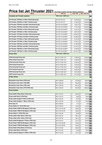
1. The clutch must be depressed2. The vehicle speed must be less than 0.5 mph3. The launch control must be turned on by the user using the speed control switches. See "LaunchControl RPM Setting" above.Automatic Transmission VehiclesVehicles equipped with the automatic transmissions have a Biondo push button switch next to the shifterin the console. The PCM knows when to engage the launch control based on a signal from the Biondoswitch. There are three conditions that must be satisfied to engage the launch control RPM limiter.1. The Biondo switch must be depressed2. The vehicle speed must be less than 0.5 mph3. The launch control must be turned on by the user using the speed control switches. See "LaunchControl RPM Setting" above.NOTE: Only the Cruise-O-Matic (2 speed) automatic transmissions are equipped with a trans brakewhich will be engaged with the Biondo switch. The C4 (3 speed) transmissions are not equippedwith a trans brake.Biondo SwitchThe Biondo switch is used to help adjust reaction time when using launch control. With the switchadjusted to full down position, reaction times will be slowed. With it adjusted to the full up position, theywill quicken.Full DownFull UpBrakesAttention: The Strange Engineering brake kit on the Cobra Jet is designed for Drag Racing only!www.strangeengineering.net8
Break-In ProcedureMake nine total stops to three different progressively higher speeds starting with 30 mph, then 50 mphand finely 75 mph. Allow the brakes to cool slightly between each run without applying pressure to thepedal between runs. After the last stop, allow the brakes to completely cool before making your initial runon your vehicle. Follow the same procedure when installing new brake pads or rotors.Proportioning ValveWith the valve rotated clockwise until seated, the rear calipers will have full pressure. With the valverotated counterclockwise full out, the rear caliper pressure will be reduced by 57%. The vehicle isdelivered with a setting of 5 rotations out from seated.Fuel Sample PortThe fuel sample port is mounted to the fuel pressure regulator located on the passenger side, front innerwheel well.Taking a sample will require a length of 5/32" fuel proof rubber hose to reach whatever vessel being usedto hold the sample. After installing the sample hose, with the vehicle master cutoff switch on, turn on the9
fuel pump, turn the valve to the on position and depress valve for flow. Once the required amount of fuelis obtained, release valve, rotate to the off position, and turn off the fuel pump and main power switches.Remove the sample hose.DampersThe front and rear dampers are manufactured by Tokico/Dynamic Suspensions. They are adjustable witha range from zero to eight turns out. Zero or clockwise rotation until seated is full stiff. Do not forceadjuster beyond initial contact with stop, damage to the seat will occur. Eight turns out counterclockwise from seated is full soft. Do not rotate beyond this point.Seat BeltsAttention: The seat belts in the Cobra Jet are NOT PRE SET. Before driving the vehicle, set beltlengths. They will need to be adjusted for each individual that races this vehicle.Pro Cal ToolTo receive a MMC (Multi Media Card) for the Pro Cal Tool, the vehicle registration form must be returnedto Ford Racing. If you have any questions on this process, please contact the Ford Racing Techline at800-367-3788.Tire Care, Off SeasonTips from the Hoosier web site:1. Remove the tires from the vehicle.2. Remove the air from the tires and store them on their side in a cool/dark/dry environment.3. Place tires in a black plastic bag when stored during the "off-season".4. Make sure the temperature range in the storage location is between 40-90 degrees Fahrenheit.For additional information visit www.hoosiertire.comVehicle Tie DownsThis vehicle is equipped with both front and rear tie down locations along with a tow hook location.Front Tie Down and Tow Hook Location10
Rear Tie Down LocationMaintenance and SpecificationsFuelRockett Brand 118 Racing Fuel, www.rockettbrand.comEngine OilAll engine options; Motorcraft 5W-50 Full Synthetic XO-5W50-QGTOil Filter4.6L /5.4L: Ford Racing M-6731-FL820 (case of 12), 352cid/428cid: Ford Racing M-6731-FL1A (case of 12)Engine & Intercooler CoolantMotorcraft Premium Gold with Bittering Agent WSS-M97B51-A1Transmission OilC4 & Cruise-O-MaticXT-1QF Motorcraft Type FLSC 5100Liberty's Gears Synthetic SAE 80W-140 LGX-80TTC TR6060XT-2-QDX Mercon ATFSupercharger OilMotorcraft XL4Differential OilLucas High Performance Heavy Duty SAE 85W-140 Gear OilBrake FluidHigh Performance DOT3 PM-1-CTires SizesFront; Hoosier 26/4.5-15Rear; Base Engines, Manual and Automatic Vehicles, Hoosier 30/9-15Upgraded Engine, Manual Vehicles, Hoosier 29/11-15Upgraded Engine, Automatic Vehicles, Hoosier 30/10.5-15Air FilterBase Engines; 5.4L: M-9601-D, 4.6L: M-9601-B, 352cid/428cid: M-9601-CJUpgrade 5.4L; Whipple R0298-911
Fuel FilterAeromotiveTM 10 micron #12601Spark PlugsNGK TR7 gapped to .035"Vehicles are delivered with Motorcraft spark plugs and should be changed at the owner's earliestconvenience. They have a limited life expectancy, 7-10 runs. Once NGK spark plugs are installed, uponany misfire, they should be changed.EngineDrag racing puts extreme loads on engine components that will require unique maintenance performedon a regular basis. Ford Racing recommends the following:1. Change engine oil and filter after every two to three weekend events, cut open filter and inspectfor foreign material.2. Monitor engine oil pressure over time to understand engine bearing wear by picking a consistentRPM and temperature to look for deviations.3. Check cylinder compression and leakage after every two to three weekend events to monitorengine condition.Vehicle Set UpFuel Pressure, Base & Upgrade62 2 psi gage, fuel pump on and engine offChassis Set UpDamper Settings;Front; 6 turns outRear; 3 turns outPinion Angle; -2.5 0.5 Caster; 7.1 0.75 Camber; 0.75 0.75 Toe; -1/16" to -1/8" per side (measured @ center line of wheel flange, 15")Anti-Roll Bar, Rear; 200 lb more on left rear tire with driver in seat, this is adjusted by rotating the right orleft drop link.TiresStarting PressuresFront; Hoosier 35 psiRear; Manual Vehicles, Hoosier Bias 13 psiAutomatic Vehicles, Hoosier Radial 15 psi12
Launch Control The 2010 Cobra Jet has an industry first, integrated launch control that will maintain a set engine speed while the accelerator pedal is depressed. This feature is built into the powertrain control module (PCM) and does not require aftermarket components. There are three aspects of the launch control: 1. Launch control indicator 2.