Transcription
A cement and concrete industry publicationHow to Design ConcreteStructures using Eurocode 2A J Bond MA MSc DIC PhD MICE CEngO Brooker BEng CEng MICE MIStructEA J Harris BSc MSc DIC MICE CEng FGST Harrison BSc PhD CEng MICE FICTR M Moss BSc PhD DIC CEng MICE MIStructER S Narayanan FREngR Webster CEng FIStructE
ForewordThe introduction of European standards to UK construction is a significant event. The ten design standards, knownas the Eurocodes, will affect all design and construction activities as current British Standards for design are dueto be withdrawn in 2010 at the latest. BS 8110, however, has an earlier withdrawal date of March 2008. The aimof this publication is to make the transition to Eurocode 2: Design of concrete structures as easy as possible bydrawing together in one place key information and commentary required for the design and detailing of typicalconcrete elements.The cement and concrete industry recognised that a substantial effort was required to ensure that the UK designprofession would be able to use Eurocode 2 quickly, effectively, efficiently and with confidence. With supportfrom government, consultants and relevant industry bodies, the Concrete Industry Eurocode 2 Group (CIEG)was formed in 1999 and this Group has provided the guidance for a co-ordinated and collaborative approach tothe introduction of Eurocode 2. Part of the output of the CIEG project was the technical content for 7 of the 11chapters in this publication. The remaining chapters have been developed by The Concrete Centre.AcknowledgementsThe content of Chapters 1 and 3 to 8 were produced as part of the project Eurocode 2: transition from UK toEuropean concrete design standards. This project was part funded by the DTI under the Partners in Innovationscheme. The lead partner was British Cement Association. The work was carried out under the guidance of theConcrete Industry Eurocode 2 Group and overseen by a Steering Group of the CIEG (members are listed on insideback cover).Particular thanks are due to Robin Whittle, technical editor to the CEN/TC 250/SC2 committee (the committeeresponsible for structural Eurocodes), who has reviewed and commented on the contents. Thanks are also due toJohn Kelly and Chris Clear who have contributed to individual chapters.Gillian Bond, Issy Harvey, Kevin Smith and the designers at Media and Design Associates and Michael Burbridge Ltdhave also made essential contributions to the production of this publication.Published by The Concrete CentreRiverside House, 4 Meadows Business Park, Station Approach, Blackwater, Camberley, Surrey GU17 9ABTel: 44 (0)1276 606800 Fax: 44 (0)1276 606801 www.concretecentre.comCCIP–006Published December 2006ISBN 1-904818-4-1Price Group P The Concrete Centre. Joint copyright with British Cement Association for Chapters 1 and 3 to 8.Permission to reproduce extracts from British Standards is granted by British Standards Institution.British Standards can be obtained from BSI Customer Services, 389 Chiswick High Road, London W4 4AL.Tel: 44 (0)20 8996 9001 email: cservices@bsi-global.comCCIP publications are produced on behalf of the Cement and Concrete Industry Publications Forum – an industryinitiative to publish technical guidance in support of concrete design and construction.CCIP publications are available from the Concrete Bookshop at www.concrete bookshop.comTel: 44(0)7004-607777All advice or information from The Concrete Centre (TCC), British Cement Association (BCA) and Quarry Products Association (QPA) is intended forthose who will evaluate the significance and limitations of its contents and take responsibility for its use and application. No liability (including that fornegligence) for any loss resulting from such advice or information is accepted by TCC, BCA and OPA or their subcontractors, suppliers or advisors. Readersshould note that publications from TCC, BCA and OPA are subject to revision from time to time and should therefore ensure that they are in possessionof the latest version. Part of this publication has been produced following a contract placed by the Department for Trade and Industry (DTI); the viewsexpressed are not necessarily those of the DTI.Printed by Michael Burbridge Ltd, Maidenhead.
How to Design ConcreteStructures using Eurocode 2Contents1.Introduction to Eurocodes12.Getting 437.Flat slabs518.Deflection calculations599.Retaining walls6710. Detailing7911. BS 8500 for building structures91
How to design concrete structures using Eurocode 21. Introduction to EurocodesR S Narayanan FREng O Brooker BEng, CEng, MICE, MIStructEThe Eurocode familyThis chapter shows how to use Eurocode 21 with the other Eurocodes. Inparticular it introduces Eurocode: Basis of structural design2 and Eurocode 1:Actions on structures3 and guides the designer through the process ofdetermining the design values for actions on a structure. It also gives a briefoverview of the significant differences between the Eurocodes and BS 81104,(which will be superseded) and includes a glossary of Eurocode terminology.The development of the Eurocodes started in 1975; since then they haveevolved significantly and are now claimed to be the most technicallyadvanced structural codes in the world. The many benefits of using Eurocode 2are summarised below. There are ten Eurocodes covering all the main structuralmaterials (see Figure 1). They are produced by the European Committee forStandardization (CEN), and will replace existing national standards in 28countries.Each country is required to publish a Eurocode with a national title page andforward but the original text of the Eurocode must appear as produced byCEN as the main body of the document. A National Annex (NA) can beincluded at the back of the document (see Figure 2). Throughout thispublication it is assumed that the UK National Annexes will be used.Table 1 details which existing standards relating to concrete design will bereplaced by the new Eurocodes. During the implementation period it isrecommended that existing standards are considered for use where theEuropean standards have not yet been issued.Benefits of using Eurocode 2Learning to use the new Eurocodes will require time and effort onbehalf of the designer, so what benefits will there be?1. The new Eurocodes are claimed to be the most technicallyadvanced codes in the world.2. Eurocode 2 should result in more economic structures thanBS 8110.3. The Eurocodes are logical and organised to avoid repetition.4. Eurocode 2 is less restrictive than existing codes.5. Eurocode 2 is more extensive than existing codes.6. Use of the Eurocodes will provide more opportunity for designersto work throughout Europe.7. In Europe all public works must allow the Eurocodes to be used.
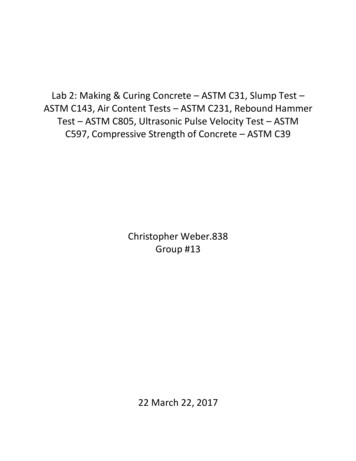
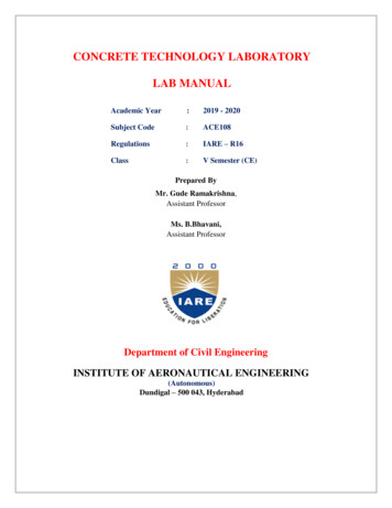
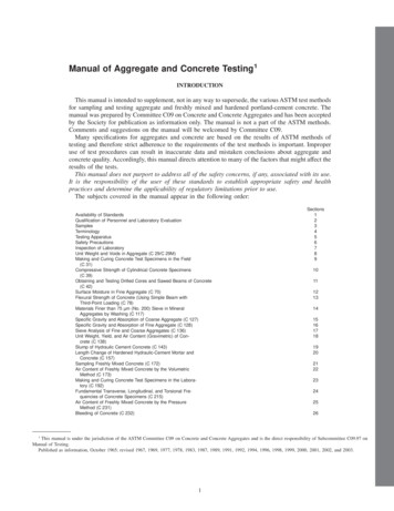
How to design concrete structures using Eurocode 2Figure 1The EurocodesBS EN 1990, Eurocode:Basis of structural designStructural safety,serviceability and durabilityBS EN 1991, Eurocode 1:Actions on structuresActions on structuresBS EN 1992, Eurocode 2: ConcreteBS EN 1993, Eurocode 3: SteelBS EN 1994, Eurocode 4: CompositeBS EN 1995, Eurocode 5: TimberBS EN 1996, Eurocode 6: MasonryBS EN 1999, Eurocode 9: AluminiumBS EN 1997, Eurocode 7:Geotechnical designThis Eurocode underpins all structural design irrespective of thematerial of construction. It establishes principles and requirements forsafety, serviceability and durability of structures. (Note, the correct titleis Eurocode not Eurocode 0.) The Eurocode uses a statistical approachto determine realistic values for actions that occur in combination witheach other.Design and detailingGeotechnicaland seismicdesignBS EN 1998, Eurocode 8:Seismic designEurocode: Basis ofstructural designFigure 2Typical Eurocode layoutThere is no equivalent British Standard for Eurocode: Basis of structuraldesign and the corresponding information has traditionally beenreplicated in each of the material Eurocodes. It also introduces newdefinitions (see Glossary) and symbols (see Tables 2a and 2b), whichwill be used throughout this publication to assist familiarity. Partialfactors for actions are given in this Eurocode, whilst partial factors formaterials are prescribed in their relevant Eurocode.Representative valuesABA: National title pageB: National ForewordC: CEN title pageCDDD: Main textE: Main Annex(es)F: National AnnexDDEFTable 1For each variable action there are four representative values. Theprincipal representative value is the characteristic value and this can bedetermined statistically or, where there is insufficient data, a nominalvalue may be used. The other representative values are combination,frequent and quasi-permanent; these are obtained by applying to thecharacteristic value the factors c 0 , c 1 and c 2 respectively (see Figure 3).A semi-probabilistic method is used to derive the c factors, which varydepending on the type of imposed load (see Table 3). Further informationon derivation of the c factors can be found in Appendix C of the Eurocode.Concrete related Eurocodes and their equivalent current standardsEurocodeTitleSuperseded standardsBS EN 1990Basis of structural designBS 8110: Part 1 – section 2BS EN 1991–1–1Densities, self-weight andimposed loadsBS 6399: Part 1 and BS 648BS EN 1991–1–2Actions on structuresexposed to fire–BS EN 1991–1–3Snow loadsBS 6399: Part 2BS EN 1991–1–4Wind actionsBS 6399: Part 3BS EN 1991–1–5Thermal actions–BS EN 1991–1–6Actions during execution–BS EN 1991–1–7Accidental actions–BS EN 1991–2Traffic loads on bridgesBD 37/88BS EN 1991–3Actions induced by cranesand machinery–BS EN 1991–4Silos and tanks–BS EN 1992–1–1General rules for buildingsBS 8110: Parts 1, 2 and 3BS EN 1992–1–2Fire resistance of concretestructuresBS 8110: Part 1,Table 3.2 andBS 8110: Part 2, section 4BS EN 1992–2BridgesBS 5400: Part 4BS EN 1992–3Liquid-retaining andcontainment structuresBS 8007BS EN 1997–1Geotechnical design –General rulesBS 6031, BS 8002, BS 8004,BS 8006, BS 8008 & BS 8081BS EN 1997–2Geotechnical design – Ground BS 5930investigation and testingBS EN 1998Design of structures for–earthquake resistance (6 parts)2The combination value (c 0 Qk) of an action is intended to takeaccount of the reduced probability of the simultaneous occurrence oftwo or more variable actions. The frequent value ( c 1 Qk) is such that itshould be exceeded only for a short period of time and is usedprimarily for the serviceability limit states (SLS) and also the accidentalultimate limit state (ULS). The quasi-permanent value (c 2 Qk) may beexceeded for a considerable period of time; alternatively it may beconsidered as an average loading over time. It is used for the long-termaffects at the SLS and also accidental and seismic ULS.Combinations of actionsIn the Eurocodes the term ‘combination of actions’ is specifically usedfor the definition of the magnitude of actions to be used when a limitstate is under the influence of different actions. It should not beconfused with ‘load cases’, which are concerned with the arrangementof the variable actions to give the most unfavourable conditions andare given in the material Eurocodes. The following process can be usedto determine the value of actions used for analysis:1. Identify the design situation (e.g. persistent, transient, accidental).2. Identify all realistic actions.3. Determine the partial factors (see below) for each applicablecombination of actions.4. Arrange the actions to produce the most critical conditions.
1. Introduction to EurocodesWhere there is only one variable action (e.g. imposed load) in acombination, the magnitude of the actions can be obtained bymultiplying them by the appropriate partial factors.Where there is more than one variable action in a combination, it isnecessary to identify the leading action (Qk,1) and other accompanyingactions (Qk,i). The accompanying action is always taken as thecombination value.Ultimate limit stateThe ultimate limit states are divided into the following categories:EQU Loss of equilibrium of the structure.STR Internal failure or excessive deformation of the structureor structural member.GEO Failure due to excessive deformation of the ground.FAT Fatigue failure of the structure or structural members.The Eurocode gives different combinations for each of these ultimatelimit states. For the purpose of this publication only the STR ultimatelimit state will be considered.For persistent and transient design situations under the STR limitstate, the Eurocode defines three possible combinations, which are givenin Expressions (6.10), (6.10a) and (6.10b) of the Eurocode (see Tables 4and 5). The designer (for UK buildings) may use either (6.10) or the lessfavourable of (6.10a) and (6.10b).Table 2aSelected symbols for EurocodeSymbolGkDefinitionCharacteristic value of permanent actionQkgGCharacteristic value of single variable actiongQPartial factor for variable actionc0Factor for combination value of a variable actionc1Factor for frequent value of a variable actionc2Factor for quasi-permanent value of a variable actionjCombination factor for permanent actionsPartial factor for permanent actionTable 2bSelected subscriptsSubscriptDefinitionAAccidental situationcConcretedDesignEEffect of actionfiFirekCharacteristicRResistancewShear reinforcementyYield strengthFigure 3Representative values of variable actions ⁵Instantaneous value of QCharacteristic value of QKAt first sight it appears that there is considerably more calculationrequired to determine the appropriate load combination; however, withexperience the designer will be able to determine this by inspection.Expression (6.10) is always equal to or more conservative than the lessfavourable of Expressions (6.10a) and (6.10b). Expression (6.10b) willnormally apply when the permanent actions are not greater than 4.5times the variable actions (except for storage loads (category E, Table 3)where Expression (6.10a) always applies).Combination value of c0 QKFrequent value of c1 QKQuasipermanentvalue of c2 QKTimeTherefore, for a typical concrete frame building, Expression (6.10b) willgive the most structurally economical combination of actions.Table 3Recommended values of c factors for buildings (from UK National Annex)ActionFor members supporting one variable action the combination1.25 Gk 1.5 Qk (derived from (Exp 6.10b))can be used provided the permanent actions are not greaterthan 4.5 times the variable actions (except for storage loads).Serviceability limit stateThere are three combinations of actions that can be used to check theserviceability limit states (see Tables 6 and 7). Eurocode 2 indicateswhich combination should be used for which phenomenon (e.g.deflection is checked using the quasi-permanent combination). Careshould be taken not to confuse the SLS combinations of characteristic,frequent and quasi-permanent, with the representative values thathave the same titles.c0c1c2Imposed loads in buildings (see BS EN 1991–1–1)Category A: domestic, residential areas0.70.50.3Category B: office areas0.70.50.3Category C: congregation areas0.70.70.6Category D: shopping areas0.70.70.6Category E: storage areas1.00.90.8Category F: traffic area, vehicle weight 30 kN0.60.70.7Category G: traffic area, 30 kN vehicle weight 160 kN 0.70.50.3Category H: roofs*000.7Snow loads on buildings (see BS EN 1991–3)For sites located at altitude H 1000 m above sea level0.70.50.2For sites located at altitude H 1000 m above sea levelWind loads on buildings (see BS EN 1991–1–4)0.50.50.20.200Temperature (non-fire) in buildings (see BS EN 1991–1–5) 0.60.50Key*See also 1991–1–1: Clause 3.3.23
How to design concrete structures using Eurocode 2Table 4Design values of actions, ultimate limit state – persistent and transient design situations (table A1.2 (B) Eurocode)Combination Expression referencePermanent actionsLeading variable actionUnfavourableFavourableExp. (6.10)g G, j, sup Gk , j , supg G , j, inf G k , j , infExp. (6.10a)g G, j, sup Gk , j , supg G , j, inf G k , j , infExp. (6.10b)jg G, j, sup Gk , j , supg G , j, inf G k , j , infAccompanying variable actionsMain (if any)g Q,1 Qk,1Othersg Q,1 c 0 ,1 Q k,ig Q,1 c 0 ,1 Qk,1g Q,1 Qk,1g Q,1 c 0 ,1 Q k,ig Q,1 c 0 ,1 Q k,iNote1 Design for either Expression (6.10) or the less favourable of Expressions (6.10a) and (6.10b).Table 5Design values of actions, derived for UK design, ultimate limit state – persistent and transient design situationsCombination Expression referencePermanent actionsUnfavourableLeading variable actionFavourableAccompanying variable actionsMain (if any)OthersCombination of permanent and variable actionsExp. (6.10)1.35 Gk aExp. (6.10a)1.35 Gk aExp. (6.10b)0.925 d1.5c Qk1.0 Gk a1.5 c 0,1b Qk1.0 Gk ax 1.35 Gka1.0 Gka1.5cQkCombination of permanent, variable and accompanying variable actionsExp. (6.10)1.35 Gk a1.0 Gk aExp. (6.10a)1.35 Gk a1.0 Gk aExp. (6.10b)0.925 d x 1.35 Gk a1.0 Gk a1.5 c c 0,i b Q k,i1.5c Qk,11.5 c 0,1b Qk1.5 c c 0,i b Q k,i1.5 c c 0,i b Q k,i1.5c Qk,1Keya Where the variation in permanent action is not considered significant, Gk,j,sup and Gk,j,inf may be taken as Gkc Where the accompanying load is favourable, g Q,i 0b The value of c 0 can be obtained from Table NA A1.1 of the UK National Annex (reproduced here as Table 3)d The value of j in the UK National Annex is 0.925Table 6Design values of actions, serviceability limit statesCombinationPermanent actionsVariable actionsExample of use in Eurocode Gk,j,supGk,j,infQk,1c 0 , i Qk,iFrequentGk,j,supGk,j,infc 1,1 Qk,1c 2 , i Qk,iCracking – prestressed concreteQuasi-permanentGk,j,supGk,j,infc 2,1 Qk,1c 2 , i Qk,iDeflectionNotes1 Where the variation in permanent action is not considered significant. Gk,j,sup and Gk,j,inf may be taken as Gk2 For values of c 0, c 1 and c 2 refer to Table 3Table 7Example design combinations for deflection (quasi-permanent) derived for typical UK reinforced concrete designCombinationPermanent actionsVariable actionUnfavourableLeadingGk a0.3 b Q k,1Shopping areaGka0.6b Q k,1StorageGk a0.8b Q k,1OfficeKeya Where the variation in permanent action is not considered significant Gk,j,sup and Gk,j,inf may be taken as Gk4b Values of c 2 are taken from UK NA (see Table 3)
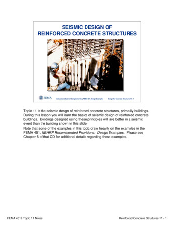
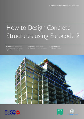
1. Introduction to EurocodesEurocode 1Eurocode 1 supersedes BS 6399: Loading for buildings6 and BS 648:Schedule of weights of building materials7. It contains within its ten parts(see Table 8) all the information required by the designer to assess theindividual actions on a structure. It is generally self-explanatory and itis anticipated the actions to be used in the UK (as advised in the UKNational Annex) will typically be the same as those in the currentBritish Standards. The most notable exception is the bulk density ofreinforced concrete, which has been increased to 25 kN/m3. Currentlynot all the parts of Eurocode 1 and their National Annexes areavailable, in which case it is advised that the loads recommended inthe current British Standards are used.Eurocode 2There are four parts to Eurocode 2; Figure 4 indicates how they fit intothe Eurocode system, which includes other European standards.Table 8Eurocode 1, its parts and dates of publicationReferencePublication dateEurocodeNational AnnexBS EN 1991–1–1Densities,self-weight andimposed loadsJuly2002December2005BS EN 1991–1–2Actions onstructuresexposed to fireNovember2002DueOctober2006aBS EN 1991–1–3Snow loadsJuly2003December2005BS EN 1991–1–4Wind actionsApril2005DueJanuary2007aBS EN 1991–1–5Thermal actionsMarch2004DueDecember2006aBS EN 1991–1–6Actions duringexecutionDecember2005DueJune2007aBS EN 1991–1–7Accidental actionsdue to impactand explosionsSeptember2006DueOctober2007aBS EN 1991–2Traffic loadson bridgesOctober2003DueDecember2006aBS EN 1991–3Actions inducedby cranesand machinerySeptember2006DueJanuary2007aBS EN 1991–4Actions in silosand tanksJune2006DueJune2007aPart 1–1Eurocode 2, Part 1–1: General rules and rules for buildings9 is theprincipal part which is referenced by the three other parts. For the UKdesigner there are a number of differences between Eurocode 2 andBS 8110, which will initially make the new Eurocode seem unfamiliar.The key differences are listed below to assist in the familiarisation process.1. Eurocode 2 is generally laid out to give advice on the basis ofphenomena (e.g. bending, shear etc) rather than by membertypes as in BS 8110 (e.g. beams, slabs, columns etc).2. Design is based on characteristic cylinder strengths not cubestrengths.3. The Eurocode does not provide derived formulae (e.g. for bending,only the details of the stress block are expressed). This is thetraditional European approach, where the application of a Eurocodeis expected to be provided in a textbook or similar publication.The Eurocodes allow for this type of detail to be provided in‘Non-contradictory complementary information’ (NCCI) (SeeGlossary).4. Units for stress are mega pascals, MPa (1 MPa 1 N/mm2).5. Eurocode 2 uses a comma for a decimal point. It is expected thatUK designers will continue to use a decimal point. Therefore toavoid confusion, the comma should not be used for separatingmultiples of a thousand.6. One thousandth is represented by ‰.7. The partial factor for steel reinforcement is 1.15. However, thecharacteristic yield strength of steel that meets the requirementsof BS 4449 will be 500 MPa; so overall the effect is negligible.8. Eurocode 2 is applicable for ribbed reinforcement with characteristicyield strengths of 400 to 600 MPa. There is no guidance on plainbar or mild steel reinforcement in the Eurocode, but guidance isgiven in the background paper to the UK National Annex10.9. The effects of geometric imperfection (‘notional horizontal loads’)are considered in addition to lateral loads.TitleKeya Planned publication date (correct at time of publication) Source: BSI8Figure 4Relationship between Eurocode 2 and other EurocodesBS EN 1997EUROCODE 7GeotechnicaldesignBS EN 1990EUROCODEBasis of structuraldesignBS EN 1998EUROCODE 8SeismicdesignBS EN 206SpecifyingconcreteBS EN 1991EUROCODE 1Actions onstructuresBS EN 10080ReinforcingsteelsBS 8500SpecifyingconcreteBS EN 1992EUROCODE 2Design of concretestructuresBS 4449ReinforcingsteelsPart 1–1: Generalrules for structuresBS EN 13670Execution ofstructuresPart 1–2: Structuralfire designBS EN 13369PrecastconcreteBS EN 1992EUROCODE 2Part 2:BridgesBS EN 1992 Part 3:EUROCODE tandards5
How to design concrete structures using Eurocode 210. Minimum concrete cover is related to bond strength, durabilityand fire resistance. In addition to the minimum cover anallowance for deviations due to variations in execution(construction) should be included. Eurocode 2 recommendsthat, for concrete cast against formwork, this is taken as 10 mm,unless the construction is subject to a quality assurance systemin which case it could be reduced to 5 mm or even 0 mm wherenon-conforming members are rejected (e.g. in a precast yard).It is recommended that the nominal cover is stated on thedrawings and construction tolerances are given in thespecification.11. Higher strengths of concrete are covered by Eurocode 2, up toclass C90/105. However, because the characteristics of higherstrength concrete are different, some Expressions in the Eurocodeare adjusted for classes above C50/60.12. The ‘variable strut inclination’ method is used in Eurocode 2 forthe assessment of the shear capacity of a section. In practice,design values for actual structures can be compared withtabulated values. Further advice can be found in Chapter 4,originally published as Beams11.13. The punching shear checks are carried out at 2d from the face ofthe column and for a rectangular column, the perimeter isrounded at the corners.14. Serviceability checks can still be carried out using ‘deemed tosatisfy’ span to effective depth rules similar to BS 8110. However,if a more detailed check is required, Eurocode 2 guidance variesfrom the rules in BS 8110 Part 2.15. The rules for determining the anchorage and lap lengths are morecomplex than the simple tables in BS 8110. Eurocode 2 considersthe effects of, amongst other things, the position of bars duringconcreting, the shape of the bar and cover.Part 1–2Eurocode 2, Part 1–2: Structural fire design12, gives guidance on design forfire resistance of concrete structures. Although much of the Eurocodeis devoted to fire engineering methods, the design for fire resistancemay still be carried out by referring to tables for minimum cover anddimensions for various elements. These are given in section 5 of Part1–2. Further advice on using the tabular method is given in Chapter 2,originally published as Getting started 13.Eurocode 7Eurocode 7: Geotechnical design17 is in two parts and gives guidance ongeotechnical design, ground investigation and testing. It has a broadscope and includes the geotechnical design of spread foundations, piledfoundations, retaining walls, deep basements and embankments. Likeall the Eurocodes it is based on limit state design principles, which isa significant variation for most geotechnical design. Further guidancerelated to simple foundations is given in Chapter 6, originallyppublished as Foundations18.Eurocode 8Eurocode 8: Design of structures for earthquake resistance19 is divided intosix parts and gives guidance on all aspects of design for earthquakeresistance and covers guidance for the various structural materials forall types of structures. It also includes guidance for strengthening andrepair of buildings. In areas of low seismicity it is anticipated that detailingstructures to Eurocode 2 will ensure compliance with Eurocode 8.Related StandardsBS 8500/BS EN 206BS 8500: Concrete – Complementary British Standard to BS EN 206–120replaced BS 5328 in December 2003 and designers should currentlybe using this to specify concrete. Further guidance can found inChapter 11, originally published as How to use BS 8500 with BS 811021.BS 4449/BS EN 10080BS 4449: Specification for carbon steel bars for the reinforcement ofconcrete22 has been revised ready for implementation in January 2006.It is a complementary standard to BS EN 10080 Steel for thereinforcement of concrete23 and Normative Annex C of Eurocode 2. Themost significant changes are that steel characteristic yield will changeto 500 MPa. There are three classes of reinforcement, A, B and C, whichindicate increasing ductility. Class A is not suitable for use whereredistribution of 20% and above has been assumed in the design.BS EN 13670Part 2Eurocode 2, Part 2: Bridges14 applies the general rules given in Part 1–1to the design of concrete bridges. As a consequence both Part 1–1 andPart 2 will be required to carry out a design of a reinforced concretebridge.Part 3Eurocode 2, Part 3: Liquid-retaining and containment structures15 appliesthe general rules given in Part 1–1 to the liquid-retaining structuresand supersedes BS 800716.6BS 8110 Part 1 sections 6 and 7 specify the workmanship for concreteconstruction. There is no equivalent guidance in Eurocode 2, and it isintended that execution (construction) will be covered in a newstandard BS EN 13670 Execution of concrete structures24. This is still inpreparation and is not expected to be ready for publication until 2008at the earliest. In the intervening period the draft background paper tothe UK National Annex of Eurocode 2, Part 1-110 recommends thatdesigners use the National structural concrete specification for buildingconstruction25, which refers to BS 8110 for workmanship.
1. Introduction to EurocodesGlossary of Eurocode terminologyTermDefinitionPrinciplesClauses that are general statements, definitions, requirements and analytical models for which noalternative is permitted. They are identified by (P) after the clause number.Application RulesThese are generally recognised rules, which comply with the principles and satisfy their requirements.Nationally Determined Parameter (NDP)Eurocodes may be used to satisfy national Building Regulations, which themselves will not beharmonized. NDPs are therefore used to allow a country to set its own levels of safety. NDPs also allowcertain other parameters (generally influenced by climate, geography and geology) to be left open forselection nationally: NDPs are advised in the National Annex.National Annex (NA)A National Annex accompanies each Eurocode and it contains a) the values of NDPs b) the nationaldecision regarding the use of Informative Annexes and c) references to NCCIsNormativeThe term used for the text of Standards that forms the core requirements. Compliance with Eurocodeswill generally be judged against the normative requirements.InformativeA term used only in relation to annexes, which seek to inform rather than require.NCCINon-contradictory complementary information. References in a National Annex which contains furtherinformation or guidance which does not contradict the Eurocode.Characteristic valueA value that may be derived statistically with a probability of not being exceeded during a referenceperiod. The value corresponds to a specified fractile for a particular property of material or product. Thecharacteristic values are denoted by subscript ‘k’ (e.g. Qk etc). It is the principal representative valuefrom which other representative values may be derived.Representative valueValue used for verification of a limit state. It may be the characteristic value or an accompanying value,e.g. combination, frequent or quasi-permanent.Design valuesThese refer to representative values modified by partial factors. They are denoted by subscript ‘d’(e.g. f cd f ck /g c ; Qd g Q Qk).Action (F)Set of forces, deformations or accelerations acting on the structure.Combination of actionsSet of design values used for the verification of the structural reliability for a limit state under thesimultaneous influence of different and statistically independent actions.Fixed actionAction that has a fixed dis
Geotechnical design BS EN 1998,Eurocode 8: Seismic design D D D D C B A Eurocode: Basis of structural design This Eurocode underpins all structural design irrespective of the material of construction. It establishes principles and requirements for safety, serviceability and durability of