Transcription
GEN III - VVTVOTE BASED AUTO CHANGEOVER VAVwith WIRELESS PROGRAMMABLE THERMOSTATSAM O D U L A T I N GS Y S T E M70 72 75 68 INSTALLATION AND APPLICATIONS MANUAL
TABLE OF CONTENTS1 OVERVIEWSystem OperationComponent SelectionSequence Of OperationSystem Schematic Overview33456COMPONENTS2 SYSTEMGEN III Controller7310Communicating Damper BoardWireless ThermostatINSTALLATION INSTRUCTIONSGEN III ControllerDamper 1 InstallationThermostat Installation / Battery Replacement789101213AND START UP4 COMMISSIONINGSync Dampers To Wireless Zone Thermostats14SYSTEM OPERATION5 CONFIRMConfirm Cool Call And Damper Operation18OVERVIEW AND OPERATION6 THERMOSTATSet Thermostat Display Modes22DAMPERS7 ZONERound And Rectangular Sizing And Selection37DAMPERS8 BYPASSSlaving Bypass Dampers419 TROUBLESHOOTING45Sync Monitor Thermostat To GEN III ControllerConfirm CommunicationsSet Unit TypeSet ClockSet High / Low LimitsSet Fan OperationConfirm Heat Call And Damper OperationAuxiliary Heat / Reheat / W1 First OperationSupplemental Heat – Wiring OptionsThermostat Operation – End User GuideZone Set Up MenuMonitor Thermostat ConfigurationSet SchedulesLock Thermostats, Master Temperature SetSystem Diagnostic, High / Low LimitSecond Stage Delay, Override Hours, Priority VoteFan Mode, Unit Type, Sync Monitor, Maverick CallSystem Air Balance, Temp Format, Clock, PasswordNumber Of Dampers, LAT Calibration, Morning Warm UpManufacturer’s DefaultWireless Remote SensorSlaving Zone DampersIPC – Static Pressure Controller10 SYSTEM SET UP DIRECTORY11 FINAL SYSTEM 34353740424348492
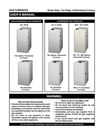
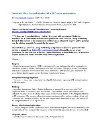
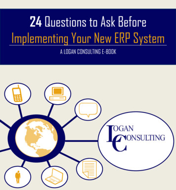
GEN III – VVTSYSTEM OVERVIEWSYSTEM OVERVIEWGEN III – VVT is a commercial modulating zone control system controlling 2-20 independent zones per unitutilizing wireless Zonex thermostats. The GEN III controller is designed for Auto Changeover, multi-stage HeatPump (2C/3H) or Gas Electric (2C/2H) applications.Sophisticated, integrated software in the wireless thermostat allows for a wide range of system control andchangeover strategies, allowing the contractor to tailor the GEN III system to a specific application.Additional features include LED status indication of all system functions, digital leaving air temperature, returnair temperature and outside air temperature display, fully adjustable capacity control with on-board limitsettings and optional staging strategies. An integrated clock allows for setup and night setback scheduling,globally or individually available for each wireless thermostat, with selectable 2 to 8 hour override, along witha unique feature to remotely lock each thermostat independently in the system.The system provides the installing contractor with a simple startup diagnostic to minimize wiring errors andspeed installation.GEN III is recognized as the Industry's easiest zone control system to install and wire. The GEN III Systemoperates over an unshielded-two-wire data link, along with two 24 VAC power wires all daisy chained fromdamper to damper with no home run wiring required. Wireless thermostats do not require hardwire power orwiring between the thermostats and dampers. Each Wireless thermostat is synced with its correspondingmodulating damper providing effective temperature control throughout the system.24VAC / 40VATRANSFORMERLEAVINGAIR SENSORSTATICPRESSURESENSOR1ZONEDAMPERBYPASS DAMPER24TR VACAN/SFO LDRAWING ONLYUP TO 20 DAMPERSPULL 24V POWER AND UNSHIELDED TWISTED PAIRDAISY CHAINED FROM DAMPER TO DAMPERRefer to Systemcontroller section forwiring information.3
GENIII-VVTSYSTEM COMPONENTSwith Wireless ThermostatsCOMPONENT SELECTION OVERVIEWGEN III ControllerPart # - GEN III1 - Per RTU or Split SystemSupports 2 - 20 Fully Modulating ZonesDaisy Chain: Belden 8740 Communications wire and 24VAC from Damper to Damper1-24VAC / 40VA Transformer Powers the GEN III and All the Dampers in the SystemGEN III Wireless ThermostatPart # - WSTAT1 - Thermostat per DamperModulating Zone DampersPart #WST Damper Size - Round Damper (up to 1.75 S.P.)WCD Damper Size - Rectangular Dampers (up to 1.75 S.P.)Slave up to 3 Zone Dampers per StatUse STMPD or STCD Damper for SlavesElectronic Bypass Damper(Includes Integrated Static Pressure Control)Part #STBP Damper Size - Round Bypass DampersSTCDBP Damper Size - Rectangular Bypass Dampers1-24 VAC / 40VA Transformer to Power Bypass DamperFor assistance, contact Zonex at (800) 288-2966or visit zonexproducts.com for more information4
GEN III– VVTSEQUENCE OF OPERATIONVote Based Auto Changeover Bypass VAV with Programmable Wireless ThermostatsGEN III controller wires to the HVAC unit with legacy style connections Y1, Y2, W1, W2, OB, G, R. Once everyminute the controller communicates to each damper via RS485 connection daisy chained along with 24 V of powerwired damper to damper. Each damper is equipped with a damper board ID and synced to its wirelessprogrammable thermostat, installed within 100 feet of the communicating damper board in the system.The GEN III is an auto changeover, vote based VVT system. As thermostats call for heating or cooling, votes aretallied at the GEN III controller; and, based on the majority of votes received, the HVAC unit operates in the modeof majority votes. If majority changes, the system controller will automatically initiate a changeover sequence withbuilt in time delays to protect the equipment before changing over to the new mode of operation.When the last calling zone is satisfied in either heat or cool mode, the GEN III controller will terminate the HVACoutputs after the next “poll”; and the blower output will be de-energized (unless controller is configured forconstant fan) after a 4-minute purge cycle. During the purge cycle no heat or cool calls are recognized.The wireless zone thermostats control and modulate the zone dampers based on variance from set point to aposition that will match the supply load to the demand requirement. When the HVAC unit is running, if a zonethermostat is not calling or is calling for the opposite mode, its corresponding damper fully closes. When theHVAC unit is not running, the thermostats open to the Vent mode to provide ventilation, if the indoor blower fan isrunning continuously.While the HVAC unit is running, the capacity control LAT device monitors the leaving air temperature from theHVAC unit and will cycle the HVAC unit to maintain the air temperature with a preset range to eliminate coilfreeze-up and premature heat exchanger failure. When the system is in the heating mode and a majority votechanges to cooling, a changeover timer begins and will run heating for 5 minutes or until heat call is satisfied andthen cycle into a changeover purge. After a 4-minute purge cycle, Cooling is turned on until the cool call is satisfiedor there is a majority vote for heat received by the GEN III controller. If all calls have been satisfied, after the 4minute off delay, dampers will modulate to approximately 40% open position for ventilation mode.The system fan/blower operation can be configured for ON or intermittent AUTO operation. The controllers areshipped from the factory for Auto fan operation. The only time the fan will run is when there is a call from thecontroller for heating or cooling. If the system is configured for fan ON operation, the fan will run continuouslyduring occupied time and intermittently during unoccupied time.All zone thermostats are synced or paired with its respective modulating zone damper, which is equipped withantenna and communicating damper board. One zone thermostat in the system shall be enabled as the Monitorthermostat and synced with the GEN III controller to interact and initiate control decisions for the system. TheMonitor shall establish global or individual schedules for the system, lock thermostats individually and provideminimal local adjustment, establish master temperature settings individually or globally for the system, andprovide diagnostic functions to streamline system troubleshooting. Air balance shortcuts, along with passwordprotection, are also enabled at the Monitor thermostat. Sleep and energy saving modes are available to extendbattery life and enhance operation.Voting demand strategy can be enhanced by adding Priority votes or by giving a NULL vote to individualthermostats in the system, thereby weighting certain zones more than others. Priority votes allow you to select 0, 1,2, or 3 additional votes for a thermostat that has unusual loads, like a conference room. A change to 0 for priority inthat zone stat configuration will create a NULL vote for HEAT/COOL and will not allow the stat to place a call for heator cool, but will allow damper operation based on system mode of operation, HEAT/COOL/VENT.The GEN III provides effective temperature control and minimizes wiring issues by using wireless programmablezone thermostats. No computer or software tools are required for installation, commissioning or servicing thesystem.5
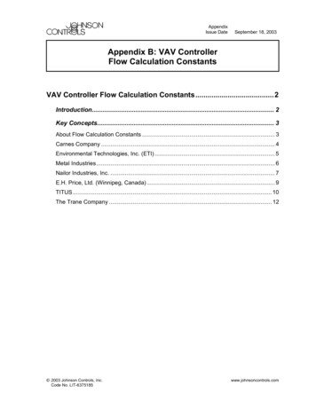
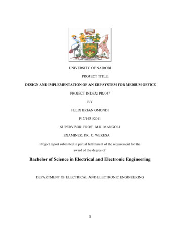
GEN III-VVTVOTE BASED AUTO CHANGEOVER VAVWITH WIRELESS THERMOSTATSPOWER SWITCH24VAC INPower CommunicationC TR1TX BR TR2RX ASTATUS LIGHTSID / SYNCGEN III-VVT24VAC OUTTerminal ConnectionsC1AUX SENSOR (AS)LEAVING AIR SENSOR (LVAIR)TO UNIT TERMINALSOUTSIDE AIR SENSOR (OA)RETURN AIR SENSOR MCRORCCAUXABMODULATING DAMPERDM-3DM-2TR1TR2TR1BABMODULATING DAMPERDM-1AUXAABMODULATING MCMCRORCRS485 COMMUNICATION LINK ( BELDEN 8740)MODULATING DAMPERDM-4DAISY CHAIN 24VAC ANDDATALINK CABLE (BELDEN 8740)TO ALL ZONE DAMPER BOARDS EXPANDABLE TO 20 ZONESDEVICEIDCONTROL BOARDC1THERMOSTATDESCRIPTIONGEN III CONTROLLERCONTROLS 2-20 ZONE DAMPERS ONLY 1 24VAC 40VA TRANSFORMERPOWERS ALL SUPPLY DAMPERST1 -T20 ZONEX WIRELESS THERMOSTATREMOTE SENSORRSZONEX WIRELESS REMOTE SENSORZONE DAMPER MOTORDMSUPPLIED WITH ZONE DAMPER (FACTORY PRE-WIRED)SYSTEM TRANSFORMERTR124VAC/40VA TRANSFORMER SIZED @ (2VA PER ZONE DAMPER)DAISY CHAIN DAMPER TO DAMPERBYPASS TRANSFORMERTR2IND. 24VAC/40VA TRANSFORMER TO POWER THE BYPASS DAMPERSUPPLY / RETURN AIRLAT DISCHARGE SENSORSLATSUPPLY LAT LOCATED BEFORE THE BYPASS. RETURN LATLOCATED AFTER THE BYPASSINTEGRATEDSTATIC PRESSURE CONTROLIPCSUPPLIED WITH THE ZONEX BYPASS DAMPER (FACTORY PRE-WIRED)STATIC PRESSURE TUBESPTLOCATED AFTER THE BYPASS BEFORE THE FIRST SUPPLY TAKEOFFBYPASS DAMPER MOTORBP-DMSUPPLIED WITH ZONEX BYPASS DAMPER (FACTORY PRE-WIRED)WIRELESS COMMUNICATIONCOMMUNICATES WITH WIRELESS DAMPER BOARD AND THERMOSTATRS485 COMMUNICATION LINKTWISTED PAIR WIRING -BELDEN 8740 DAISY CHAIN DAMPER TO DAMPERVISIT OUR ON-LINE CATALOG AT ZONEXPRODUCTS.COMFOR APPLICATIONS ASSISTANCE CALL 800-228-29666
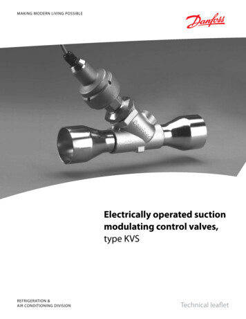
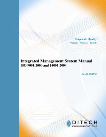
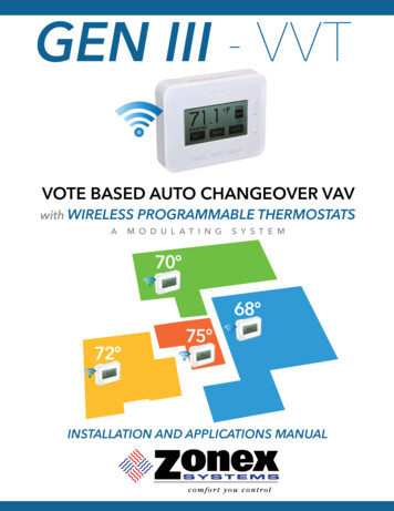
GEN III– VVTSYSTEM COMPONENTSGEN III CONTROLLERController hange-over Universal Gas/Electric or Heat Pumpsystem controller (Part #GEN III ). The GEN III controls azoned 2H/2C Gas/Electric HVAC unit or 3H/2C zonedHeat Pump unit and communicates with and supports upto 20 zones, utilizing pressure dependent, modulatingdampers and wireless thermostats. The GEN III gathersinformation every 60 seconds from each damper boardwhile the wireless thermostats communicate with the system over a two-wire data link directing control baseddecisions to the HVAC equipment. The GEN III is powered with one 24 V 40VA transformer, which alsopowers all dampers in the system.Power from the controller, along with a two-wire twisted paircommunications loop, is daisy chained damper to damper to streamline installation and systemcommunications. The GEN III is equipped with integrated capacity control and High and Low temperaturelimits to protect the compressor and heat exchanger. Outside air and return air sensors are also provided.The HVAC unit is staged based on leaving air temperature and time. Auto change-over operation is votebased, predicated on a first call, first served majority wins on changeover algorithm. Additional controlstrategies are established on a Monitor Thermostat which initiates control decisions with the GEN III systemcontroller. Review controller terminal connections on the exhibit below:APOWER SWITCHDEFBCID / SYNCSTATUS LIGHTS24VAC IN24VAC OUTTO UNIT TERMINALSAUX SENSOR (AS)LEAVING AIR SENSOR (LVAIR)IOUTSIDE AIR SENSOR (OA)JRETURN AIR SENSOR (RA)GHKCOMMUNICATION LINK (BELDEN 8740)A. On/Off SwitchB. ID/Sync Button and Communication link lightC. Unit Status LightsD. 24vac IN to power the GEN III boardE. 24vac OUT daisy chained out to the damper boardsF. Unit TerminalsG. RX/TX communication link (Belden 8740)H. Aux Sensor (AS)I. Leaving Air Sensor (LVAIR)J. Outside Air Sensor (OA)K. Return Air Sensor (RA)7
GEN III– VVTCOMMUNICATING DAMPER BOARDA damper board resides on each zone damper to carry power and communications information from thedamper to the GEN III controller. The damper control board has four LED lights providing damper andsystem information.The BLUE LED (R) confirms communications and to sync the damper with its associated thermostat.The RED LED (U) is illuminated when the damper is modulating to the closed position.The GREEN LED (T) is illuminated when the damper is modulating to the open position.The YELLOW LED (S) is illuminated when AUX heating is calling.Once all dampers and the GEN III controller are wired into the system and the GEN III controller is turnedON, the BLUE light will flash 4 times when communicating with the GEN III controller, and 2 times when thedamper control board communicates with the wireless thermostat.The damper control board can be removed by slipping the mount away from the damper hat section,simplifying wiring from the GEN III controller and AUX heat if utilized.Each damper control board must be synced with its respective thermostat. Once the damper is energizedand associated thermostat has its ID set, press the ID button on the damper control board until blue lightflashes continuously and then press the YES button on the wirele
The GEN III is an auto changeover, vote based VVT system. As thermostats call for heating or cooling, votes are tallied at the GEN III controller; and, based on the majority of votes received, the HVAC unit operates in the mode of majority votes. If majority changes, the system controller will automatically initiate a changeover sequence with