Transcription
Deployment GuideWeb FilterDeployment GuideA Step-by-Step Technical Guide
Deployment GuideNotice:The information in this publication is subject to change without notice.THIS PUBLICATION IS PROVIDED “AS IS” WITHOUT WARRANTIES OF ANY KIND, EXPRESS ORIMPLIED, INCLUDING ANY WARRANTIES OF MERCHANTABILITY, FITNESS FOR A PARTICULARPURPOSE OR NONINFRINGEMENT. CITRIX SYSTEMS, INC. (“CITRIX”), SHALL NOT BE LIABLE FORTECHNICAL OR EDITORIAL ERRORS OR OMISSIONS CONTAINED HEREIN, NOR FOR DIRECT,INCIDENTAL, CONSEQUENTIAL OR ANY OTHER DAMAGES RESULTING FROM THE FURNISHING,PERFORMANCE, OR USE OF THIS PUBLICATION, EVEN IF CITRIX HAS BEEN ADVISED OF THEPOSSIBILITY OF SUCH DAMAGES IN ADVANCE.This publication contains information protected by copyright. Except for internal distribution, no partof this publication may be photocopied or reproduced in any form without prior written consent fromCitrix.The exclusive warranty for Citrix products, if any, is stated in the product documentation accompanyingsuch products. Citrix does not warrant products other than its own.Product names mentioned herein may be trademarks and/or registered trademarks of their respectivecompanies.Copyright 2008 Citrix Systems, Inc., 851 West Cypress Creek Road, Ft. Lauderdale, Florida 333092009 U.S.A. All rights reserved.
Table of ContentsIntroduction.4Solution Requirements.5Prerequisites.5Network Diagram.6First time connectivity.8Serial Connection.8Ethernet Connection.8NetScaler Configuration.9Deployment Model: Netscaler Two-Arm Mode, Server Load Balancing, RNAT.9Licensing.10Basic Features.11IP Addresses, Interfaces and VLANs.12RNAT Configuration.15About RNAT.15Load Balancing Configuration.16About Server Load Balancing.16Create Server Objects.16Create Service Groups.17Create LB Virtual Server Objects (VIPs).18Load Balancing Methods & Persistence.19St.Bernard Web Filter.20Outbound Web Filter.20Outbound Web Filter for XenApp.24Appendix A - NetScaler Application Switch Configuration.26Headquarters NetScaler.26
IntroductionCitrix NetScaler optimizes the delivery of web applications — increasing security and improvingperformance and Web server capacity. This approach ensures the best total cost of ownership(TCO), security, availability, and performance for Web applications. The Citrix NetScaler solution is acomprehensive network system that combines high-speed load balancing and content switching withstate-of-the-art application acceleration, layer 4-7 traffic management, data compression, dynamiccontent caching, SSL acceleration, network optimization, and robust application security into a single,tightly integrated solution.Citrix XenApp , a member of the Citrix Delivery Center product family, is an end-to-end Windowsapplication delivery system that offers both client-side and server-side application virtualization, foroptimal application performance and flexible delivery options.St. Bernard products are used in enterprises of all sizes across most commercial markets includinghealthcare, manufacturing, finance, insurance, real estate, and public administration, as well aseducational institutions and state/local governments.St. Bernard offers a full suite of secure content management solutions that integrate on-premise applianceswith on-demand services to protect corporate networks from online threats, manage bandwidth use andenforce acceptable use policies. This industry-leading hybrid solution platform offers the security andcontrol of an on-premises appliance with the scalability of an on-demand service.St. Bernard is the first and only company to support a true Hybrid Product Line, combining the securityand control of h-Series appliances with the unlimited scalability of iPrism Managed Services. Hybridsolutions provide only the best functions from both an appliance and managed services approachto deliver filtering solutions at the best location within the IT infrastructure to maximize efficiency andvalue.The Award-winning iPrism Web Filter secures organizations from Internet-based threats such as malware,spyware, IM, P2P, and inappropriate content, at the perimeter, while it helps enforce acceptable use andsecurity policies. The new iPrism h-Series appliances also offer unmatched power, value and performance.With dual quad-core processors and hot-swappable SATA hard drives and power supplies, there isn’t anappliance on the market that equals the new iPrism h-Series.When integrated with Citrix NetScaler and Application Firewall, the St.Bernard offers the extra level ofprotection that organizations are often looking for to filter outbound traffic.When integrated with Citrix XenApp, the St.Bernard provides an added layer of security by filteringindividual client sessions that connect to the internet from the Application Virtualization platform XenApp.This deployment guide was created as the result of validation testing with The Citrix NetScaler, ApplicationFirewall, Citrix XenApp and St.Bernard iPrism h-Series Web Filter. This deployment guide walks throughthe step-by-step configuration details of how to configure the Citrix NetScaler application switch, andthe St.Bernard iPrism Web Filter.
Solution Requirements Application Switch - Citrix NetScaler NAT (Reverse NAT) Application Firewall - Citrix Application Firewall Application Virtualization - Citrix XenApp Web Filter - St.Bernard iPrism Web Filter, IM/P2P, AntivirusPrerequisites Citrix NetScaler L4/7 Application Switch, running version 8.0 (Quantity x 2 for Headquarters &Remote sites). Citrix Application Firewall Citrix XenApp (Citrix Presentation Server) St.Bernard iPrism h-Series Web Filter Client laptop/workstation running Internet Explorer 6.0 , Ethernet port 9-pin serial cable -or- USB-to-serial cable
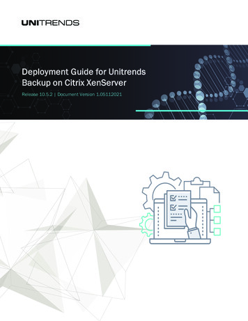
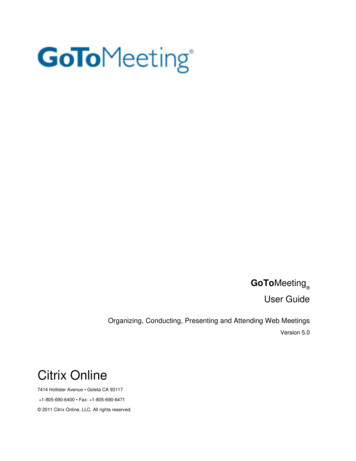
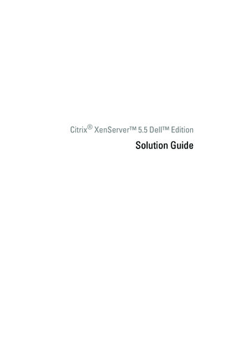
Network DiagramThe following is the Network that was used to develop this deployment guide, and is representative of a solution implemented at a customer site.Shown here with NetScaler in two-arm mode and St.Bernard in one-arm mode along with Citrix XenApp.VLAN LegendVLAN 172VLAN 65NetScalerVLAN 1: (Mgmt)Interface 1/2, UntaggedNSIP: 169.145.91.71 / 24SNIP: 169.145.91.1 / 24VLAN 65:Interface 1/8, UntaggedSNIP: 65.89.216.1 / 24VIP: 65.89.216.151 / 24VLAN 172:Interface 1/7, UntaggedSNIP: 172.16.104.1 / 24 St.Bernard Web FilterMgmt IP:172.16.104.111 / 24Gateway:172.16.104.1XenAppIP Address:172.16.104.151 / 24Gateway:172.16.104.1
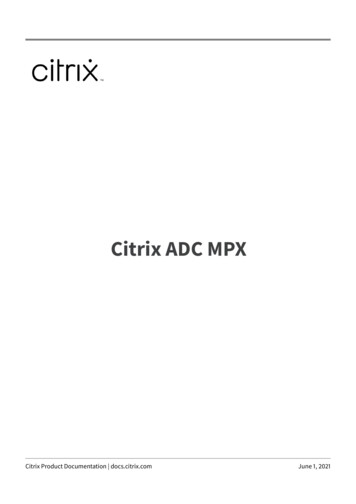
Application ServerDFG65.89.216.1NAT65.89.216.2LB VIP65.89.216.151Citrix NetScaler St.Bernard Mgmt int 1/2Web tside67.97.253.0/24vlan 65Inside172.16.104.0/24vlan 172MacWindowsXenAppThin ClientsCitrix XenApp
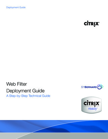
Serial: 9600, n, 8, 1 Default IP Address:192.168.100.1First time connectivitySerial ConnectionEthernet ConnectionThe NetScaler can be accessed by the serial port through anyterminal emulation program. Windows Hyperterm is commonlyused on a laptop or workstation. Connect a 9-pin Null Modemcable (or USB-to-9-pin cable) from the computer to the NetScaler’sconsole port. In the terminal emulation program configure thesettings for 9600 baud, No stop bits, 8 data bits, and 1 parity bit.The login prompt should appear. The default login is nsroot, nsroot.It is advisable to change the nsroot password once connected.The NetScaler can also be accessed by the default IP Addressof 192.168.100.1, either through an http, https, telnet or sshconnection. Once connected, the login prompt should appear.The default login is nsroot, nsroot. It is advisable to change thensroot password once connected.Once connected type in the CLI command ‘configns’ (‘nsconfig’ ifat the shell prompt). Select option 1 to change the NetScaler IPAddress and Network Mask. Exit, save and reboot. Type in the CLI command ‘configns’ (‘nsconfig’ if at the shellprompt). Select option 1 to change the NetScaler IP Address andNetwork Mask. Exit, save and reboot.Note: Changing the NetScaler IP Address always requires areboot.
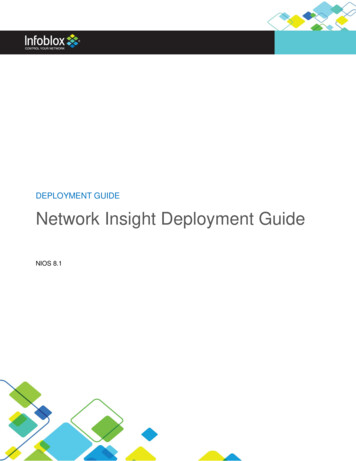
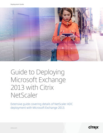
NetScaler ConfigurationDeployment Model: Netscaler Two-Arm Mode, Server Load Balancing,RNAT.The NetScaler in this example will be used in two-arm mode. The NetScaler in Two-Arm mode usesdifferent interfaces for the segmentation of VLAN traffic, providing an additional physical layer ofseparation. This deployment can easily have been implemented using a Trunk port on the Netscaler andLayer 2 switch. For incoming connections to the Application server, we will configure a Load BalancingVIP on the Internet facing subnet.Connect to the NetScalervia the NSIP using a webbrowser.In this example:NS1: http://10.217.104.71EthernetNote: Java will be installed.Default login is: nsroot,nsroot.
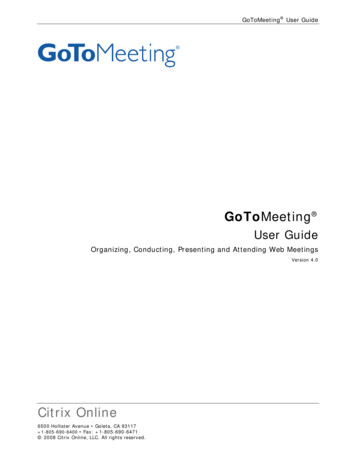
LicensingThe availability of a feature is controlled by a license key. When using the system for the first time, youneed to load the license key and then enable the feature.To add new licenses.From the GUI, navigateto NetScaler System Licenses ManageLicenses.Note:Licenses are tied to the hostname of the switch and must match. The hostname can be found underNetScaler System. Make sure the license file is in the correct location. With release 8.0 all licensefiles must be in the /nsconfig/license directory in order to be recognized.Also, check the “hosts” files in /nsconfig and in /etc, and make sure both include lines for localhostand for the NetScaler hostname as defined in the configuration and /nsconfig/rc.conf.A properly configured hosts file should look similar to the following (using nshost as the examplehostname defined for this NetScaler).127.0.0.1127.0.0.110localhostnshost
Basic FeaturesLoad Balancing is enabled in Basic Features.From the GUI, navigate toNetScaler System Settings Basic Features.Select Load Balancing andclick OK.11
Important NetScaler IP AddressesAcronymDescriptionUsageNote: NSIP is Mandatory and requires a reboot.NSIPNetScaler IP AddressThe NetScaler IP (NSIP) is the management IP address for theappliance, and is used for all management related access to theappliance. There can only be one NSIP.SNIPSubnet IP AddressThe Subnet IP address (SNIP) allows the user to accessan Application Switch from an external host that is residingon another subnet. When a subnet IP address is added, acorresponding route entry is made in the route table. TheApplication Switch uses the SNIP as the source IP Address foroutgoing packets, when the “USNIP” mode is enabled. USNIPis enabled by default. (With USNIP enabled, configuration ofMIP is unnecessary). The SNIP can also be used as the TaggedVLAN IP, and for RNAT.MIPMapped IP AddressThe mapped IP address (MIP) is becoming outdated. It hastraditionally been used by the Application Switch to representthe client when communicating with the backend managedserver. Mapped IP addresses (MIP) were used for server-sideconnections and can be used for Reverse NAT. Think of this asthe client’s source address on the server-side of the ApplicationSwitch, assuming a two-arm proxy deployment. When usingthe USNIP mode above, MIP’s are unnecessary.VIPVirtual IP AddressThe Virtual Server IP address (VIP) is used by the ApplicationSwitch to represent the public facing ip address of the managedservices. ARP and ICMP attributes on this IP address allowusers to host the same vserver on multiple Application Switchesresiding on the same broadcast domain.DFGDefault GatewayIP Address of the router that forwards traffic outside of thesubnet where the appliance is installed.Note:USNIP mode is enabled by default. If both USIP mode and USNIP mode are enabled, USIP modetakes precedence over USNIP mode.IP Addresses, Interfaces and VLANsAssigning IP Addresses to Interfaces is done ‘virtually’ through the use of port based VLANs.By default, all the interfaces on the system are in a single port-based VLAN as untagged interfaces.This VLAN is the default VLAN with a VID equal to 1.When an interface is added to a new VLAN as an untagged member, the interface is automaticallyremoved from the default VLAN and placed in the new VLAN. This becomes a convenient feature,such that when we plug the Netscaler into a Switch that is using VLANs with tagging, we only need tocheck the box, to turn on tagging. VLANs are typically used to separate subnet traffic.If Trunking is turned On, you will see an interface as a member of more than one VLAN.12
Add the remaining IP AddressesIP Addresses (SNIPs) that are used for routing between VLANs and RNAT are added separately accordingto the table in the network diagram. Note that VIP addresses are created later during Load Balancingconfiguration, not at this time. The following screen shots are for the NetScaler.Add the remainingAddresses.IPNetScaler Network IPs Add.Note: Dynamic Routingmust be enabled on theSubnet IP (SNIP) for theseroutes to be propagated inrouting protocols.Make sure you take thisopportunity to “Save” theconfiguration on both thePrimary and SecondaryNetScalers.13
Create VLANs and AssignSubnet IP Addresses tothem.NetScaler Network VLANs Add.Note: For this example: We createVLANs 65 & 172. We assignVLAN 65 to Interface 1/8and VLAN 172 to interface1/7.(We did not use VLANTrunking in this deployment,but easily could have byturning on trunking on oneof the NetScaler interfaces,and assigning VLANs 65 &172 to it).Interface1/2isourmanagement interface, inVLAN 1.NetScaler Network VLANs, to add VLAN andInterface assignments onthe Application Switch. Besure to bind the ip addressto each VLAN, and enabledynamic routing.Note: Dynamic Routingmust be enabled on theVLAN for these routes tobe propagated to routingprotocols.14
RNAT ConfigurationAbout RNATThe NetScaler system supports Reverse Network Address Translation (RNAT) or NAT for outboundconnections. When the system performs RNAT, it replaces the source IP addresses of packets generatedby the back-end servers with a NAT IP address. The NAT IP address is a public IP address. By default,the NAT IP address is a MIP. However, you can configure the system to use a Subnet IP address as theNAT IP addresses, which we do in this deployment guide.From the GUI, navigate toNetScaler Network Routing Configure RNAT Create.With this configurationall internal private ipaddresses that originate inthe 10.217.104.0 networkwill be translated (NAT’d) to65.89.216.2 as they reachthe public internet.We added a separate SNIP65.89.216.2 to be used forthe public NAT address, butcould have also used the65.89.216.1 SNIP to saveip addresses.15
Load Balancing ConfigurationAbout Server Load BalancingServer Load Balancing is used for incoming connections to Application servers. Load balancingallows you to distribute requests sent to a particular virtual server (vserver or VIP) evenly acrossseveral physical servers. A client sends a request to the virtual server, which selects a physical serverin the server farm and directs the request to the selected physical server. Load balancing allows theApplication Switch to choose the physical server with the lowest load and greatest available resources.1-2-3:Configuring Load Balancing is a simple 1-2-3 process performed by creating objects within the CitrixApplication Switch. We create the objects in logical formation from the backend servers to theforward facing internet IP Address:1) Create Servers2) Create Services3) Create Load Balancing VIPs w/PersistenceCreate Server ObjectsCreate server objects that point to the backend Application and Database servers. We can refer to theseservers by name as opposed to IP Address, and can then assign availability monitors to them.Create server objects for theApplication and Databaseservers on the backend.From the GUI, navigate toNetScaler Load Balancing Servers Add.16
Create Service GroupsService Groups are containers for managing load balancing and SSL services to several instances of thesame service (port number) on the same or different servers (ip address).Add the Service Group forthe HQ Application Server.From the GUI, navigateto NetScaler LoadBalancing ServiceGroups Add.Select an availability monitor to keep in contact with the server/service. If the service goes down, loadbalancing will mark it down and send traffic to the other available servers/services.Select the ‘Monitors’ tab.Select http-ecv. http-ecvuses a ‘GET’ request.Monitors can be added ormodified.17
To get the most performance, select the Advanced tab and turn on Compression and TCP Buffering. Thecompression computation is an off-loaded task for both http and https from the Application servers.Select the Advanced tab,check TCP Buffering andCompression.Select OK.Add the Server LoadBalancing Virtual Server.NetScaler Load Balancing Virtual Servers Add.In this example:Our public facing IP Addressfor the Application server is65.89.216.151 on port 80.18Create LB Virtual Server Objects (VIPs)The Virtual Server or Virtual IP Address is the logical entity on the system that accepts client connectionsfrom the Internet and distributes them to the service groups/objects. The Vserver or VIP is the publicfacing internet connection.
Load Balancing Methods & PersistenceThe Citrix Application Switch is capable of several Load Balancing Methods. In order to direct trafficcorrectly to the Application
The Award-winning iPrism Web Filter secures organizations from Internet-based threats such as malware, spyware, IM, P2P, and inappropriate content, at the perimeter, while it helps enforce acceptable use and security policies. The new iPrism h-Series appliances also