Transcription
VoIP CONFIGURATION GUIDEFOR MULTI-LOCATION NETWORKS
INTRODUCTIONAbout this guideThis guide is designed to help you plan and configure a TalkSwitch multi-locationnetwork for Voice over IP (VoIP).NOTE: For TalkSwitch provisioning with a VoIP service provider, please refer to thedocumentation located on our website www.talkswitch.com.Who should use this guideThis guide is intended for customers who have: Purchased the TalkSwitch 48-CVA phone system and wish to configure it to use VoIP. Upgraded their existing TalkSwitch 48-CA phone system with a VoIP module (therebyconverting it to a TalkSwitch 48-CVA) and wish to configure it to use VoIP.Where to go for further informationThe guides listed below, as well as other guides, can be found in the TalkSwitch folderin the Windows Start menu, on the TalkSwitch software CD, and in the support sectionof our website at www.talkswitch.com/support. For information on the initial installation and setup of a TalkSwitch phone system,refer to the TalkSwitch Start Guide. For additional information on VoIP functionality and advanced configuration, refer tothe TalkSwitch User Guide for the TalkSwitch 48-CVA. For information on installing a VoIP module, refer to theVoIP Module Installation Guide.TroubleshootingThe TalkSwitch system and the configuration software are designed for ease of use.However, if you encounter difficulties with the installation or configuration of yourTalkSwitch: Consult the documents in the TalkSwitch folder on your PC or on theTalkSwitch software CD. Access additional TalkSwitch information online, including FAQs and Quick Guides, atwww.talkswitch.com/support.Contacting TalkSwitch Technical Support Contact your reseller. Email support@talkswitch.com, providing your company name and TalkSwitchproduct information. Call our support line at 1-866-393-9960 (toll free in continental North America) orat (613) 725-2466, Monday to Friday from 9:00 am to 5:00 pm EST.W W W. T A L K S W I T C H . C O M1
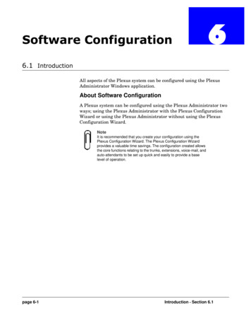
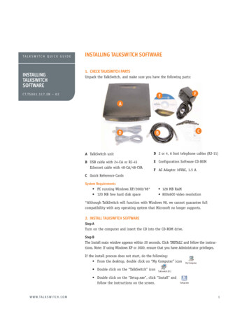
BEFORE YOU BEGINBefore you configure your TalkSwitch system to make and receive VoIP calls, reviewthe network planning information provided in this section.Ensure there is a TalkSwitch 48-CVA or VoIP gateway in each locationIn order to create a multi-location VoIP network, a TalkSwitch 48-CVA or a VoIPgateway, such as a Mediatrix 2102, is required at each location. The Mediatrix 2102 isa TalkSwitch-certified third-party SIP gateway that can be used by small branch officesor teleworkers.Note: Check with TalkSwitch Support before purchasing third-party SIP devices toensure they operate with TalkSwitch.Each location in a multi-location network can support up to 4 TalkSwitch 48-CVAunits, with a maximum of 32 local extensions and 16 VoIP lines per location. You cancontact TalkSwitch Support for assistance in setting up large multi-location networks.The following is an example of a multi-location network where two locations areequipped with TalkSwitch systems and a teleworker is equipped with a Mediatrix 2102device. TalkSwitch and the Mediatrix 2102 route VoIP calls over the Internet, whilelocal calls are routed over the traditional telephone network.New York officeTelephoneNetworkSan Francisco officeTalkSwitch 48-CVAInternetMiami homeTalkSwitch 48-CVAMediatrix 2102FIGURE 1. Multi-location network with VoIP calling2TA L K S W I TC H Vo I P C O N F I G U R AT I O N G U I D E
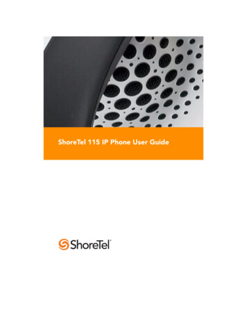
Ensure TalkSwitch is connected to a LAN and IP networkIn order to make and receive VoIP calls, ensure the TalkSwitch system in each locationis connected to a Local Area Network (LAN), consisting of a PC (for configurationpurposes), Ethernet switch and router, or a router with an integrated switch (such asthe Linksys BEFSR81).Note: For optimal performance, you will need a reliable high-speed broadbandInternet connection in each location. ‘Lite’ broadband connections are not suitablefor simultaneous voice and data traffic.ROUTER with integrated SWITCHFIGURE 2. TalkSwitch network configurationUncertain of your VoIP call capacity? Visit our website at:www.talkswitch.com/voip/voip capacity.php to perform a VoIP Bandwidth Test,which will determine your VoIP call capacity based on your current Internetconnection speed.Prioritizing voice trafficIf you plan on sharing your Internet connection among your computers andTalkSwitch (between data and voice), then it is critical that the voice traffic haspriority over the data traffic. Some routers, such as the Linksys BEFSR81, supportQuality of Service routing (QoS) for this purpose. If your router supports QoS, ensurethat it is configured to provide priority to voice traffic (see your router documentationfor configuration details).W W W. T A L K S W I T C H . C O M3
Forwarding voice data through a router/firewallIn order to pass through a router’s firewall, voice data received by your network mustbe mapped to the appropriate TalkSwitch unit. TalkSwitch uses UPnP (Universal Plugand Play) to automate the mapping of firewall ports for forwarding VoIP data. Many oftoday’s routers support UPnP for port mapping/forwarding. If your router supports UPnP,ensure that it is enabled (see your router documentation for configuration details).If a router does not support UPnP, you will need to configure it to map specificports to TalkSwitch. The following describes which ports to map to TalkSwitch: To allow SIP Signaling data* to be forwarded to TalkSwitch, firewall port 5060 must be mapped to the TalkSwitch unit known as the Local Proxy. By default, this is thelowest numbered 48-CVA unit on a LAN. For example, if TalkSwitch unit 1 is a 48-CVAunit, then port 5060 should be mapped to this unit. SIP Signaling is done using UDP.Note: The IP Configuration window of the TalkSwitch Software indicates (with anasterix) which TalkSwitch unit is acting as the Local Proxy (see Step 1 of this guide— Configure TalkSwitch to make VoIP calls).In order for voice traffic to be forwarded to TalkSwitch, corresponding ports must bemapped to each TalkSwitch 48-CVA unit. The following table shows the firewall portsto map to each TalkSwitch 48-CVA unit on a LAN.TABLE 1. Firewall portsa required open for VoIP communication with TalkSwitchDescriptionTypeCVA unit 1CVA unit 2CVA unit 3TCVA unit 4Voice TrafficUDP6000-60066010-60166020-60266030-6036a. The port numbers shown are the reserved default port numbers. To re-assignthese numbers, contact TalkSwitch Technical Support. If you plan on configuring TalkSwitch remotely, you will need to map port 9393 tothe TalkSwitch unit that is being configured. For information on configuringTalkSwitch remotely, refer to the TalkSwitch Remote Configuration Quick Guide.Configuration is done using TCP.For information on configuring a router for port forwarding, itch with DSL Internet serviceIf a location has DSL Internet service, ensure that the router’s Point-to-Point Protocolover Ethernet (PPPoE) settings are configured for connecting to the Internet service.Refer to the documentation provided with the router and check with the InternetService Provider (ISP) for configuration information.*4The Session Initiation Protocol (SIP) Signaling data initiates a VoIP session in an IP network.TA L K S W I TC H Vo I P C O N F I G U R AT I O N G U I D E
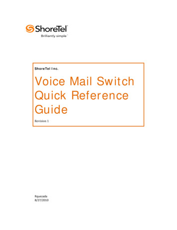
Determine which TalkSwitch will act as the SIP server for yourVoIP networkThe TalkSwitch 48-CVA has a built-in Session Initiation Protocol (SIP) server to manageall SIP devices in a TalkSwitch multi-location network. The TalkSwitch systemdesignated as the SIP server will contain the registration information for all othersystems and SIP devices in the network. When making or receiving a VoIP call, a devicewill register with the SIP server, which will then route the call to the appropriatelocation.Note: If interfacing TalkSwitch with a VoIP Service Provider, the Service Providerwill act as the SIP server for your network.In the following example, the TalkSwitch system in the San Francisco office isdesignated as the SIP server. When a VoIP call is placed from any location, the phonenumber is resolved by the SIP server and the call is routed to the appropriate office.New York officeTelephoneNetworkSan Francisco officeTalkSwitch 48-CVAInternetMiami homeTalkSwitch 48-CVA(SIP server)Mediatrix 2102FIGURE 3. Multi-location network with designated SIP serverW W W. T A L K S W I T C H . C O M5
Which location and TalkSwitch system should I configure as the SIP server?Any TalkSwitch 48-CVA system in a multi-location network can act as the SIP server.However, we recommend that the location have a static, rather than a dynamic, publicIP address. Since a static IP address is fixed and does not change, a consistentconnection can be kept among all locations and the SIP server.If having a static IP address is not possible, you can obtain a Fully Qualified DomainName (FQDN) from a Dynamic Domain Name Service (DDNS) provider. One such provideris DynDNS. A DDNS handles dynamic IP address changes and maps IP addresses to yourFQDN, thereby making IP address changes transparent to TalkSwitch. Check whichDDNS your router can support. For more information on DynDNS, visit:http://www.dyndns.org/services/dyndns.Note: Only one TalkSwitch system in a multi-location VoIP network should bedesignated as the SIP server.Configuring TalkSwitch to act as the SIP server is described in Step 2 of thisguide — Configure TalkSwitch to act as the SIP Server.For more information about the SIP server and for information on optimizing your IPnetwork for VoIP, refer to the TalkSwitch Installation and User Guide for theTalkSwitch 48-CVA.Establish a dialing plan for your networkSince you are creating a private VoIP network, you must assign phone numbers to VoIPtrunks (lines) in TalkSwitch. A form has been provided in this guide to help you recorda dialing plan for your network (see Appendix A — TalkSwitch VoIP NetworkAdministration Form).Note: If interfacing TalkSwitch with a VoIP Service Provider, the Service Providerwill assign VoIP phone numbers for your network.6TA L K S W I TC H Vo I P C O N F I G U R AT I O N G U I D E
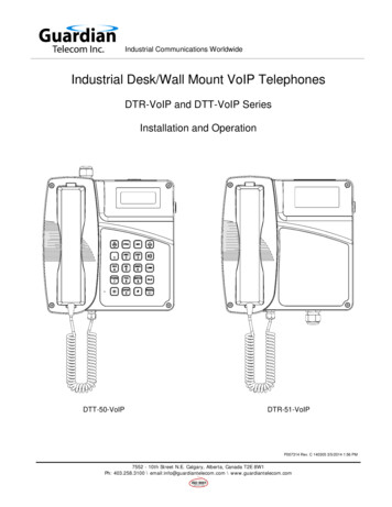
Choosing phone numbers for VoIP linesEach TalkSwitch 48-CVA unit supports 4 VoIP lines. Up to 3 phone numbers can beassigned to each of the 4 lines so that unique call handling scenarios can beconfigured for up to 12 numbers per unit. Phone numbers for VoIP lines can be 3 ormore digits in length.TalkSwitch supports 50 VoIP location numbers (250 to 299) that permit directdialing from any extension or Auto Attendant. Numbers outside of this range can alsobe assigned to VoIP lines and accessed using Hunt Groups. Note: Each phone numberassigned to a VoIP line must be unique in a multi-location network. Assigning phonenumbers to VoIP lines is described in Step 4 of the configuration section of thisguide — Assign Phone Numbers to VoIP Lines.In the following example, four VoIP location numbers are assigned to VoIP lines in SanFrancisco (251 to 254), four are assigned to VoIP lines in New York (261 to 264), andone is assigned to the residential office in Miami (271). These phone numbers can bedialed directly from an extension or from an Auto Attendant from any locationwithin the network.New York Office261262263264TelephoneNetworkSan Francisco officeTalkSwitch 48-CVAInternet251252253254TalkSwitch 48-CVA(SIP server)Miami home271Mediatrix 2102FIGURE 4. Multi-location network with assigned phone numbersW W W. T A L K S W I T C H . C O M7
STEP 1 – CONFIGURE TALKSWITCH TO MAKE VOIP CALLSEach TalkSwitch system in a multi-location network must be configured with bothlocal IP and public IP address information. These addresses are used to direct VoIP callsto the appropriate location. Each TalkSwitch unit in a system will have a differentlocal IP address.Set the TalkSwitch local IP addressThe following steps describe how to set the local IP address(es) of a TalkSwitch system:1. Open the TalkSwitch configuration software by double-clicking the TalkSwitch iconon your Desktop or, from the Windows Start menu, select Programs, the TalkSwitchfolder, and click TalkSwitch.2. In the TalkSwitch System Configuration window, select System Information andthen IP Configuration from the menu at the left.3. TalkSwitch is factory configured to use DHCP (Dynamic Host ConfigurationProtocol) to automatically obtain its System IP Settings. If the location has a DHCPserver, which is typically a function of the router, the fields on the screen willautomatically be filled in with the correct IP information. Click Use the followingIP and DNS information to ‘lock in’ these settings and ensure they are saved as thesystem IP settings.4. If the location does not have a DHCP server, the System IP Settings fields will notbe filled in. Click Use the following IP and DNS information and enter the IPaddress(es), Subnet mask, Default Gateway, Preferred DNS Server, and AlternateDNS Server information in the appropriate fields. For details on these settings referto the TalkSwitch Installation and User Guide for the 48-CVA.Note: Unit 1 IP Address designates the local IP address of TalkSwitch unit 1. Ifthere are multiple units in a system, enter the IP addresses of all units in thesystem (Unit 2 IP Address, Unit 3 IP Address, Unit 4 IP Address).2348TA L K S W I TC H Vo I P C O N F I G U R AT I O N G U I D E
Set the TalkSwitch public IP addressThe public IP address of a TalkSwitch system is assigned by your Internet ServiceProvider. Depending on the type of service, you will either have a dynamic or static IPaddress. If you are unsure which type you have, contact your Internet Service Provider.The following steps describe how to set the public IP address of a TalkSwitch system:1. Specify the Type of Public WAN IP for Internet Connection by selecting eitherdynamic or static from the drop-down list.If this TalkSwitch system will act as the SIP server for a network, we recommendhaving a static Public IP address. For more information on the SIP server, refer toDetermine which TalkSwitch system will act as the SIP server for your VoIP network inthe Before you Begin section of this guide.2. If this TalkSwitch system will act as the SIP server for a network and has a dynamicPublic IP address, enter the Fully Qualified Domain Name (FQDN) associated withthe Public IP address. If the address is static, leave this field blank.You can obtain a FQDN from a Dynamic Domain Name Service (DDNS) provider suchas DynDNS (visit http://www.dyndns.org/services/dyndns). Check which DDNSyour router can support.12W W W. T A L K S W I T C H . C O M9
STEP 2 – CONFIGURE TALKSWITCH TO ACT AS THE SIP SERVERThe following steps describe how to configure a TalkSwitch system to act as the SIPserver (Redirect Proxy/Registrar). Only one TalkSwitch system in a multi-locationnetwork can be configured as the SIP server. For information on the SIP server, seeDetermine which TalkSwitch system will act as the SIP server for your VoIP network inthe Before you Begin section of this guide.To configure TalkSwitch to act as the SIP server:1. In the TalkSwitch System Configuration window, select System Information andthen VoIP Configuration from the menu on the left.2. Select This TalkSwitch location is the Proxy/Registrar. The Public IP address orFully Qualified Domain Name will automatically be populated in the Proxy ServerName and Registrar Server Name fields.3. To enable authentication, select yes (digest) from the drop-down list belowRegistrar Authentication. Using authentication will allow only authorized devicesto access the network.4. If Authentication has been enabled, enter a User/Account name (for example,ABC) and system Password.Note: The Outbound Proxy and Realm/Domain fields are only required when thesystem is being provisioned with a VoIP service provider; refer to thedocumentation for configuring TalkSwitch with the specific service.132410TA L K S W I TC H Vo I P C O N F I G U R AT I O N G U I D E
STEP 3 – CONFIGURE TALKSWITCH TO REGISTER WITHTHE SIP SERVERTo make and receive VoIP calls, TalkSwitch systems must be configured to register withthe system designated as the SIP server. This step describes how to configure aTalkSwitch system to register with the SIP server.The information filled in for all systems should match the information filled in for thesystem designated as the SIP server in Step 2 — Configure TalkSwitch to act as the SIPServer.1. In the TalkSwitch System Configuration window, select System Information andthen VoIP Configuration from the menu on the left.2. Enter the Proxy Server Name and Registrar Server Name in the appropriate fields.These should be the same as those specified for the SIP server.3. If authentication was enabled for the SIP server, then enter the User/Accountname and system Password in the appropriate fields. These should be the same asthat specified for the SIP server.Note: The Outbound Proxy and Realm/Domain fields are only required when thesystem is being provisioned with a VoIP service provider; refer to thedocumentation for configuring TalkSwitch with the specific service.123W W W. T A L K S W I T C H . C O M11
STEP 4 – ASSIGN PHONE NUMBERS TO VOIP LINESThe following steps describe how to assign phone numbers to VoIP lines. Phonenumbers must be assigned to the VoIP lines of each TalkSwitch 48-CVA in amulti-location network. For information on VoIP phone numbers, see Establish adialing plan for your network in the Before you Begin section of this guide.To assign phone numbers to VoIP lines:1. In the TalkSwitch System Configuration window, select System Information andthen VoIP Lines from the menu on the left.2. Select Line 1 and Click on Phone Number 1, a dialog box opens requesting you toenter a phone number.3. Enter a unique phone number to be used by callers dialing this TalkSwitchlocation. To simplify inter-branch calling between TalkSwitch locations, werecommend using the TalkSwitch VoIP location numbers 250-299, as these numberscan be directly dialed from any extension or from an Auto Attendant.Note: Ensure that each number assigned is unique in the network.For each TalkSwitch 48-CVA unit in a system, you can assign up to three VoIPphone numbers per line, increasing the number of inbound VoIP call handlingoptions available. You can set these additional numbers at any time.4. Repeat the above steps for Lines 2, 3 and 4.5. For systems with multiple units, repeat the process for each TalkSwitch 48-CVAunit in the system (click on the tabs labeled ‘TalkSwitch 1’, ‘TalkSwitch 2’,‘TalkSwitch 3’, and ‘TalkSwitch 4’).21123TA L K S W I TC H Vo I P C O N F I G U R AT I O N G U I D E
Assigning numbers outside of the VoIP location number rangeNumbers outside of the VoIP location number range (outside of the 250 to 299 range)can be assigned to VoIP lines and accessed using Hunt Groups. Typically these numbersare assigned when most of the VoIP location numbers have already been allocated.Using Hunt Groups to access VoIP linesTo use Hunt Groups to access VoIP lines, perform the following steps:1. From the System Information menu, select VoIP Lines.2. Assign phone numbers outside of the VoIP location number range to VoIP lines (forexample, ‘4001’ to VoIP Line 1, ‘4002’ to line 2, ‘4003’ to line 3, ‘4004’ to line 4).123. From the System Information menu, select Line Hunt Groups and assign a HuntGroup (for example ‘88’) to access VoIP lines (select ‘VoIP Lines’ as the Line Typeand ensure all VoIP lines are selected).3In this example, callers can dial ‘88’ from any extension to get a VoIP dialtone. Thendial ‘4001’ to ‘4004’ to reach that location.W W W. T A L K S W I T C H . C O M13
Using the Busy Forwarding feature for VoIP linesThe Busy Forwarding feature is similar to the phone company’s ‘Rollover/BusyForwarding’ service. To use the Busy Forwarding feature for VoIP lines:1. From the System Information menu, select VoIP Lines.2. Assign a VoIP location number such as ‘251’ to VoIP Line 1. Next, assign num
NOTE: For TalkSwitch provisioning with a VoIP service provider, please refer to the documentation located on our website www.talkswitch.com. Who should use this guide This guide is intended for customers who have: Purchased the TalkSwitch 48-CVA phone system and wish to configure it