Transcription
6RIWZDUH &RQILJXUDWLRQ ,QWURGXFWLRQAll aspects of the Plexus system can be configured using the PlexusAdministrator Windows application.About Software ConfigurationA Plexus system can be configured using the Plexus Administrator twoways; using the Plexus Administrator with the Plexus ConfigurationWizard or using the Plexus Administrator without using the PlexusConfiguration Wizard.NoteIt is recommended that you create your configuration using thePlexus Configuration Wizard. The Plexus Configuration Wizardprovides a valuable time savings. The configuration created allowsthe core functions relating to the trunks, extensions, voice-mail, andauto-attendants to be set up quick and easily to provide a baselevel of operation.page 6-1Introduction - Section 6.1
Software Configuration 6RIWZDUH FRQILJXUDWLRQ ZLWK 3OH[XV &RQILJXUDWLRQ :L]DUGSeveral steps that must be completed in order to configure a Plexus systemusing the Plexus Administrator with the Plexus Configuration Wizard. TheWizard will create all the users and trunks and place them according to thephysical layout of the system. You will be able to modify settings after thePlexus Configuration Wizard has created the configuration.1 “Determine the structure of the system” - section 6.4.2 “Physically insert peripheral cards into the cabinet” - section 6.5.3 Follow the steps in Chapter 5, "Plexus Configuration Wizard". (The Wizardwill create a working configuration. If modifications are necessary,continue to step 4.)4 Launch Plexus Administrator if it is not already open (see “Launch PlexusAdministrator” - section 6.6).5 Open the created configuration (see “Using an existing configuration file” section 6.8).6 Go to “Configure Auto-Attendant Interface (AAI) card” - section 6.10. Followall subsequent steps and sections to modify the configuration.Section 6.2- Software configuration - with Plexus Configuration Wizardpage 6-2
Software Configuration 6RIWZDUH FRQILJXUDWLRQ ZLWKRXW 3OH[XV &RQILJXUDWLRQ :L]DUGThe outline that follows discusses the steps that must be completed in order toconfigure a Plexus system using the Plexus Administrator without using thePlexus Configuration Wizard. Several procedures and the various systementities (i.e. Users, User Groups, Trunks, Trunk Groups, Extension Ports, andTrunk Ports) are addressed. While all steps must be completed in order tosuccessfully configure a system, the user does not need to complete each stepaccording to the sequence shown below. The Plexus Administrator is fullymodular and allows the user to address each parameter in any order. Howeverthere are certain dependencies e.g., create a user before configuring the user’scoverage. This Software Configuration section is organized according to thefollowing sequence. This sequence is followed in order through the rest of thischapter.1 “Determine the structure of the system” - section 6.42 “Physically insert peripheral cards into the cabinet” - section 6.5.3 “Launch Plexus Administrator” - section 6.6.4 “Start a new configuration” - section 6.7.5 “Complete the peripheral card layout” - section 6.9.6 “Configure Auto-Attendant Interface (AAI) card” - section 6.10.7 “Configure Integrated Voice Processor (IVP) card” - section 6.11.8 “Create users” - section 6.12 and “Create user groups” - section 6.13.9 “Assign users to user groups” - section 6.14.10 “Create trunks” - section 6.15 and “Create trunk groups” - section 6.16.11 “Assign trunks to trunk groups” - section 6.17.12 “Configure AEI extension ports” - section 6.18 and “Configure DEIextension ports” - section 6.19.13 “Configure ATI trunk ports” - section 6.20.14 “Configure system parameters” - section 6.21.15 “Configure users” - section 6.22 and “Configure user groups” - section 6.23.page 6-3Software configuration - without Plexus Configuration Wizard - Section 6.3
Software Configuration16 “Configure trunks” - section 6.24 and “Configure trunk groups” - section6.25.17 “Saving a configuration” - section 6.26.18 “Establishing a link” - section 6.27.19 “Uploading the configuration file” - section 6.28.20 “Updating the system clock” - section 6.29.21 “Updating Plexus key telephone programming” - section 6.30.Section 6.3- Software configuration - without Plexus Configuration Wizardpage 6-4
Software Configuration 'HWHUPLQH WKH VWUXFWXUH RI WKH V\VWHP Determine the flexible numbering plan that the phone system will follow.The numbering plan should be designed for optimum organization, clarity,and growth. User IDs can consist of 2-5 digits as defined in the width parameter (Dial Plan tab). The range is based upon the From and To parameters (Dial Plan tab). For example, ifthe Range is (From) 1 to (To) 4 with a Width of 3. IDs could be from 100 through499. Likewise, if the Range is (From) 1 to (To) 4 with a Width of 4. IDs could befrom 1000 through 4999. The numbering plan will need to include: User; User Group, Trunk; Trunk Group;Auto Attendant; and Voice IDs.NoteThe Integrated Voice Processor (auto attendant and voice mailboxes) will onlysupport IDs of 1-4 digits with the highest ID being 8999. If the auto attendant orvoice mailbox features will be used, The user IDs must fall into this range. Determine the Access Digits for the system. What number will the user dial to access an outside line (i.e., trunk)? What number will the user dial to reach the system operator? Determine the number of groups on the system and their names. What employees or stations will belong to what group? User Groups departments, organizational groups, teams, sections. Determine how many trunks will be available on the system. Trunks outside phone lines. Determine how the trunks should be grouped. Trunk Groups groups of outside phone lines.page 6-5 Determine if the organization will have an Auto-Attendant. Determine if the organization will have Plexus Integrated Voice Mail. Determine how calls will be routed to users and user groups. Determine how calls should be managed during the day, night, andweekends. Determine coverage (backup) for each user or user Group.Determine the structure of the system - Section 6.4
Software Configuration Determine the features and privileges for each user (e.g., Hold Time-outs,Override capabilities, Call Intrusion capabilities, Toll Restrictions etc.). Determine how calls will be distributed to members of each user group.Section 6.4- Determine the structure of the systempage 6-6
Software Configuration 3K\VLFDOO\ LQVHUW SHULSKHUDO FDUGV LQWR WKH FDELQHWRefer to “Inserting Peripheral Cards” - section 4.3.page 6-7Physically insert peripheral cards into the cabinet - Section 6.5
Software Configuration /DXQFK 3OH[XV GPLQLVWUDWRULaunch the Plexus Administrator as follows:1 Click on.2 Select Programs.3 Select Plexus.4 Click on Plexus Administrator.After launching Plexus Administrator, the following window displayed:Section 6.6- Launch Plexus Administratorpage 6-8
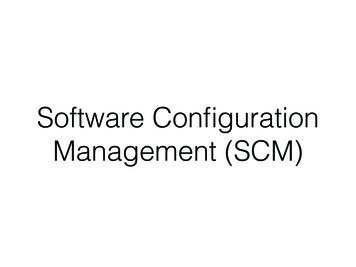
Software Configuration 6WDUW D QHZ FRQILJXUDWLRQTo start a new configuration:1 From the File menu on the initial window, select New.2 Select the type of System being configured (i.e., Macro or Micro).3 If only one cabinet is in use, leave Unit 1 set to None.page 6-9Start a new configuration - Section 6.7
Software Configuration 8VLQJ DQ H[LVWLQJ FRQILJXUDWLRQ ILOHIf you are modifying a configuration using an existing configuration file:1 From the File menu on the initial window, select Open.2 Select the desired configuration file.Plexus configuration files have an extension of .zdb. E.g., the PlexusConfiguration Wizard will create a configuration file named wiz-cfg.zdbSection 6.8- Using an existing configuration filepage 6-10
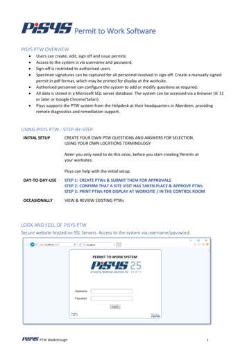
Software Configuration &RPSOHWH WKH SHULSKHUDO FDUG OD\RXW 3HULSKHUDO FDUG OD\RXW1 Click on the System tab to display the peripheral card layout.page 6-11Complete the peripheral card layout - Section 6.9
Software Configuration2 With an image of the applicable cabinet (i.e. Macro Plexus or Micro Plexus)displayed, right-click on the various slots and select the card (ATI, AEI,etc.) that have been physically inserted.An image of the selected card will appear in the slot.3 Fill the slots on the Macro Plexus system from left to right as follows:ATI-Analog Trunk Interface cardsAAI-Auto-Attendant Interface card (optional)AEI-Analog Extension Interface cardsDEI-Digital Extension Interface cardsILI-Inter-Unit Link Interface card (optional)-slot labeled 8DXP-Digital Switch Processor-slot labeled “9”IVP-Integrated Voice Processor card (optional)-slot labeled 10For digital line Interface cards (T1, E1, ISDN) or Direct Inward Dial(DID) Trunk Interface cards, refer to the Interface card’s individualchapter.Section 6.9- Complete the peripheral card layoutpage 6-12
Software Configuration4 For The Micro Plexus system, right-clicking in an empty slot will show thecards that are allowed for that slot. Other card choices will be grayed out.NoteThe Digital Switch Processor (DXP) card may only be placed in the slot inwhich it appears. The Inter-Unit Link Interface (ILI) card may only be placed inthe rear slot of the Micro Plexus system and the slot labeled 8 on the MacroPlexus system.Refer to the Installation section for details on inserting peripheral cards. OWHUQDWLYH PHWKRG WR OD\RXW SHULSKHUDO FDUGV1 Physically insert peripheral cards.2 Start Plexus Administrator.3 From the File menu, select New.4 Select the type of cabinet that is being configured, Micro or Macro.5 From the Link menu, select Open.6 From the Verify menu, select Read.Upon completing the read, the following message will appear on the screen:Verify: Read Operation Complete 7 Click OK.8 From the Verify menu, select Synchronize.NoteThe Digital Switch Processor (DXP) card may only be placed in the slot inwhich it appears. The Inter-Unit Link Interface (ILI) card may only be placed inthe rear slot of the Micro Plexus system and the slot labeled 8 on the MacroPlexus system.page 6-13Complete the peripheral card layout - Section 6.9
Software Configuration &RQILJXUH XWR WWHQGDQW ,QWHUIDFH , FDUGRefer to chapter 15, "Automated Attendant Interface".Section 6.10- Configure Auto-Attendant Interface (AAI) cardpage 6-14
Software Configuration &RQILJXUH ,QWHJUDWHG 9RLFH 3URFHVVRU ,93 FDUGRefer to chapter 9, "Integrated Voice Processor".page 6-15Configure Integrated Voice Processor (IVP) card - Section 6.11
Software Configuration &UHDWH XVHUV &UHDWH XVHUV1 Click on the User tab to display the User and User Group.2 Click on the Create button in the User Window and enter a User ID sequencewithin the dial plan.3 Create additional users by clicking on the Create button or by pressingENTER on the keyboard. ERXW XVHUVA user is an employee, employee alias, or device that will utilize the system forthe purpose of placing or receiving calls. Jane Doe (employee) Salesperson X (employee alias) Device (Dss Console, modem, credit card scanner, fax machine)Users can utilize several IDs by logging in or signing in to the system, dependingon the functions they are to perform. Therefore there does not need to be a oneone relationship between user IDs and extension ports. ERXW WKH 8VHU ,' VHTXHQFHThe User ID sequence is the start number of the range of logical IDs to beassigned to system users. Users are assigned user IDs based on the establisheduser ID sequence. The user ID sequence may be any number based on the DialNumber Range (refer to System Parameters: Dial Plan). Default settings call fora range from 1 to 4 with a width of 3. Using these settings, the user ID sequencemay be any number between 100 and 499.ExampleIf the User ID sequence entered is 100, the first user created is assigned a user ID of 100.Each additional user created is assigned an ID based on the established sequence. Fiveusers on a system with a user ID sequence of 100, would be 100, 101, 102, 103, and 104.TipTo insert or start a new sequence with a new starting number, click on the Create buttonwhile holding down SHIFT on the keyboard. Newly added sequences are automaticallyordered.See “Configure users” - section 6.22 for more details.Section 6.12- Create userspage 6-16
Software Configuration &UHDWH XVHU JURXSV &UHDWH XVHU JURXSV1 Click on the User tab to display the User and User Group dialog windows.2 Click on the Create button in the User Group Window and enter a UserGroup ID sequence within the dial plan.3 Create additional groups by clicking on the Create button or by pressingENTER on the keyboard. ERXW XVHU JURXSV User Groups are groups of users (individuals or functions) who share certainsystem call routing features. User groups are typically used to establishcertain departmental areas (e.g., Sales, Technical Support, etc.) for thepurpose of receiving calls. ERXW WKH XVHU JURXS ,' VHTXHQFHThe user group ID sequence is the start number of the range of logical IDs to beassigned to user groups. The user group ID sequence may be any number basedon the Dial-Number Range (refer to System Parameters: Dial Plan). Defaultsettings call for a range from 1 to 4 with a width of 3. Using these settings, theuser group ID sequence may be any number between 100 and 499.If the user group ID sequence entered is 300, the first user group created isassigned a user group ID of 300. Each additional user group created is assignedan ID based on the established sequence. Five user groups on a system with auser group ID starting sequence of 300, would be 301, 302, 303 and 304.TipTo insert or start a new sequence with a new starting number, click on the Create buttonwhile holding down SHIFT on the keyboard. Newly added sequences are automaticallyordered.See “Configure user groups” - section 6.23 for more details.page 6-17Create user groups - Section 6.13
Software Configuration VVLJQ XVHUV WR XVHU JURXSV VVLJQ XVHUV WR XVHU JURXSVEach user may be a member of any number of user groups.1 Ensure that users and user groups have been created.2 Click on the user so that it becomes highlighted.3 Click again on the user and hold down the left mouse button.4 Drag the user over to the desired user group.The user group name will become highlighted.5 With the desired user group highlighted, release the mouse button. ERXW DVVLJQLQJ XVHUV WR XVHU JURXSVThe first user assigned to a user group converts the user group icon from a sheetof paper to a folder. Double-clicking on a user group folder icon displays themembers of the user group.TipTo change the order in which users are listed in the user group, click on the user so that itbecomes highlighted and drag it to the desired position in the user group.CTRL and SHIFT may be used to select multiple users. Click on the first user so that itbecomes highlighted. Hold down CTRL and select additional users in the desired order. Holddown SHIFT and use Ç and È to select a consecutive list of users. A selected group ofusers may be assigned to a user group in one drag and drop motion.Section 6.14- Assign users to user groupspage 6-18
Software Configuration &UHDWH WUXQNV &UHDWH WUXQNV1 Click on the Trunk tab to display the Trunk and Trunk Group dialogwindow.2 Click on the Create button in the trunk window and enter a trunk IDsequence within the dial plan.3 Create additional trunks by clicking on the create button or by pressingENTER on the keyboard. ERXW WUXQNVTrunks and trunk groups determine how a user will place external calls anddetermine how inbound calls are routed. Trunk groups are used for allocationpurposes (e.g., to permit users access to groups of outside lines). ERXW WKH WUXQN ,' VHTXHQFHThe Trunk ID sequence is the start number of the range of logical IDs to beassigned to the trunks on the system. Trunks are assigned sequential Trunk IDsbased on the established Trunk ID sequence. The trunk ID sequence may be anynumber based on the Dial-Number Range (refer to System Parameters: DialPlan). Default settings call for a range from 1 to 4 with a width of 3. Using thesesettings, the trunk ID sequence may be any number between 100 and 499.ExampleIf the Trunk ID sequence entered is 201, the first trunk created is assigned a Trunk ID of 201.Each additional trunk created is assigned an ID based on the established sequence. Fivetrunks on a system with a Trunk ID sequence of 201, would be 201, 202, 203, 204 and 205.TipTo insert or start a new sequence with a new starting number, click on the Create buttonwhile holding down SHIFT on the keyboard. Newly added sequences are automaticallyordered.See “Configure trunks” - section 6.24 for more details.page 6-19Create trunks - Section 6.15
Software Configuration &UHDWH WUXQN JURXSV &UHDWH WUXQN JURXSV1 Click on the Create button in the trunk group Window and enter a trunkgroup ID sequence within the dial plan.2 Create additional trunk groups by clicking on the Create button or bypressing ENTER on the keyboard. ERXW WUXQN JURXSVTrunks and trunk groups determine how a user will place external calls anddetermine how inbound calls are routed. Trunk groups are used for allocationpurposes (e.g., to permit users access to groups of outside lines). Trunk groupswill be assigned sequential trunk group IDs based on the established trunkgroup ID sequence. ERXW WKH WUXQN JURXS ,' VHTXHQFHThe trunk group ID sequence is the start number of the range of logical IDs to beassigned to the trunk groups on the system. Trunk groups are assignedsequential trunk group IDs based on the established trunk group ID sequence.This sequence may be any number based on the Dial-Number Range (refer toSystem Parameters: Dial Plan). Default settings call for a range from 1 to 4 witha width of 3. Using these settings, the trunk group ID sequence may be anynumber between 100 and 499.ExampleIf the trunk group ID sequence entered is 400, the first trunk group created is assigned aTrunk Group ID of 401. Each additional trunk group created is assigned an ID based on theestablished sequence. Five trunk groups on a system with a trunk group ID sequence of401, would be 401, 402, 403, 404 and 405.TipTo insert or start a new sequence with a new starting number, click on the Create buttonwhile holding down SHIFT on the keyboard. Newly added sequences are automaticallyordered.See “Configure trunk groups” - section 6.25 for more detailsSection 6.16- Create trunk groupspage 6-20
Software Configuration VVLJQ WUXQNV WR WUXQN JURXSV VVLJQ WUXQNV WR WUXQN JURXSVTo assign a trunk to a trunk group, proceed as follows. Each trunk may be amember of more than one trunk groups.1 Ensure that both the trunk and trunk Group have been created.2 Click on the trunk so that it becomes highlighted.3 Click again on the trunk and hold down the left mouse button.4 Drag the trunk over to the desired trunk group.The trunk group name will become highlighted.5 With the desired trunk group highlighted, release the mouse button. ERXW DVVLJQLQJ WUXQNV WR WUXQN JURXSVThe first trunk assigned to a trunk group converts the trunk group icon from asheet of paper to a folder. Double-clicking on a trunk group folder icon displaysthe trunks in the trunk group.TipTrunks should be listed in trunk groups in an order opposite to the hunt (rollover) orderestablished by the phone company. Such an arrangement facilitates the use of the leastbusy trunks for outgoing calls. The order in which trunks are listed in the trunk group ischanged by clicking on the trunk so that it becomes highlighted and dragging it to thedesired position in the trunk group.CTRL and SHIFT may be used to select multiple trunks. Click on the first trunk so that itbecomes highlighted. Hold down CTRL and select additional trunks in the desired order.Hold down SHIFT and use and to select a consecutive list of trunks. A selected group oftrunks may be assigned to a trunk group in one drag and drop motion.Çpage
The outline that follows discusses the steps that must be completed in order to configure a Plexus system using the Plexus Administrator without using the Plexus Configuration Wizard. Several procedures and the various system entities (i.e. Users, User Groups, Trunks, Trunk Groups, Extension Ports, a