Transcription
Industrial Communications WorldwideIndustrial Desk/Wall Mount VoIP TelephonesDTR-VoIP and DTT-VoIP SeriesInstallation and OperationDTT-50-VoIPDTR-51-VoIPP007314 Rev. C 140305 3/5/2014 1:56 PM7552 - 10th Street N.E. Calgary, Alberta, Canada T2E 8W1Ph: 403.258.3100 \ email:info@guardiantelecom.com \ www.guardiantelecom.com
Guardian Telecom Inc.Installation and OperationDTR/DTT-VoIP Series TelephonesPoE DTR/T-VoIP Installation Guide P007314 Rev. CCOPYRIGHT NOTICE: 2014, Guardian Telecom Inc., ALL RIGHTS RESERVED.This manual and the related materials are the copyrighted property of Guardian TelecomInc. No part of this manual or related materials may be reproduced or transmitted, in anyform or by any means (except for internal use by licensed customers), without priorexpress written permission of Guardian Telecom Inc. This manual, and the products,software, firmware, and/or hardware described in this manual are the property of GuardianTelecom Inc. provided under the terms of an agreement between Guardian Telecom Inc.and the recipient of this manual, and their use is subject to that agreement and its terms.DISCLAIMER: Except as expressly and specifically stated in a written agreementexecuted by Guardian Telecom Inc., Guardian Telecom Inc. makes no representation orwarranty, express or implied, including any warranty or merchantability or fitness for anypurpose, with respect to this manual or the products, software, firmware, and/or hardwaredescribed herein, and Guardian Telecom Inc. assumes no liability for damages or claimsresulting from any use of this manual or such products, software, firmware, and/orhardware. Guardian Telecom Inc. reserves the right to make changes, without notice, tothis manual and to any such product, software, firmware, and/or hardware.OPEN SOURCE STATEMENT: Certain software components included in Guardianproducts are subject to the GNU General Public License (GPL) and Lesser GNU GeneralPublic License (LGPL) “open source” or “free software” licenses. Some of this OpenSource Software may be owned by third parties. Open Source Software is not subject tothe terms and conditions of the Guardian COPYRIGHT NOTICE or software licenses.Your right to copy, modify, and distribute any Open Source Software is determined by theterms of the GPL, LGPL, or third party, according to who licenses that software.Software or firmware provided by Guardian that is unrelated to Open Source Software iscopyrighted by Guardian, subject to the terms of Guardian licenses, and may not becopied, modified, reverse-engineered, or otherwise altered without explicit writtenpermission from Guardian Telecom Inc.TRADEMARK NOTICE: Guardian Telecom Inc. and the Guardian Telecom Inc. logos aretrademarks of Guardian Telecom Inc. Other product names, trademarks, and servicemarks may be the trademarks or registered trademarks of their respective owners.Toll-free 1-800-363-8010Phone (403) 258-3100Fax. (403) 253-4967www.guardiantelecom.comE-mail: sales@guardiantelecom.comPage 2
Guardian Telecom Inc.Installation and OperationDTR/DTT-VoIP Series TelephonesImportant Safety Instructions1.Read these instructions.2.Keep these instructions.3.Heed all warnings.4.Follow all instructions.5.Install in accordance with the manufacturer’s instructions.6.Do not install near any heat sources such as radiators, heat registers, stoves, or otherapparatus (including amplifiers) that produce heat.7.Only use attachments/accessories specified by the manufacturer.8.Refer all servicing to qualified service personnel.9.Prior to installation, consult local building and electrical code requirements.This product meets the applicable Industry Canada technical specifications. / Le présent matériel estconforme aux specifications techniques applicables d’Industrie Canada.If trouble is experienced with this equipment (DTR-VoIP and DTT-VoIP), for repair or warranty information, please contactGuardian Telecom at 1-800-363-8010. If the equipment is causing harm to the telephone network, the telephone companymay request that you disconnect the equipment until the problem is resolved.If this equipment requires AC power it is suggested that a surge arrestor be used.Page 3
Guardian Telecom Inc.Installation and OperationDTR/DTT-VoIP Series TelephonesTable of Contents1.Product Overview . 62.Typical System Installation . 63.Features . 74.Installation . 95.Wiring . 116.Operation . 117.Supported Protocols . 128.Supported SIP Servers . 129.DTR/DTT-VoIP Telephones Wiring . 129.1.Connections . 129.2.Connecting a Device to the Auxiliary Relay . 139.3.Identifying the Connector Locations and Functions. 149.4.Network Connectivity, and Data Rate . 159.4.1.Verify Network Activity . 159.5.RESET Switch. 169.5.1.Announcing the IP Address . 169.5.2.Restore the Factory Default Settings . 169.6.Adjust the Volume . 1610.Product Specifications . 1711.Field Repairs . 1812.Replacement Parts . 1913.Cleaning Tips for Guardian Telephones . 1914.Warranty . 2015.Disclaimer . 2016.Warning . 2017.Service Telephone Number . 2018.Feedback . 2019.Guardian Product Return . 21FiguresFigure 1 - Typical Installation . 6Figure 2 - Features (typical) . 8Figure 3 - Overall Dimensions . 8Figure 4 - Wall Installation of Base. 9Figure 5 - Wiring. 10Figure 6 - Temporary Mounting for Wiring . 11Figure 7 - Terminal Block Connections . 12Figure 8 - Auxiliary Relay Wiring Diagram . 13Figure 9 - Connector Locations . 14Figure 10 - Network Activity . 15Figure 11 - RESET Switch . 16TablesTable 1 - Connector Functions . 14Page 4
Guardian Telecom Inc.Installation and OperationDTR/DTT-VoIP Series TelephonesPackage Contents(1) DTR-VoIP or DTT-VoIP Telephone(1) Parts bag containing 1 Allen wrench and handset retainer(1) Mounting TemplateNote: Installation and Operation Manual, Setup and Configuration Manual, GuardianDiscovery Utility, Interoperability Guide, VoIP Technical Support, Firmware andAutoprovisioning template are all available at www.guardiantelecom.com.ModelsP3040 DTT-50-VoIP telephone with coil cord.P3041 DTT-60-VoIP telephone with armored handset cord.P3042 DTR-51-VoIP Ringdown telephone with coil cord.P3043 DTR-61-VoIP Ringdown telephone with armored handset cord.AccessoriesPOE – Injector – Auxiliary Power Supply(Contact Sales)Loud Ringers and Strobe LightsRegistering Your VoIP ProductTo register your VoIP product send an email to info@guardiantelecom.com.Be sure to include “Guardian VoIP Registration” in the subject field of your email.Include the following information:1. Company Name (Req'd)2. Address (Optional)3. Device Model (Req'd)4. Serial Number (Req'd)5. Date of purchase (Req'd)6. Name of Supplier (Req'd)7. Prime Contact (Req'd)8. Secondary Contact (Optional)9. Contact Info: Email Address(es) (Req'd)10. Phone Info: (Optional)Page 5
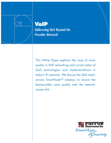
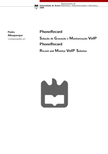
Guardian Telecom Inc.1.Installation and OperationDTR/DTT-VoIP Series TelephonesProduct OverviewDTT-VoIP Series Weather Resistant TelephonesDTR-VoIP and DTT-VoIP telephones provide safe, reliable communications in areas that are prone to high humidity, chemicalvapors, dust and physical abuse.These telephones are compatible with most SIP-based IP PBX servers that comply with SIP RFC 3261. Users can remotelymonitor and program settings through a web browser to configure telephones on their network.The DTR-51-VoIP and DTT-50-VoIP are standard models with a coiled handset cord and the DTR- 61-VoIP and DTT-60-VoIPare vandal resistant models with an armored handset cord.2.Typical System InstallationThe Voice-over-IP (VoIP) DTR-VoIP and DTT-VoIP Telephones are Power-over-Ethernet (PoE 802.3af) and Voice-over-IP(VoIP) two-way communications devices that easily connect into existing local area networks (LANs) with a single cableconnection.Figure 1 illustrates how the DTT-VoIP Telephones can be installed as part of a VoIP phone system.Generic PoE Hub123456EXTERNALDEVICESLAN 1LAN 2ALARMGuardian VoIP Emergency TelephonesGuardian VoIP Industrial TelephonesFigure 1 - Typical InstallationPage 6IP PBX Server
Guardian Telecom Inc.Installation and OperationDTR/DTT-VoIP Series Telephones3. FeaturesEnclosure-glass filled Polyester body construction Network web management interface Guardian discovery utility makes it easy todetect, locate and launch the web basedconfiguration screens Product self diagnostic testing availablethrough web interface Network adjustable speaker volume andmicrophone sensitivity Network downloadable firmware PoE 802.3af enabled (Powered-overEthernet) or alternate power source Web Based User Interface allows remotesetup of network, product operations,updates, self diagnostics and other functionalaccess.-weatherproof and corrosion resistant-reversible base for desk or wall mount-corrosion resistant hardware Temperature range -22 to 140 F( -30 to 60 C) Optional conformal coated circuit boards areresistant to corrosive agents (e.g. H2S, SO2 andNH3) and environments with high humidity Waterproof connections & stainless steelfittings for longer life Magnetic Reed Hook Switch - no moving parts Easily mounted on any sturdy vertical structure Programmable speed dial Noise Reducing Microphone allows a high levelof intelligibility in locations with high backgroundnoise Dual speeds of 10 Mbps and 100 Mbps Network/Web management Network configurable relay activation settings Dial Out Extension supports the addition ofcomma delimited pauses before sendingadditional DTMF tones Network downloadable product firmware Tamper proof design Autoprovisioning Configurable audio files Event activation – (see manual – eventssection) One year warranty Peer-to-peer capable Optional security screws with driver bit Armored Handset Cord (DTR-61 VoIP andDTT-60-VoIP only) withstands severe use Heavy duty K Type industrial handset Handset retainers to maintain on-hook status Modular parts for easy service Two M20 and one M12 cable entries Hearing-Aid Compatible & Receiver VolumeAdjustment Compatible with inductively coupled hearing-aiddevices Adaptive full duplex operation Compatible with most SIP-based IP PBXservers that comply with SIP (RFC 3261).Page 7
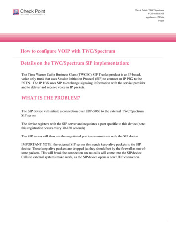
Guardian Telecom Inc.Installation and OperationDTR/DTT-VoIP Series TelephonesFigure 2 - Features (typical)Figure 3 - Overall DimensionsPage 8
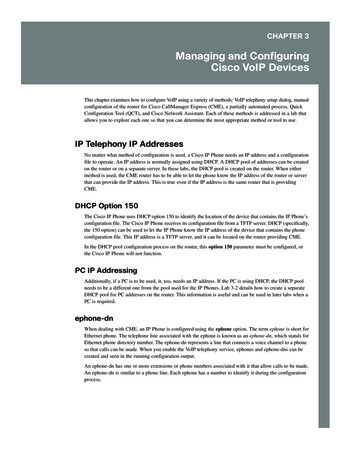
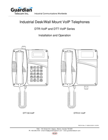
Guardian Telecom Inc.Installation and OperationDTR/DTT-VoIP Series Telephones9.4" [238mm]7.2" [184mm]8.7" [222mm]9.2" [234mm]Figure 4 - Wall Installation of Base4.InstallationEnclosureFollow all appropriate electrical codes and use only approved electrical fittings for theinstallation.To Avoid The Danger Of An Accidental Shock or Circuit Damageo If using an auxiliary power supply ensure it is unplugged during installation.o If using the onboard relay to control an external relay ensure power is off during installation.The telephone may be installed on a flat surface or wall mounted.Using the 3mm Allen Key provided, loosen the four faceplate captive screws to detach thefaceplate from the base.Desk Top ConfigurationIf the telephone is to be desk top mounted set the base in the desired location.Wall Mount ConfigurationIf the telephone is to be wall mounted choose a location that is free of obstructions and permitsspace for wiring. Mount the base with the deepest dimension on the bottom. Mount asfollows:ooooThe telephone weighs 3.95 kilograms (8.68 pounds), ensure that the mounting cansupport four times the weight of the unit; that is 15.8 kilograms (34.8 pounds).Wall anchors are not included; follow the manufacture’s instructions wheninstalling anchors.Mounting to concrete or cinder block. Lead expansion anchors with M4 (#8)screws are recommended.Mounting to drywall. Hollow wall anchors (Molly Bolts) with M4 (#8) screws arerecommended.Mounting to other surfaces. It is the responsibility of the installer to ensure that thebase is attached in such a way as to support the weight specified above.Install the handset retainer clips on the faceplate using the hardware supplied.Page 9See: Figure 3 - OverallDimensions
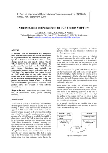
Guardian Telecom Inc.Installation and OperationDTR/DTT-VoIP Series TelephonesTOP VIEW OF VoIP PCBA 12J1J11JP5J8J7J4ETHERNETCABLEFigure 5 - WiringPage 10
Guardian Telecom Inc.Installation and OperationDTR/DTT-VoIP Series Telephones5.WiringWARNING: Use properly sized cable to ensure a gas/dust tight seal at the cable gland tomaintain an IP66 rating, (M12 – 2 to 5mm), (M20 – 8 to 13mm). Take care not to lose partsof the gland if the cap is removed.If the telephone is wall mounted temporarily hang the faceplate on the right side of the baseusing two of the faceplate screws. Be careful not to lose the "O" ring screw retainers.Determine if power to operate the telephone will be provided via the ethernet or if externalpower will be required. If external power is required install Guardian’s Auxiliary Power Supply orequivalent.Thread the bare end of the Network cable out of the enclosure through the gland and insert theplug into the RJ-45 connector on the PCBA.Tip: If cable diameter is not inthe range of the M12 or M20glands provided an approvedreducer and smaller gland canbe fitted.Connect the on board relay if utilized.See: Section 9.2 Connectinga Device to the AuxiliaryRelay andFigure 7 - Terminal BlockConnectionsIf using an alternate power supply connect to the terminal block.Tighten the cable glands securely.See: Figure 6 - TemporaryMounting for WiringSee: Figure 5 - WiringConnect the Network cable into the system.Determine that the telephone is properly connected by pressing the RESET switch for less thanfive seconds to announce the IP address.Mount the face plate and secure the captive screws to the base.Tip: Torque screws to 1.65ft/lbs (1.36Nm)Apply power to the telephone. Allow approx 30 seconds for the phone to boot up.If using an auxiliary power supply apply power to the conductors.If the built in Ring Detect Relay is utilized apply power to the conductors.ProgrammingSet up and configure if changes are required to the default settings.Tip: See Manual P007402 Setup and ConfigurationTest the unit by making calls to and from another unit.Figure 6 - Temporary Mounting for Wiring6.OperationOnce your Model DTT-VoIP Telephone has been properly installed and energized, operation is identical to most other singleline telephones.DTR-VoIP telephones will dial the programmed number when the handset is lifted.Adjust the receiver volume with the switch in the handset or on the keypad.Page 11
Guardian Telecom Inc.7.Installation and OperationDTR/DTT-VoIP Series TelephonesSupported ProtocolsThe DTT-VoIP Telephone with Keypad supports: SIP (Session Initiation Protocol) HTTP Web-based configurationProvides an intuitive user interface for easy system configuration and verification of DTT-VoIP Telephone withKeypad operations. DHCP ClientDynamically assigns IP addresses in addition to the option to use static addressing. TFTP ClientFacilitates hosting for the Autoprovisioning configuration file. RTPFacilitates autoprovisioning configuration values on boot. Audio EncodingsPCMU (G.711 mu-law)PCMA (G.711 A-law)Packet Time 20 ms8.Supported SIP ServersAs a SIP device, this product will operate with most IP PBX servers.9.DTR/DTT-VoIP Telephones Wiring9.1. ConnectionsFigure 7 shows the pin connections on the J9 (terminal block). This terminal block can accept a wire range from 16AWG to 26 AWG.Note: As an alternative to using PoE power 12 to 24 VDC at 500 mA can be supplied to the terminal block.TERMINAL BLOCK CONNECTION (J9)ALTERNATE POWER INPUT:1 NORMALLY OPEN COMMON2 NORMALLY OPEN CONTACT1RELAY CONTACT:0.5A AT 30VDC FOR CONTINUOUS LOADS23 12V TO 24V @ AT 500mA4 POWER GROUND5 RINGER 6 RINGER -123J9456WIRE INACCEPT WIRE RANGEUP TO 16 AWGFigure 7 - Terminal Block ConnectionsPage 12
Guardian Telecom Inc.9.2.Installation and OperationDTR/DTT-VoIP Series TelephonesConnecting a Device to the Auxiliary RelayThe ACR/ACT-VoIP Telephone incorporates one on-board relay located on the PCBA, whichenables users to control a low current external relay or device. An external relay could control aringer, strobe light, door lock or any other apparatus. The on board relay is protected by a 1See: Figure 8 Auxiliary Relay WiringDiagram.Amp, non-replaceable fuse. Power switched by the relay should not exceed 0.5Amps @ 30VDC. The PCBA is not designed to handle AC voltages.Warning: The relay circuitry contains a non-replaceable 250VAC 1A fu
The Voice-over-IP (VoIP) DTR-VoIP and DTT-VoIP Telephones are Power-over-Ethernet (PoE 802.3af) and Voice-over-IP (VoIP) two-way communications devices that easily connect into existing l