Transcription
White PaperWind Load Test and Calculation of theBase Station AntennaIssued dateApril 23, 2019VersionV1.0White Paper for the Wind Load Test and Calculation of the Base Station Antenna April, 2019Page 1 of 17
Contents Abstract Wind Load Calculation Methods P-BASTA New Standard and Antenna Wind Tunnel Test Definition of Huawei Antenna Wind Load Antenna Wind Load Engineering Application AppendixWhite Paper for the Wind Load Test and Calculation of the Base Station Antenna April, 2019Page 2 of 17
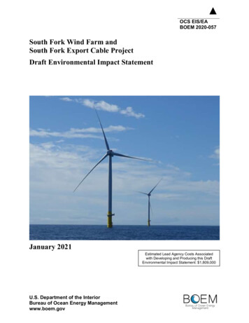
AbstractWind load is an important parameter fordesigning base station antenna structure,including the tower and supporting structures. Itdirectly affects the reliability of the antennaapplication and the safety of the tower.In recent years, with the rapid development ofMIMO, antennas are becoming increasinglyintegrated and the antenna size is constantlyincreasing, leading to more concerns for theimpact of antenna wind load on the tower. Theevaluation on tower safety and economicefficiency requires greater antenna wind loadcalculation accuracy.Since 2017, the standardization organizationNGMN-P-BASTA has established a base stationantenna wind load working group. This workinggroup has organized several workshops withmultiple antenna manufacturers and carriers tonormalize wind load standards and wind loadcalculation methods in the antenna industry. Thestandardized method of calculating the basestation antenna wind load has been released inthe P-BASTA V11.1 standard. Huawei developsthe antenna wind load specifications according tothe latest P-BASTA standard. This documentdescribes the wind load test and calculationmethods of Huawei base station antennas.Figure 1 Communication towerWhite Paper for the Wind Load Test and Calculation of the Base Station Antenna April, 2019Page 3 of 17
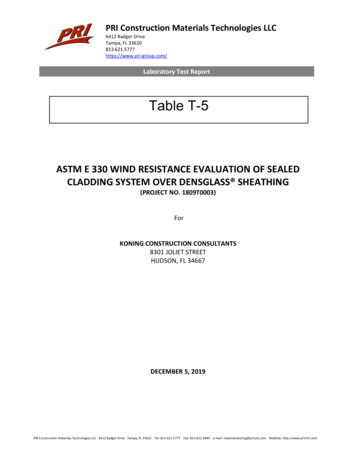
Wind Load Calculation MethodsAccording to Section 5.10 in NGMN-P-BASTARecommendation on Base Station AntennaStandards V9.6, the wind load can be obtained inthe following ways:1. Based on the released standards2. Through computational fluid dynamics (CFD)simulation3. Through wind tunnel testing1. Standardized CalculationIn this mode, the wind load is calculated usingthe formula provided by the released wind loadstandards.The wind load is calculated using the followingformula:𝐹𝑤 𝐶𝑑 𝑞𝑣 𝐴Where,𝐹𝑤 :wind load (N)𝐶𝑑 :drag coefficient𝑞𝑣 :wind pressure (Pa)A:windward projection area (m2)The wind pressure is subject to the air densityand wind speed. Its calculation formula is asfollows:𝑞𝑣 1 𝜌 𝑣22Where,Air density (kg/m3)𝑣: Wind speed (m/s)The drag coefficient Cd is calculated usingdifferent methods in various wind load standards.The calculation of antenna wind load usuallycomplies with the European standard EN1991-14 and North American standard TIA-222-G.Table 1 lists the value of the antenna dragcoefficient Cd in the TIA-222-G standard. Fordetails, see Table 2-8 in TIA-222-G StructuralTable 1 Definition of the dragcoefficient in the TIA-222-G standardWhite Paper for the Wind Load Test and Calculation of the Base Station Antenna April, 2019Page 4 of 17
Standard for Antenna Supporting Structures andAntennas.In the TIA standard, the antenna is regarded asan auxiliary part, and only the drag coefficients ofpanel and circular antennas are defined.However, the shape of an antenna section isgenerally between a panel and a circle.Therefore, it is difficult to accurately calculate theantenna wind load using this standard.In the EN1991-1-4 standard, the drag coefficientCd is calculated using the following formula:𝐶𝑑 𝐶𝑓0 Ψ𝑟 Ψ𝜆Figure 2 Force coefficient forrectangular sections withoutWhere,rounded corners𝐶𝑓0 :forcecoefficientforrectangularsections without rounded corners, as shown inFigure 2Ψ𝑟 : reduction factor for a rectangular section withrounded corners, as shown in Figure 3Ψ𝜆 : end-effect factor, as shown in Figure 4Compared with the TIA-222 standard, theEN1991-1-4 standard also provides the impact ofthe ratio of thickness to width, ratio of roundto width on the drag coefficient. Therefore, theEN1991-1-4 standard can be used to moreaccurately calculate the wind load of antennas ofdifferent shapes. Huawei used the EN1991-1-4standard before 2018 to calculate theantenna wind load.Figure 3 Reduction factor for arectangular section with roundedcornersFigure 4 End-effect factorWhite Paper for the Wind Load Test and Calculation of the Base Station Antenna April, 2019Page 5 of 17
2. CFD SimulationWith the rapid development of computertechnology, CFD has developed rapidly, and hasbecome an important means of productdevelopment with experimental fluid mechanics.It provides a faster and more economical methodfor product design. However, due to thecomplexity of the fluid, simulation is not enoughto calculate the wind load, and a large numberof wind tunnel tests are also required. Figure 5shows the antenna wind load simulation.Figure 5 Simulation of antenna windload3. Wind Tunnel TestingAmong wind load measurement tests, the windtunnel test simulates the environment mostsimilar to the actual natural environment of theproduct and therefore is the most accurate testmethod.The wind tunnel test is widely used to measurethe wind load and perform various aerodynamicsstudies in airplane, automobile, building, andother fields (see Figure 6). The test providesstrong support for reducing wind load andimproving wind load prevention performance. Inthe antenna industry, wind tunnel tests are alsoused to obtain antenna wind load.Figure 6 Wind tunnel test inindustrial applicationsWhite Paper for the Wind Load Test and Calculation of the Base Station Antenna April, 2019Page 6 of 17
P-BASTA Standard and AntennaWind Tunnel TestBefore 2018, the P-BASTA V9.6 standard allowsantenna manufacturers to use the precedingthree methods to calculate and claimantenna wind load. However, different antennamanufacturers may adopt different methods, andthe obtained wind load results are different evenfor the same antenna. Therefore, a unifiedantenna wind load calculation method becomesvery necessary.From 2017 to 2018, the P-BASTA organized adedicated antenna wind load working group andmade great efforts to solve this problem.Currently, the method of obtaining antenna windload through wind tunnel testing has beenrecognized by most manufacturers and carriers.Compared with the standardized calculation andCFD simulation, the wind tunnel test provides anenvironment that is closer to the actual scenarioto obtain the wind load.Figure7 Installation spacingrequirements of the antenna windtunnel testSection 5.9 in NGMN-P-BASTARecommendation on Base Station AntennaStandards V11.1 defines the antenna wind tunneltest method and test conditions, as shown inFigure 7. The test is conducted in the wind tunnellab. The antenna is vertically installed on thepole with a mechanical downtilt of 0 . Thediameter of the pole is 60 mm to 100 mm. The distance between the bottom of theantenna and the ground of the wind tunnelmust be greater than the maximum valuebetween the antenna width and thickness.If both the width and thickness of theantenna are less than 300 mm, thedistance between the bottom of theantenna and the ground of the wind tunnelWhite Paper for the Wind Load Test and Calculation of the Base Station Antenna April, 2019Page 7 of 17
must be greater than or equal to 300 mm. The test wind speed is 150 km/h. Ifresonance occurs, the wind speed can bereduced. The wind load corresponding tothe wind speed of 150 km/h can beobtained through interpolation calculation.Wind load calculation:Test the wind load of the antenna mounted on apole in the wind tunnel environment, including thefront-side and lateral-side wind load. Whencalculating the wind load on the front side of theantenna, subtract the wind load of the part of thepole protruding from the antenna. Whencalculating the wind load on the lateral side of theantenna, subtract the wind load of the entire polefrom the total wind load.The drag coefficient of the antenna with thecorresponding length can be calculated based onthe wind load measured through the wind tunneltest. The drag coefficient and wind load ofantennas with different lengths can be calculatedby multiplying the drag coefficient by the endeffect factor. The end-effect factor can beobtained from the EN1991-1-4/TIA-222 standard.Definition of Huawei Antenna WindloadHuawei antenna wind load complies with the PBASTA V11.1 standard. The wind tunnel test datais used as the basis for wind load calculation.White Paper for the Wind Load Test and Calculation of the Base Station Antenna April, 2019Page 8 of 17
Wind Tunnel TestThe wind tunnel test of Huawei antennas iscompleted in the wind tunnel lab of Central SouthUniversity (see Figure 8). The antenna is installedon a pole. The distance between the antennabottom and the wind tunnel ground is greaterthan 300 mm. The test wind speed is 150 km/h.The pole can rotate freely with the wind tunnelrotating tray in the 0–360 range. Because theantenna adopts a symmetric structure, the testangle is 0–180 . Perform a test and record dataevery 5 /10 , as shown in the following figure.Figure 8 Antenna wind tunnel test inMeasure the wind load of the antenna and polethrough the wind tunnel test.Central South UniversityIn any angle of the antenna rotation, the pole thatexceeds the antenna length is not shielded andthe wind load can be subtracted. Therefore,the wind load and drag coefficient of the windtunnel test cover only the pole with the samelength as the antenna against the rear of theantenna.The drag coefficient of the wind tunnel test iscalculated using the following formula:𝐶𝑑 𝐹𝑤122 𝜌 𝑉 𝐴𝐴𝑛𝑡𝑒𝑛𝑛𝑎In the wind tunnel test, antennas with differentprofiles are selected. The test results show thatthe drag coefficient of the antenna variessharply with the profiles.White Paper for the Wind Load Test and Calculation of the Base Station Antenna April, 2019Page 9 of 17
The drag coefficient of the antennas with similarprofile shapes is similar.Figure 9 and Figure 10 show the drag coefficientsof the antennas with the ratios of thicknessto width equal of 0.44 and 0.26, respectively inthe wind tunnel test.The wind tunnel test result is different from thestandardized calculation result. The followingfigure compares the test results of threeantennas when wind tunnel tests, EN1991-1-4,and TIA-222 are used.Comparison of the drag coefficients on the frontside of the antennas:Figure 9 Drag coefficient of theantenna with the ratio of thicknessto width of 0.44Comparison of the drag coefficients on the lateralside of the antennas:Figure 10 Drag coefficient of theComparison of the drag coefficients on the rear ofthe antennas:antenna with the ratio of thicknessto width of 0.26Note: The data in the figure coverspoles with the same length as theantenna in all angles. The projection areaused to calculate the drag coefficient isselected based on the front projectionarea of the antenna (antenna length xantenna width).White Paper for the Wind Load Test and Calculation of the Base Station Antenna April, 2019Page 10 of 17
Wind load Calculation and DatasheetClaimed ValueThe Huawei antenna product datasheet providesthe front-side, lateral-side, and maximum windload values at the wind speed of 150 km/h.The front and lateral are defined and calculatedbased on APPENDIX F in NGMN-P-BASTARecommendation on Base Station AntennaStandards V11.1. The maximum value is closelyrelated to the installation scenario. Huaweidefines the maximum value based on the specificenvironment of the wind tunnel test.Frontal-side wind load FfrontalFfrontal Fw frontal -F mast(p1 p2)From the front, the pole part with the same lengthas the antenna against the rear of the antenna arecompletely shielded by the antenna, which haslittle impact on the wind load. Therefore, the frontside wind load equals the total wind load minusthe wind load of the pole part beyond the antenna.Figure 11 Subtracting the wind loadof the poleLateral-side wind load FlateralFlateral Fw lateral -F mast(p)On the lateral side, because the pole is notshielded by the antenna, the proportion of windload of the pole is large. Therefore, the wind loadof the entire pole needs to be subtracted to obtainthe wind load of the antenna on the lateral side.Maximum wind load FmaximalFmaximal Fw maximal -F mast(p1 p2)When the antenna shape is different, themaximum value may be at any angle. In thiscase, the antenna is strongly coupled with thepole. The wind load of the pole on the rear of theantenna is changed and cannot be accuratelycalculated and removed.Therefore, the maximum value is equal to theWhite Paper for the Wind Load Test and Calculation of the Base Station Antenna April, 2019Page 11 of 17
maximum value of the wind tunnel test minusthe wind load of the pole part beyond theantenna.Wind load of antennas with the same profilebut different lengthsIf the wind load 𝐹𝑤 𝐿1 of an antenna (length: L1)is obtained through the wind tunnel test, the dragcoefficient 𝐶𝑑 𝑝𝑟𝑜𝑓𝑖𝑙𝑒 of the antenna can becalculated based on the end-effect factor Ψ𝜆according to the EN1991-1-4 standard.𝐶𝑑 𝐿1 𝐹𝑤 𝐿11 22 𝜌𝑣 𝐴𝐿1𝐶𝑑 𝐿1𝐶𝑑 𝑝𝑟𝑜𝑓𝑖𝑙𝑒 Ψ𝜆 𝐿1For antennas with the same profile and differentlengths (indicated by L2), the wind load 𝐹𝑤 𝐿2 iscalculated using the following formula:1𝐹𝑤 𝐿2 𝐶𝑑 𝑝𝑟𝑜𝑓𝑖𝑙𝑒 Ψ𝜆 𝐿2 𝜌𝑣 2 𝐴𝐿22The method as shown in Figure 12 is used for Ψ𝜆calculation.RemarksontheWindloadFigure 12 End-effect factorinthe Datasheet1. Wind load and its changesComplies with P-BASTA V11.1. The wind load inHuawei antenna datasheet refers to the dragforce at the wind speed of 150 km/h. Drag forcerefers to the force along the wind direction.The wind load measured through the wind tunneltests is less than that calculated according to theEN1991-1-4 or TIA-222 standard.2. The wind load of the antenna rear is no longerconsidered.Due to the influence of the pole, the wind load atthe rear of Huawei's antennas with variousprofiles is lower than that on the front side.The
coefficient in the TIA-222-G standard . White Paper for the Wind Load Test and Calculation of the Base Station Antenna April, 2019 Page 5 of 17 Standard for Antenna Supporting Structures and Antennas. In the TIA standard, the antenna is regarded as an auxiliary part, and only the drag coefficients of panel and circular antennas are defined. However, the shape of an antenna section is generally .