Transcription
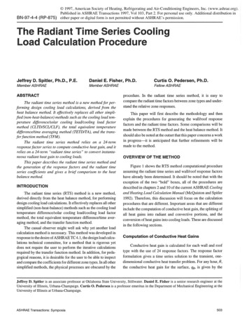
BN-97-4-4 (RP-875) 1997, American Society of Heating, Refrigerating and Air-Conditioning Engineers, Inc. (www.ashrae.org).Published in ASHRAE Transactions 1997, Vol 103, Part 2. For personal use only. Additional distribution ineither paper or digital form is not permitted without ASHRAE’s permission.The Radiant Time Series CoolingLoad Calculation ProcedureJeffrey D. Spitler, Ph.D., P.E.Member ASHRAEDaniel E. Fisher, Ph.D.Member ASHRAEABSTRACTThe radiant time series methodis a new methodfor performing design cooling load calculations, derived from theheat balancemethod.It effectively replaces all other simplified (non-heat-balance)methodssuch as the cool#zg load temperature difference solar cooling load cooling load factormethod (CLTD/SCL/CLF),the total equivalent temperaturedifference time averaging method (TETD/TA),and the transfer[unction method (TFM).The radiant time series method relies on a 24-termresponse factor series to computeconductiveheat gain, anditrelies on a 24-term "radiant time series" to convert instantaneous radiant heat gain to cooling loads.This paper describes the radiant time series methodandthe generation of the response factors and the radiant timeseries coefficients and gives a brief comparisonto the heatbalance method.INTRODUCTIONThe radiant time series (RTS) methodis a new method,derived directly fi"om the heat balance method,for performingdesigncoolingload calculations. It effectively replacesall othersimplified (non-heat-balance)methodssuch as the cooling loadtemperaturedifference/solar cooling load/cooling load factormethod,the total equivalent temperaturedifference/time averaging method,and the transfer function method.The casual observer might well ask whyyet another loadcalculation methodis necessary. This methodwas developedinresponseto the desire of ASHRAETC4.1, the design load calculations technical committee,for a methodthat is rigorous yetdoes not require the user to performthe iterative calculationsrequired by the transfer fimctionmethod.In addition, for pedagogicalreasons, it is desirablefor the user to be able to inspectand comparethe coefficients for different zonetypes. In all othersimplified methods,the physical processes are obscuredby theCurtis O. Pedersen, Ph.D.Fellow ASHRAEprocedure. In the radiant time series method, it is easy tocomparethe radiant time factors betweenzone types and understand the relative zoneresponses.This paper will first describe the methodologyand thenexplain the procedures for generating the wall/roof responsefactors and the radiant time factors. Somecomparisonswill bemadebetweenthe RTSmethodand the heat balance method. Itshouldalso be noted at the outset that this paper concernsa workin progress--it is anticipated that further refinementswill bemadeto the method.OVERVIEW OF THE METHODFigure 1 shows the RTSmethodcomputational procedureassumingthe radiant time series and wall/roof responsefactorshave already beendetermined. It should be noted that with theexception of the two "bold" boxes, all of the procedures aredescribed in chapters 2 and 10 of the current ASHRAECool#zgand Heating Load Calculation Manual(McQuistonand Spitler1992). Therefore, this discussion will focus on the calculationproceduresthat are different. Importantareas that are differentinclude the computationof conductiveheat gain, the splitting ofall heat gains into radiant and convective portions, and theconversionof heat gains into coolingloads. Theseare discussedin the followingsections.Computation of Conductive Heat GainsConductiveheat gain is calculated for each wall and rooftype with the use of 24 response factors. The response factorformulationgives a time series solution to the transient, onedimensionalconductiveheat transfer problem.For any hour, 0,the conductiveheat gain for the surface, qo, is given by theJeffrey D.Spitler is an associateprofessorat OklahomaState University,Stillwater. DanielE. Fisheris a senior researchengineerat theUniversityof Illinois, Urbana-Champaign.Curtis O. Pedersenis a professor emeritusin the Departmentof MechanicalEngineeringat theUniversityof Illinois at Urbana-Champaign.ASHRAETransactions:Symposia503
I CalculateI TransmittedSolari IC alculate tra smitted/I Isolar heat gain forL Ueachhoui",each window ICalculate solar intensities for /eachh ourf orI Calculate absorbedeach extedor/surfaceI ICalculateI /solar heat gainfo Abso/bed SNat each hour, each window’GainFacto,sI /Heat It mn r ut fntIf e chIDetermine infiltrationheat gai nISumallconvectivepoltions for eachhour Hourly ,.cooling ’loads cond cfio heat gain rfo;each] :,e,,o,[Calculate conductionheatgain for eachhour for eachwindow[ heat gainsga’ns IIhaatProcessall of theradiant heat gainsas t adianttm e series;either solar or non-solar,(conduction.lighting,people, equipmeat), Theresult ishourly coolingloadsdueto the r adiantheat gains,I hDeEat rgn iinnse equ i Pm eat FFigure 1Overviewof the radiant time seriessummationof the responsefactors multiplied by the temperaturedifference across the surface, as shownin Equation1:23qo A , Ypj(te, 0 -j5 - trc)j o(1)whereqote,O j6 hourly conductiveheat gain, Bttdh(W), for’ thesurface;surfacearea, ft 2 (m2);jth responsefactor; sol-air temperature, F ( C), j hoursago; andtrc presumedconstant roomair temperature, F ( C).Computationof Convective Heat GainsThe instantaneous cooling load is defined as the rate atwhichheat energyis convectedto the zoneair at a givenpoint intime. The computationof convectiveheat gains is co nplicatedby the radiant exchangebetweensurfaces, furniture, partitions,and other massin the zone. Radiantheat la’ansfer introduces tothe process a time dependencythat is not easily quantified. Heatbalance procedmes calculate the radiant exchange betweensurfacesbasedon their surface temperaturesand emissivities buttypically rely on estimated"radiative-convectivesplits" to deter504minethe contribution of internal heat sinks and sources to theradiant exchange.The radiant time series proceduresimplifiesthe heat balance procedureby splitting the conductiveheat gaininto radiative and convectiveportions (along with lights, occupants, and equipment)instead of simultaneouslysolving for theinstantaneous convective and radiative heat transfer fromeachsurface. Table1 contains provisional recommendationsfor splitting each of the heat gain components.Accordingto the radiant time series procedure, onceeachheat gain is split into radiative and convectiveportions, the heatgains can be convertedto coolingloads. Theradiative portion isabsorbedby the thermal massin the zone and then convectedintothe space. This process creates a time lag and dampeningeffect.The convective portion, on the other hand, is assumed toinstantly becomecooling load and, therefore, only needs to besummedto find its contribution to the hourly cooling load. Themethodfor convertingthe radiative portion to cooling loads isdiscussedin the next sections.Conversionof Radiative HeatGains Into Cooling LoadsTheradiant time series methodconverts the radiant portionof hourly heat gains to hourly cooling loads using radiant timefactors, the coefficients of the radiant timeseries. Likeresponsefactors, radiant time factors calculate the coolingload for theASHRAETransactions:Symposia
TABLE 1RecommendedRadiative-Convective Splits for Heat GainsRecommended RecommendedRadiativeConvectiveFractionFractionHeat Gain Recessedfluorescent-ventedto returnairRecessedfluorescent-ventedtosupplyand retumairIncandescentEquipment0.70,30 670.590 330.410.190.810.710.29Rudoyand Duran(1975)YorkandCappielo(1981), pp. 11.83-840.2-0.80.8-0.2Conductiveheat gain throughwails0.630.37Conductiveheat gain throughroofs0.840o16Transmittedsolar radiation1Absorbed(by fenestration)solar radiation r3q0-38 ""0.63 r23q0-238where coolingload (Q) for the current hour (0), heat gain for the current hour,qoqo-n6 heat gain n hours ago, andr o, rl, etc. radiant time factors.aoASHRAETC4.1 has ongoingresearch aimedat evaluatingthe radiative/convectivesplit for varioustypesof equipmenttypicallyfoundin offices, hospitals,etc. In the meantime,use highervaluesof radiationfractionsfor valuesof radiationfractionsfor fan-cooledequipment,e.g., computers.Thevalues presented here are based on standard ASHRAEsurfaceconductancesfor vertical wallswithhorizontalheatflowand e 0.9 andfor ceilings withheat flowdownwardande 0.9 Thecomputerprogramusedto generateradianttimefactors mayalso be usedto generatebetter estimatesofthe radiative/convectivesplit for wallsandroofK00437current houron the basis of current and past heat gains. Theradiant time series for a particular zonegives the time-dependentresponseof the zoneto a single steady periodic pulse of radiantenergy Theseries showsthe portion of the radiant pulse that isconvectedto the zoneair for each hour Thus, r 0 represents thefraction of the radiant pulse convectedto the zoneair in thecurrenthour, r1 in the last hour,andso on. Theradiant timeseriesthus generatedis used to convert the radiant portion of hourlyheat gains to hourly cooling loads accordingto Equation2.Qo roqo r]q0-8 r2q0-28Comments(2)Sameapproximationas for conductiveheat gain throughwalls the RTSMethod"discusses the procedurefor generating radianttime factors.Becausethe heat gains are all knownat this stage of the analysis, the coolingloads canall be calculatedexplicitly, eliminating the needfor an iterative solution.PROCEDURE FOR GENERATING WALLAND ROOF RESPONSE FACTORSIn order to use the methodology described above tocomputeconductive heat gain for walls and roofs, a set ofresponsefactors is neededfor each wall and roof that is usedinthe building of interest. Thereare a numberof waysto generatethe responsefactors; the methoddescribed here uses a conventional method(Hittle and Bishop1983)to calculate a set of t20responsefactors for a single pulse. (The large set of responsefactors was originally developedfor energy analysis where,using a weathertape, eachday is different fromthe one before.)Theresponsefactor set for a single pulse can be reducedto a setof 24 responsefactors that are appropriatefor a steady periodicinput. Thesewill be called periodic responsefactors.Radiant time factors are mostconveniently generated by aheat balance basedprocedure.A separate series of radiant timefactors is requiredfor eachuniquezoneandfor each uniqueradiant energydistribution function. Twodifferent series of radianttime factors are utilized--one for transmitted solar heat gainThe starting point for developing the periodic response(radiant energyassumedto be distributed to the floor only) andfactors for the conductioncomponentof heat gain is the tradione for all other types of heat gains (assumedto be uniformly tional response factor representation for the heat conductiondistributed on all internal surfaces). Thesection "Implementing througha wall:ASHRAETransactions:Symposia505
23q - , ZjTi, t-j8 Y YjTo, t j8j 0j owhereq nTi,t-j, To,t j (3)j 0heat flux at the inside surfaceof the wall at thecurrent hour,large numberdependenton the construction of thewall,responsefactors,inside surface temperaturejhour’s ago, andoutside surface temperaturej hours ago If the boundaryconditions are steady periodic within a 24hour period, it is usefirl to rearrange the summationsas follows:23q - ,23 YjTo, t-j ZjTi, t-j5j 0j 04747(4)- Z ZjTi, t-j8 Z YjTo, t j8j 2463j 2463- Z zjr,,, j8 Z rTo,, j .j 48j 48If the first term of the Z summationsis separatedfromthe rest,one obtains:q’ - ZoTi,t - . ZjTi, t-j j l23 . YjTo,t-jg-Z24Ti,t 24 o47(5)47-- 2 ZjTi,j 25t-jS Y, YjTo,j 246363j 49j 48t-j -ZasTi,t-48For a steady periodic forcing function, the temperaturesTi,t,Ti, t 24, Zi, t 48, etc., are all the same.Thecoefficientsof thesetemperatures can be combinedto give a new set of periodicresponsefactors (Zpj and YU):YPI Yo Y24 Y48 ’--(6)Y/’2 Y1 Y25 Y49 "’"(7)Similarly,and so on.Thus,for the special case of a steady periodicforcing function, the generally large numberof response factors can bereplacedby 24 periodicresponsefactors, andthe heat flux can beexpressedin terms of periodic responsefactors as50623q’ - X ZpjTi, t-j8 X YPjL, t-j8(8)j 0where the wall heat gain coefficients are designated to beeither inside coefficients (z) or’ cross-coefficients(y), depending on the temperatureby whichthey are multiplied.Furthermore,the inside temperatureis assumedconstant forcalculating design loads, and the sumof the Ypj coefficients isequalto the sumof the Zpj coefficients, so that Equation8 can berewritten as23q’ , Ypj(te, O-ja- trc)"j 0(9)By wayof example,consider a specific wall, in this case madeup of outside surface resistance, 4 in. (100 ram)face brick,in. (25 mm)insulation, 4 in. (100 mm)lightweight concreteblock, ¾ in. (20 mm)drywall, and inside surface resistance.This wall is type 10 wall, described in Table 18 of chapter 26of the 1993 ASHRAEHandbook -- Fundamentals (ASHRAE1993).A large set of response factors are computedusing themethoddescribed by Hittle and Bishop(1983) and are givenTable2. Usingthe proceduredescribed above, a set of 24 periodic responsefactor’s weredevelopedas shownin Figure 2.PROCEDURE FOR GENERATING RADIANTTIME FACTORS FROM HEAT BALANCEA procedure analogous to the periodic response factordevelopmentdemonstratesthat a series of 24 radiant time factorscompletely describes the zone response to a steady periodicinput. The24 radiant timefactors can be generatedby one of twoprocedures.First, the radiant timefactors can be generatedfroma zoneheat balancemodel.Sinceone of the goals of this projectwas to develop a simplified methodthat was directly based onthe heat balance method,it wasdeemeddesirable to generate theradiant time factors directly froma heat balance. Tothis end, aheat balance program, modeled on the BLASTprogram(BLASTSupport Office 1991) but limited to load calculationsf
Calculate solar intensities for / each h our f or each extedor / I Calculate absorbed surface I _ ICalculate I /solar heat gainfo /Heat Abso/bed SNat each hour, each window I Gain IFacto,s ’ I I t mn r ut fnt I cond cfio heat gain f e ch r fo;each] :,e,,o, [Calculate conduction heat gain for each hour for each window. Figure 1 [ heat gains. Ihaat ga’ns I. I hDeEat rgn .