Transcription
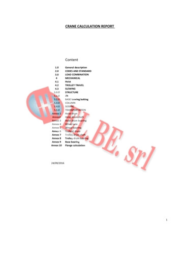
www.RitchiesOffshoreServicesCrane Calculation TemplateExample 1 Ground Pressure Known (Find Area of Pad Size)Outrigger Pont Loading (Based on 25tGround Bearing Pressure)Weight of crane weight of loadGround Bearing PressureWeight of Crane72tWeight of Counterweight 60t132tWeight of LoadHook Block / TackleFly Jib (If Fitted)11.4t0.7t0.5t132 x 0.75 (Point load) 11.4 0.7 0.5 111.6111.6 / 25 (GBP) 4.464m² 4.464 2.1128Pad Size 2.1Round Pad Size Up to 2.32.3 x 2.3 5.29m² (111.6 / 5.29 21.0t)Outrigger Point Load 21t
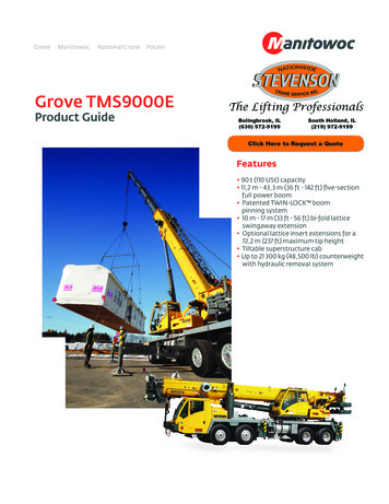
Example 2 Calculate from Pad SizeWeight of crane weight of loadArea of PadWeight of crane: 50 TonneWeight of load: 22 Tonne(Including Block / Tackle1.2 X 1.2 1.44m²Area of Outrigger Pad1.44 m²72 tonnes 1.44 X 75% X 10 (Converts into KiloNewtons) 37,500kN
Example 3 Ground Bearing Pressures Tables1. Crane WeightThe maximum weight of the crane to be used 50,000kgs (worst case scenario)2. LoadThe maximum load to be lifted 22,000kgs Load 1,500kgs3. Outrigger LoadPoint load (1 2) x 100% (50,000 23,500) x1 73,500kgs or 73.5t4. Ground TypeGround comes in granular and cohesive types.Bearing Values BS: 80045. Mat sizeMat size deducted from point load in 3 (in kNs) / (Soil type value 2)73500 x 9.81 721,035 kNs721.0kNs / 300KN/m2 2.40 m2 1.6m X 1.6m minimumA. Soil is compact ground (gravel 100mm in depth) covered in tar. Two outriggers will be placedhere. The other two will be placed on medium dense gravel [Dense gravel has a bearing valueof 600kNm2 medium dense gravel 200 – 600kNm2] Area has transport trailers carryingISO containers so a pessimistic ground bearing value of 300kNm has been selected.
Example 4 Outrigger Loading TemplateMat Area Calculation TemplateStage 1:Gross Load CalculationStage 2:Crane SelectionTemplateNet LoadLifting at height: Load x 1.2 (SF) t AccessoriesHook Block Stored Fly JibGross Load Crane Selected and Capacity:Counterweight / Ballast UsedBoom Length RequiredLength & Angle if Fly Jib UsedMaximum Radius From Load ChartmmMinimum Radius RequiredSWL at Radius UsedOutrigger SpreadStage 3:tttttttmdegSWLmtmmmmCrane UtilizationGross Load X 100 Divided by SWL @ the Radius Worked:WorkingsCrane Utilization%12t Per AxleStage 4:Crane Matt CalculationWeight of CraneCounterweight / Ballasttt X0.75% (Point Loading) Gross LoadTotal by Ground Bearing AllowanceArea of Mat Equals25 xtttkNsm²mTotal all up Weight Dived by the Area of Mat UsedPoint LoadStage 5:tBearing PressureActual Bearing Pressure Under Mat (Maximum Point Load)New Mat Size Area (Length x Breadth)Total all up Weight Dived by the Area of Mat Usedm²Or m Diameter if CircularResulting LoadingkNs
Converting Square to Round Pads1.6 X 1.6 2.56m2.56 3.14 0.815 0.815 .903 (Radius)X 2 1.8m (Dia)1.8m (Dia)Crane Utilisation:Load X 100 RadiusCrane Configuration – Radius: 12m – Boom length: 32.4m (Crane can lift 4.5 tons)Crane UtilisationLoad 4t x 100 4.5 88.8% Crane Utilization too high for hazardous area (Chemical Plant)You would need to Reduce Boom Length or Reduce Crane RadiusLoad 4t (@10m) x 100 5t 80.0% Crane Utilization Good
Wind Resistance Coefficient(See BS7121 Page 78)Wind Pressure on Load Resistance CoefficiencyCheck Wind Speed on Load Charts(Most Cranes have a Maximum Wind Speed of 9.8 M/P/S)Example OnlyMobile cranes are designed with a standard drag factor of 1.2 and a windarea/weight of 1.2 m²/tonne.This means that certain types of loads will producehigher side loads on the crane than it is designed totakeSail Area of Load2.5 X 8 20m² (Sail Area)2.5m15.5t8m
Wind Resistance Coefficient Maximum Permitted Wind Speed(For New Load) Maximum Wind Speed of Crane (Boom Configuration)1.2 Manufacture Test Standards(EN 13000 – 2010 / ISO 4306-2:2012)M Maximum Gross Weight Sail Area of Load Resistance Coefficient (1.4)(Example)1.2 x 15.5 18.6(Manufacture Test Standards) X (Load Weight)20 x 1.4 28 (wind load Area)18.6 28 0.66430.81504 x 12.8 10.4310.43 m/s (Maximum wind speed)2.5 X 8 20m²
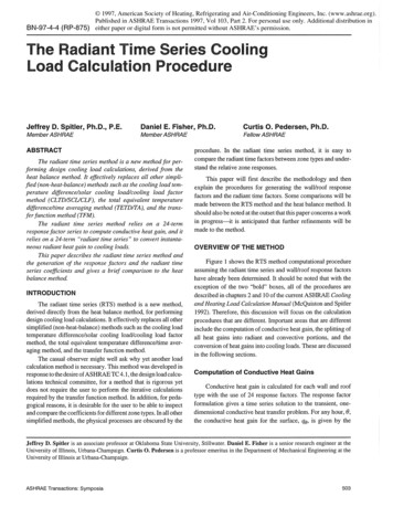
Slinging: 4 Leg2 L eg60 Angle60 Angle11.1m11.1m5m5m11.1mX11.1mXX12m Dia5mX10m5x5 10 x 10 25100125 125 11.1m slings to be used.Multiply 2.1 to Load weight to get SWL of sling12 x 75% 99 x 3.14 28.26m28.26 10 38.26mMultiply 1.4 to load weightfor SWL of slingMagic Sevens1x7 72 x 7 1.43 x 7 2.1(4 Legs sameas 3 legs)90 16 tonX Mode Factor to LoadTo calculate what SWL is needed for slingsMultiply 1.4 to load weight 16t1.4 x 16 22.4 tonne slings for lift
Crane Calculation Template Example 1 Ground Pressure Known (Find Area of Pad Size) Outrigger Pont Loading (Based on 25tGround Bearing Pressure) Weight of crane weight of load Ground Bearing Pressure Weight of Crane 72t Weight of Counterweight 60t 132t Weight of Load 11.4t Hook Block / Tackle 0.7t Fly Jib (If Fitted) 0.5t 132 x 0.75 (Point load) 11.4 0.7 0.5 111.6 111.6 / 25 (GBP) 4 .File Size: 2MBPage Count: 9