Transcription
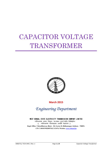
DISTRIBUTION TRANSFORMERSPECIFICATION #1212.0315kV Single Phase Submersible TransformerStainless Steel12/2/2011Page 1 of 8
1.SCOPEThis specification covers single-phase submersible transformers for use on a the District’s 12470GrdY/7200 Volt 60 Hertz,. underground distribution system and appropriate for 3 banking Thetransformers are intended for installation below ground in vaults and for operation on a primaryloop or radial system. The transformers shall be suitable for continuous submersion. Thetransformers will be connected phase-to-neutral in both single-phase or three-phase applications.The low voltage windings will be connected closed delta or closed Y.2.STANDARDSAll material and equipment furnished under these specifications shall conform to the latestapplicable approved standards of the IEEE, ANSI, and NEMA, except as otherwise specifiedherein.3.RATINGS3.1.All ratings shall be for 60 Hertz alternating current, oil immersed, self-cooledtransformers capable of continuous operation at rated kVA without exceeding either a55 C average temperature rise or a 70 C hot spot temperature rise.3.2.The electrical characteristics of the completely assembled high and low voltage terminalsshall be 7200/12470Y, and 120/240 (4 low-voltage bushings).3.3.The basic impulse level (BIL) shall be 95 kV.4.RADIAL FEEDTransformers will be suitable for radial feed.5.CONSTRUCTION5.1.Construction of the units shall be such that they can be lifted and lowered into place in asuitably designed and constructed enclosure having a minimum diameter of 36 inches. Toallow for cabling space and proper airflow for cooling, the transformers covered by thisstandard shall not have overall diameters in excess of 30 inches for sizes 100 kVA andsmaller, in excess of 33 inches for 167 kVA or 38 inches for 250kva and larger.5.2.The transformer tank, cover, and all external appurtenances shall be of corrosion-resistant304L stainless steel. This includes welds, plugs (may be brass), nameplates, etc.5.3.A protective (paint) coating of semi-gloss sky gray similar in color to ANSI Standard no.70 shall be applied that is at least 3 mils thick.5.4.Welds shall be smooth and shall not cut workers hand or gloves. The tank and cover shallbe capable of withstanding a full vacuum.5.5.Tank Cover5.5.1.5.5.2.The tank cover shall be welded to the tank. No handhole shall be installed in thecover.The threads between the oil fill plug and the boss on the tank shall be sealedwith a liquid pipe thread compound. Teflon tape is undesirable as it leavesshreds floating in the oil. Suggested products are Rectorseal, liquid Teflon, orsimilar sealants. If a fill plug is not provided, a 1/4-inch NPT boss with a brassplug shall be provided for the purpose of pressure testing.12/2/2011Page 2 of 8
5.6.Tank GroundThe tank grounding connection shall be per ANSI C57.12.20, Section 6.5.4 except:5.6.1. The connection shall consist of a stainless steel boss or pad and shall beequipped with a solder less tinned copper-alloy connector that willaccommodate #8 solid through #2 AWG stranded copper wire. The clampingeye bolt threads shall be 3/8-16NC.5.6.2. The tapped hole in the boss or pad and the stud of the connector shall be 1/2inch-13NC, Class 2 fit. The tapped hole shall be coated with an oxide-inhibitingcompound before installation of the connector.5.6.3. This connection shall be plainly labeled “G”.5.6.4. Extra tank ground bosses shall be protected with oxide-inhibiting compoundand a plastic flanged cup pressed into the threads (aluminum cups are notacceptable).5.7.Base bars of 401 Stainless Steel shall be provided on the transformer tank to protect thebottom of the tank while in transit and when installed in the underground enclosure.Minimum bar height is 1.00 inch.5.8.The lifting provisions shall be permanently attached and arranged on the tank to provide adistributive balanced lift in a vertical direction for the completely assembled transformer.They shall be designed to provide a safety factor of 5.6.TRANSFORMER TAPSNo transformer taps are required.7.CONNECTORS AND TERMINALS7.1.Primary Bushing7.1.1.7.1.2.7.1.3.7.1.4.7.2.Transformers shall come equipped with two high voltage bushing wells (H1 andH2), and corresponding load break inserts for dead front application. Thebushing wells shall be welded to the transformer cover, 200-amp rated,separable, and rated for primary switching per IEEE 386. Gasketed bushingwells are not acceptable. The bushing well shall have a cover or cap to preventthe entrance of moisture or dirt during shipping or storage. The cap shall besecured in a manner that prevents its loss during shipment or temporary storage.The bushings shall conform to IEEE C57.12.23.The load-break bushing inserts shall be Cooper Power Systems (Catalog No.2604797B01M) or Elastimold (Catalog No. 1601A4).One parking stand shall be welded in Segment 3 as shown in the latest IEEEC57.12.23.Secondary Terminals or Leads7.2.1.7.2.2.Four low-voltage cable leads (eight for 167 kVA, 250 kVA, and 333 kVA)extending 36 inches above the top of the cover shall be provided and arrangedfor vertical takeoff. The secondary neutral shall be floating and extended forexternal grounding.The cable insulation and sizes shall be in accordance with IEEE C57.12.23. The12/2/2011Page 3 of 8
7.2.3.7.3.8.9.ends of the cable leads shall be water sealed. The secondary bushing shall beplainly labeled X1, X3, X2, or X4, appropriately.The cable ends shall be sealed with a heat or cold shrink cap and can not beremoved without cutting the cap.Ground connections shall be suitably sized for the short-circuit rating of the transformeras defined in the latest IEEE C57.12.00FUSING8.1.Transformer H1 bushing leads shall be provided with Cooper Power Systems Bay-O-Net,dual sensing, load break, cover-mounted, externally removable links in series with underoil, internally mounted 15 kV partial range current limiting fuses (CLF). The partialrange fuse shall be manufactured by Cooper Power Systems (Type Multi-Coil ELSP).8.2.The partial range current limiting fuses shall be placed in series with the Bay-O-Net fuseholder and be mounted internally under oil. Partial range current limiting fuses shall havea nominal voltage rating of 15 kV.8.3.Fuses shall meet the Districts current fusing specifications which are shown below:Single PhaseKVABay-O-Net Fuse(Dual 30*indicates parallel fusingELSPRating(A)TRANSFORMER OILTransformers shall be insulated with new (unused) mineral oil. The oil shall meet therequirements of ANSI C57.12.00, Article 6.6.1 (1), ANSI C57.106 and ASTM 3487 Type II. Thetransformer nameplate shall indicate that the PCB content of said transformer is less than 1 PPMor at time of manufacture gas chromatographic analysis certified non-detectable PCB. The oilshall be inhibited mineral oil containing 0.2 % by weight DBPC.10. NOISETransformer sound levels shall not exceed the values specified in the latest revision of NEMAPublication TR 1-0.11.11. PAINT FINISH – NONE REQUIRED12. NAMEPLATES12.1. A stainless steel diagrammatic nameplate shall be affixed to the tank cover (or anynameplate extension bracket) using stainless steel fasteners. The nameplate shall state all12/2/2011Page 4 of 8
information per ANSI C57.12.00, nameplate A, except the nameplate shall include thefollowing:12.1.1. A manufacturer’s serial number barcode shall be etched into the nameplateusing a character size of 128A. The barcode shall be a maximum ½” high and2½” wide. The manufacturer’s identification characters shall not be included inthe barcode.12.1.2. The date (month/year) of manufacture. Serial numbers that include a date codewill not suffice.12.1.3. The statement “Contains less than one ppm PCB at time of manufacture.”Separate “NON PCB” stickers, labels, or extra nameplates will not suffice.12.1.4. The gallons of oil.12.1.5. The weight of the transformer for all sizes including 25 kVA.12.1.6. The manufacturer and catalog number for the primary fuses and fuse holder.12.1.7. Items a., c., d., and e., above, may be either on the nameplate or a separatestainless steel nameplate. Stenciling or other labels will not be acceptable.13. INSPECTIONThe purchaser shall at any reasonable time be permitted to have a representative visit theContractor’s factory for the purpose of witnessing manufacture of the transformers to ascertain ifthe material and process used in the manufacturing conform to the Specifications.14. TESTS14.1. Each transformer shall receive complete tests at the factory in accordance with latestANSI Standards. At the option of the District, transformers may be tested for acceptanceupon receipt.14.2. Test Tags. Each transformer shall have a durable, weatherproof tag firmly attached,reading:“This transformer has been tested at rated line voltage and has successfully passed allapplicabletests specified by ANSI and NEMA.” The tag shall show the transformer serial number, thedate,and name of the person who made the test. (State of Washington, Safety Statutes, Section19.29.010, Rule 5). NOTE: Slight variations in wording will be acceptable with priorapproval, and“computer-tested” units need not include a person’s name.15. EVALUATION AND AWARD15.1. For the purpose of evaluating bids in addition to the evaluation criteria set forth inSection B, Evaluation of Bids, consideration will be given to the following three items.Product QualityLoss Evaluation12/2/2011Page 5 of 8
Adherence to Specifications.15.2. Transformers will be evaluated on losses using the following criteria.15.2.1. Losses furnished for evaluation shall be guaranteed maximum losses for eachtransformer bid.15.2.2. No load losses (NLL) shall be in watts, at 20 C in accordance with ANSIC57.12.00.15.2.3. Full-load losses (FLL) shall be in watts, measured at rated nameplate load at85 C in accordance with ANSI C57.12.00.15.2.4. Losses will be evaluated at the following values:15.2.5. 4.07 per watt for no-load losses15.2.6. 1.79 per watt for full-load losses15.2.7. The manufacturer shall furnish with each transformer a certified test report ofthe no-load and full-load losses. The test report shall be submitted with theContractor’s invoice.15.3. Transformer evaluated prices will be determined as follows:Evaluated { 4.07 x NLL} { 1.79 x FLL]} {Base Price x (Transformer Evaluation Factor)}16. DATA TO BE SUBMITTED WITH BIDEach bidder shall submit with his proposal the data listed below. He shall submit a description ofany changes, additions or exceptions to the specification he proposes, together with reasons forthe departure. Product evaluation and conformance to specification will be determined on thebasis of information submitted. The drawings and data furnished must be in sufficient detail andclarity to enable making a complete and positive check with the technical provisions of thespecification.16.1. Outline drawings with overall dimensions.16.2. Details of the primary and secondary bushings. Manufacturers’ name and catalognumbers will suffice for primary bushings if no exceptions are requested. Secondarybushing details shall include (1) materials (cable or spade), (2) finish, such as plating, (3)dimensions (cable size length or spade size and thickness).16.3. Maximum core losses (no load) at 20 C and load losses (windings) at full load at 85 C.If other temperatures are used, provide an explanation and correction factor.16.4. That the transformer is a 55 C rise design.16.5. Impedance of windings at rated load expressed in percent of rated voltage.16.6. Information concerning details of construction, tank materials and tank finish. State gradeof stainless steel and total thickness of paint.16.7. Make and specification of oil. Uninhibited oil is unacceptable.16.8. Complete primary fuse data including fuses specified for each size of transformer.Include manufacturer and catalog number of fuse and holder.16.9. State all electrical tests given transformers at the factory and whether these tests apply to12/2/2011Page 6 of 8
all units or only sample units.16.10. Total weight of completely assembled transformer, including oil.16.11. A drawing of the transformer nameplate. Complete fuse data shall be shown on thenameplate: type, size, catalog number and manufacturer.17. WORKSMANSHIP, MATERIAL, AND FINISHAll workmanship and material used on the equipment shall be first class, the best of theirrespective kinds and shall be in full accordance with the most modern manufacturing practicesfor distribution transformers.18. PAYMENTThe contractors invoice must include itemized list of size (kVA) voltage and serial numbers ofunits sent, along with certified test reports before invoice will be paid. An order is not completeuntil certified test reports on each transformer shipped is in the District’s possession.19. DATA TO BE FURNISHED BY THE SUCCESSFUL BIDDERThe successful bidder shall supply:19.1. Three copies of outline dimensions of the transformer with accessories.19.2. Three copies of the transformer nameplate.19.3. Three copies of an instruction book covering installation, operation, and maintenance ofthe equipment furnished.19.4. One copy of certified test data for each transformer supplied. The test data shall containthe minimum following information:(1) core loss,(2) load loss,(3) exciting current at rated voltage,(4) insulation tests.20. DELIVERY20.1. The transformers shall be shipped F.O.B. destination to 1150 Hawley Street,Wenatchee, WA, 98801. The delivery will be accepted Monday through Fridaybetween the hours of 9:00 AM and 2:00 PM. No delivery of transformers will beaccepted on holidays. Please call Hawley Street Warehouse Foreman at (509) 6638121, Ext. 4730, 24 hours prior to deli
requirements of ANSI C57.12.00, Article 6.6.1 (1), ANSI C57.106 and ASTM 3487 Type II. The transformer nameplate shall indicate that the PCB content of said transformer is less than 1 PPM or at time of manufacture gas chromatographic analysis certified non-detectable PCB. The oil shall be inhibited mineral oil containing 0.2 % by weight DBPC. 10. NOISE Transformer sound levels shall not exceed .