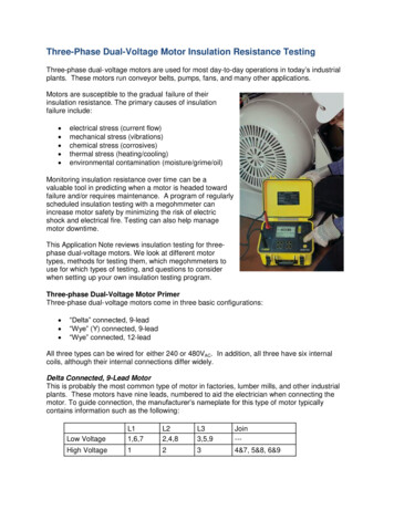
Transcription
VOLTAGE TRANSFORMER TESTING SWPThese competencies can be gained from, but not limited to any orall of the following:-1. PURPOSE AND SCOPEThe purpose of this Standard Work Practice (SWP) is to provideguidelines for testing methods for Capacitive and InductiveVoltage Transformers. These methods can be used for new andrefurbished transformers, maintenance testing or conditionassessment testing.Refer to the following locations for specific testing regimes: Qualifying as an Electrical Fitter Mechanic Qualifying as a Technical Service Person Practicing as an RPEQ Electrical Engineer Training in the safe use of relevant test equipment.Requirement for all live work: For new or refurbished construction’s, refer to theConstruction and Commissioning Tools. For standard maintenance testing, refer to the JAMIT jobcards and the Standard for Preventative MaintenanceProgram. For CVT Condition Assessment testing, refer toSP0508R02 CVT Diagnostic Testing Reference For all other Condition Assessment testing, consult theappropriate Commissioning and Maintenance orSubstation Maintenance engineer or officer for guidance.Non-standard testing requires appropriate RPEQapproval.Safety Observer (required for all “live work” as defined inthe ESO Code of Practice for Electrical Work)All resources are required to: Have appropriate Switching and Access authorisations forthe roles they are required to perform and have the abilityto assess and maintain relevant exclusion zones fromexposed live electrical apparatus. Hold current licences for any vehicles and equipment theymay be required to operate.Required TrainingStaff must be current in all Statutory Training relevant for the task.The requirements for Revenue Metering applications are notincluded in this SWP.All workers must have completed Field Induction or haverecognition of prior Ergon Energy Field Experience.Specialist testing for ferro-resonance or harmonic response is notincluded in this SWP.Contractors must have completed Ergon Energy's GenericContractor Worker Induction.2. STAFFING RESOURCES3. DOCUMENTATIONAdequate staffing resources with the competencies to safelycomplete the required tasks as per MN000301R165: 8 Level FieldTest Competency.CS000501F115. Daily/Task Risk Management PlanES000901R102. Health and Safety Risk Control GuidePage 1 of 19Ergon Energy Corporation Limited ABN 50 087 646 062Standard Work Practice SP0508 Ver 7
VOLTAGE TRANSFORMER TESTING SWPSP0508R01. Voltage Transformer Testing Job Safety Analysis4. KEY TOOLS AND EQUIPMENTSP0508C03. Voltage Transformer Testing CompetencyAssessmentSP0508C05. Commissioning Tool – Voltage TransformerTest Equipment within calibration date, tested and tagged:Insulation Resistance tester, Micro-ohmmeter, High Voltage testset, Digital Voltmeter, CVT test set, Ratiometer or PrimaryInjection Voltage source, Phase Angle meter and Ohmmeter,Omicron Votano and VB02.SP0508R02. CVT Diagnostic Testing ReferenceSafety Barriers and warning signs.CVT Test Equipment Specific DocumentHVIA Operating Equipment: PEDs, Live Line Tester, Class 0gloves. All equipment is to be inspected and confirmed in goodworking condition and within test date prior to use.SP0508C06. Construction Tool – Voltage TransformerSP0506. Substation Primary Plant and Secondary Systems FieldTesting SWPStandard PPE: Full-length high visibility protective cotton clothing,safety footwear and helmet.STNW1160. Standard for Maintenance Acceptance CriteriaMN000301R172. Doble DLA TestingAdditional PPE as required: Leather work gloves, class 00 gloves,hearing protection, safety eyewear. All PPE is to be inspectedand confirmed in good working condition and within test date(where applicable) prior to use.MPD 600 Test ProcedureP53. Operate the Network Enterprise ProcessAS 1243-1982 – Voltage transformers for measurement andprotection.Sun protection to be used when working outdoors.AS 60044.2-2007 – Instrument transformers – Inductive voltagetransformers.5. WORK PRACTICE STEPS5.1. Carry Out an Onsite Risk AssessmentAS 60044.3-2004 – Instrument transformers – Combinedtransformers.AS 60044.5-2004 – Instrument transformers – Capacitive voltagetransformers.Test Equipment Manuals.Voltage Transformer Manual / Manufacturer’s Drawings.Prior to performing this activity any hazards associated withprerequisite tasks at the worksite shall be identified and assessedwith appropriate control measures implemented and documentedin accordance with the Daily / Task Workplace RiskManagement Plan (CS000501F115) and using the Health andSafety Risk Control Guide reference document(ES000901R102).Page 2 of 19Ergon Energy Corporation Limited ABN 50 087 646 062Standard Work Practice SP0508 Ver 7
VOLTAGE TRANSFORMER TESTING SWPIf any risks cannot be managed or reduced to an acceptable level,do not proceed with the task and seek assistance from yourSupervisor.5.2. All Work to be done with Voltage Transformer De-EnergisedAll of the tests described in this SWP should be carried out withthe VT de-energised from the network and appropriate controlmeasures in place (eg barriers, matting) to prevent inadvertentcontact with adjacent live plant or breaching exclusion zones.P53 Operate the Network Process is applicable at all times forisolation and earthing where the VT forms part of the network. ATest Permit will be required for most testing to allow removal ofearths and injection of lethal voltages / currents.Where a VT is not part of the electrical network (e.g. greenfield orworkshop testing), sufficient safety measures must be applied toensure no person can contact plant during testing and all plant isearthed after HV testing prior to person’s contacting the plant. Induced voltages and currents from nearby energised /loaded plant. Stored energy in capacitive dividers.5.3. Assessment CriteriaUnless otherwise stated, refer to STNW1160 Standard forMaintenance Acceptance Criteria for applied test voltages andcurrents as well as acceptance test results for each test. Standardvalues may also be defined in the Construction andCommissioning Tools, JAMIT job cards or Operational Updates.For any conflicts, consult either the Commissioning andMaintenance or Substation Maintenance teams.Variations of test voltages, currents and acceptable test resultvalues can only be made with appropriate RPEQ approval.5.4. Record Identification Details Contact with high voltage at VT primary connections.Identification details are to be recorded in the Construction /Commissioning Tools, JAMIT job cards, etc. as required. Thesedetails are critical to ensure traceability of test results againstplant and correct asset details in corporate databases whichgenerate maintenance service tasks. High fault current at VT primary connections.Some typical details to confirm are: High fault current at VT secondary terminals, particularlyunfused wiring between secondary terminals andmarshalling box / secondary fuses. Manufacturer’s name, manufacturer’s type description andmanufacturer’s serial number. Plant/Asset number.Unearthed VT secondary winding. Description, ie. Magnetic, Capacitive etc.Open DLA test terminal. Rated transformation ratios (multiple secondary cores).A1 terminal of Primary winding not earthed correctly. Classification of all ratios.As described in Substation Primary Plant and Secondary SystemsField Testing SWP SP0506 particular safety risks applicable tobus assemblies including:Page 3 of 19Ergon Energy Corporation Limited ABN 50 087 646 062Standard Work Practice SP0508 Ver 7
VOLTAGE TRANSFORMER TESTING SWP Rated burden. Confirm structure earthing is in place and correct. Rated voltage level and insulation level. Rated frequency.Confirm if there are any external short from primary toearth (fuse wire is commonly used on CVT’s duringtransport and installation to prevent charging capacitorstack)5.5. Visual Inspection of Voltage Transformer ConditionCAUTION – A1 Terminal Earthing is criticalPrior to any electrical testing, complete a visual inspection on thevoltage transformer, its structure, earthing, etc. to confirm it is fitfor testing. Refer to the specific construction / commissioning toolor JAMIT job cards for specific checks.If the VT is a new installation, confirm that all construction itemsoutlined in the Construction Tool and manufacturer installationinstructions have been completed.Some basic inspections include: Ensure external surfaces are clean, dry and damage free. Look for external oil leaks, leaks into secondaryconnection boxes or EMU cases. Note that an oil leak insome CVTs can cause oil to transfer between thecapacitive stack and the EMU without an external leakbeing visible. Confirm oil/gas levels are acceptable. Confirm primary and secondary connections are correct,tight and correctly (new) / adequately (existing) labelled. Confirm any DLA tap covers are in place. Confirm primary and secondary earthing is in place andcorrect. For CVT’s, ensure the primary earth is eitherdirectly connected to earth or connected via power linecarrier communication equipment.Before beginning any testing, particularly primary voltageinjection, it is important to ensure that the A1 terminal on theprimary winding has been earthed. For CVTs, the A1 terminalmay be earthed directly or via the carrier line matching unit(where fitted). If the A1 terminal is disconnected for testing (eginsulation resistance measurement) then it must be reconnectedimmediately afterwards.If the A1 terminal is left disconnected when the VT/CVT isenergised, high voltage will be apparent on this terminal whichposes a serious safety risk to staff.Page 4 of 19Ergon Energy Corporation Limited ABN 50 087 646 062Standard Work Practice SP0508 Ver 7
VOLTAGE TRANSFORMER TESTING SWPAll SF6 gas handling is to be completed as per BS001404R140Management of SF6 Gas and its By-Products and STNW1117Standard for Handling of Sulphur Hexafluoride (SF6). Gassamples are required from: Gas in bottle Gas VT shipped with (if sufficient pressure) Gas in VT after filling Gas in VT 24hrs or greater after fillingWhile filling equipment is connected to plant, complete oil or gasalarms and lock out functions which are dependent on gaspressure or oil levels. Function check to the terminals of the VTrelays so further function checking can be completed from thislocation.Oil or gas levels are to be re-checked after all oil and gas testsand samples have been taken to confirm still within specifications.A1 terminal inadvertently left disconnectedOil and gas samples may be required to provide a benchmark forfuture testing. If required, take a sample as per the approvedprocess and forward to Powerlink for analysis.5.6. Oil / Gas Tests and SamplesTesting the insulating oil or gas medium is required to ensure theinsulation performs as intended by the manufacturer. If plant iselectrically tested or put into service with unknown insulationqualities, permanent damage to the plant can occur either duringtesting or while in service. If the plant is put into service withnon-satisfactory oil or gas, it could result in explosive failure.Below are typical situations were on site tests may be required toconfirm the integrity of the oil or gas prior to completing anyelectrical testing.All oil handling and filling is to be completed as perMN000301R173 Insulating Oil Equipment and Handling processand the equipment manual.Samples are only to be taken if the VT is designed to be sampled.Confirm with the equipment manual to confirm if possible.Page 5 of 19Ergon Energy Corporation Limited ABN 50 087 646 062Standard Work Practice SP0508 Ver 7
VOLTAGE TRANSFORMER TESTING SWPInstallationOilGasNew plant with no fillingrequired at siteNo (Note 1)YesNew plant with fillingrequired at siteYes (Note 1)YesRefurbished / intrusivelymaintained plantYesYes (Note 2)Existing plant with no refilling at siteNoNoExisting plant re-filled atsiteYes (Note 3)YesR1). PI helps distinguish between large charging and absorptioncurrents (non-destructive) with leakage currents (likelydestructive). As PI is a ratio, it is also not temperature dependentwhere as a single DCIR reading is. PI is typically only completedon HV insulation due to the larger charging and absorptioncurrents that can be expected. As such, most HV insulationrequires a 1 minute and 10 minute DCIR reading. A 5 minutereading can also be helpful in trending the DCIR increase overtime. PI is not relevant when DCIR values are high as the factorssuch as temperature and leakage currents are not greatlyaffecting readings.Note 1: Only sample hermetically sealed units that are designed to be sampled.Consult manufacturer manuals or Substation Maintenance for further informationif required.Note 2: Desiccant’s may also need to be replaced if intrusive maintenance hasbeen completed on SF6 filled equipment.Note 3: If only minor oil level top up, on site oil test not required. If refill requireddue to leak on plant that is supposed to be hermetically sealed, it is no longerhermetically sealed and should be treated as if it’s not sealed. ConsultSubstation Maintenance to have MST’s created.5.7. Measure Primary and Secondary Winding InsulationResistanceDC Insulation resistance tests (DCIR or IR) are one of the easiestand quickest ways to confirm phase to ground and winding towinding insulation integrity. It helps determine the health of theinsulation between components that are not supposed to beelectrically connected. DCIR does not test the inter-turninsulation.A product of DCIR tests is the polarisation index (PI). This is aratio of the 10 minute over 1 minute DCIR test results (PI R10 /DC insulation tests are to be carried out between all windings ofthe VT and earth. Winding terminals are to be shorted together toensure the whole winding is at the correct voltage. Appliedvoltages and allowable limits are specified in STNW1160Standard for Maintenance Acceptance Criteria (see note below ontest voltages based on neutral bushing voltage rating).Test arrangements include: HV to all Secondaries and Earth (g
VOLTAGE TRANSFORMER TESTING SWP Page 1 of 19 Standard Work Practice SP0508 Ver 7 Ergon Energy Corporation Limited ABN 50 087 646 062 1. all of the following:PURPOSE AND SCOPE The purpose of this Standard Work Practice (SWP) is to provide guidelines for testing methods for Capacitive and Inductive Voltage Transformers. These methods can be used for new and refurbished
